
User's Guide
Page 3
...PowerConnect 2808 9 PowerConnect 2816 9 PowerConnect 2824 10 PowerConnect 2848 10 Summary of PowerConnect Models 11 Features 11 General Features 11 MAC Address Supported Features 13 Layer 2 Features 13 VLAN Supported Features 14 Spanning Tree Protocol Features 15 Class of Service (CoS) Features 16 Ethernet Switch Management... Features 16 2 Hardware Description 17 Switch Port Configurations 17 PowerConnect 28xx Front and Back Panel Port Description 17 Physical Dimensions 21 LED Definitions 21 Power LED 22 Managed Mode LED 22 Fan LED (...
...PowerConnect 2808 9 PowerConnect 2816 9 PowerConnect 2824 10 PowerConnect 2848 10 Summary of PowerConnect Models 11 Features 11 General Features 11 MAC Address Supported Features 13 Layer 2 Features 13 VLAN Supported Features 14 Spanning Tree Protocol Features 15 Class of Service (CoS) Features 16 Ethernet Switch Management... Features 16 2 Hardware Description 17 Switch Port Configurations 17 PowerConnect 28xx Front and Back Panel Port Description 17 Physical Dimensions 21 LED Definitions 21 Power LED 22 Managed Mode LED 22 Fan LED (...
User's Guide
Page 4
... Configuration 44 Retrieving an IP Address From a DHCP Server 45 4 Contents Managed Mode 40 Initial Configuration - Power Connectors 26 Internal Power Supply Connector 26 3 Installing the PowerConnect Device 27 Installation Precautions 27 Site Requirements 28 Unpacking 28 Package Contents 28 Unpacking the Device 28 Mounting the Device 29 Overview 29 Device Rack ...
... Configuration 44 Retrieving an IP Address From a DHCP Server 45 4 Contents Managed Mode 40 Initial Configuration - Power Connectors 26 Internal Power Supply Connector 26 3 Installing the PowerConnect Device 27 Installation Precautions 27 Site Requirements 28 Unpacking 28 Package Contents 28 Unpacking the Device 28 Mounting the Device 29 Overview 29 Device Rack ...
User's Guide
Page 5
... Download 46 Erase FLASH File 46 Erasing the Device Configuration 47 Password Recovery 47 Software Download Through TFTP Server 47 Management Modes 49 Default Values 49 Transitioning Between Modes 50 Returning to Managed Mode 51 5 Using Dell OpenManage Switch Administrator 53 Understanding the Interface 53 Device Representation 54 Using the Switch Administrator Buttons 55 Information Buttons...
... Download 46 Erase FLASH File 46 Erasing the Device Configuration 47 Password Recovery 47 Software Download Through TFTP Server 47 Management Modes 49 Default Values 49 Transitioning Between Modes 50 Returning to Managed Mode 51 5 Using Dell OpenManage Switch Administrator 53 Understanding the Interface 53 Device Representation 54 Using the Switch Administrator Buttons 55 Information Buttons...

User's Guide
Page 11
...Dell PowerConnect 28xx Systems User Guide 11 Table 1-1. In this feature on all times, except when QoS (Quality of Service), Flow Control or Back Pressure is active on a port where the HOL blocking prevention mechanism is unavailable for additional incoming traffic. Provides switch management through the web interface. • Unmanaged Mode - This mode...8226; Secure Mode - For more information about the management modes, see "Management Modes" on the whole system. PowerConnect Models Model PowerConnect 2808 PowerConnect 2816 PowerConnect 2824 PowerConnect 2848 Copper Ports...
...Dell PowerConnect 28xx Systems User Guide 11 Table 1-1. In this feature on all times, except when QoS (Quality of Service), Flow Control or Back Pressure is active on a port where the HOL blocking prevention mechanism is unavailable for additional incoming traffic. Provides switch management through the web interface. • Unmanaged Mode - This mode...8226; Secure Mode - For more information about the management modes, see "Management Modes" on the whole system. PowerConnect Models Model PowerConnect 2808 PowerConnect 2816 PowerConnect 2824 PowerConnect 2848 Copper Ports...

User's Guide
Page 17
... 17 Hardware Description Switch Port Configurations PowerConnect 28xx Front and Back Panel Port Description The Dell™ PowerConnect™ 28xx switches use 10/100/1000BASE-T ports on or not. For more information about management modes and transitioning between management modes and to 8, top down and left side of the PowerConnect 28xx switches. PowerConnect 2808 Front Panel 2 On the front panel...
... 17 Hardware Description Switch Port Configurations PowerConnect 28xx Front and Back Panel Port Description The Dell™ PowerConnect™ 28xx switches use 10/100/1000BASE-T ports on or not. For more information about management modes and transitioning between management modes and to 8, top down and left side of the PowerConnect 28xx switches. PowerConnect 2808 Front Panel 2 On the front panel...

User's Guide
Page 18
...right side on or not. For more information about management modes and transitioning between management modes and to indicate the port status. Figure 2-4. PowerConnect 2808 Back Panel Figure 2-3. Figure 2-2. On each port ...Management Modes" on the front panel indicates whether the device is the Managed Mode LED which are LEDs to reset the device. PowerConnect 2816 Front Panel On the front panel there are 16 ports which indicates the Ethernet switch operational status and the management mode. The Power LED on page 49. PowerConnect 2816 Back Panel 18 Dell PowerConnect...
...right side on or not. For more information about management modes and transitioning between management modes and to indicate the port status. Figure 2-4. PowerConnect 2808 Back Panel Figure 2-3. Figure 2-2. On each port ...Management Modes" on the front panel indicates whether the device is the Managed Mode LED which are LEDs to reset the device. PowerConnect 2816 Front Panel On the front panel there are 16 ports which indicates the Ethernet switch operational status and the management mode. The Power LED on page 49. PowerConnect 2816 Back Panel 18 Dell PowerConnect...

User's Guide
Page 19
... a combo port can switch from the RJ-45 to the SFP (or vice versa) without resetting the device. PowerConnect 2824 Front Panel On the front panel there are 24 ports which indicates the Ethernet switch operational status and the management mode. NOTE: The system can be disabled. Dell PowerConnect 28xx Systems User Guide 19 Figure 2-5.
... a combo port can switch from the RJ-45 to the SFP (or vice versa) without resetting the device. PowerConnect 2824 Front Panel On the front panel there are 24 ports which indicates the Ethernet switch operational status and the management mode. NOTE: The system can be disabled. Dell PowerConnect 28xx Systems User Guide 19 Figure 2-5.

User's Guide
Page 20
... the device is the Managed Mode LED which offers high-speed 1000BASE-SX or 1000BASE-LX connection. There are numbered 1 to 48, top down and left to indicate the port status. NOTE: Only one time. NOTE: The system can be disabled. PowerConnect 2848 Front Panel On... transceiver, which indicates the Ethernet switch operational status and the management mode. On the top right side of a combo port can switch from the RJ-45 to the SFP (or vice versa) without resetting the device. A Mode push- 20 Dell PowerConnect 28xx Systems User Guide PowerConnect 2824 Back Panel Figure 2-7.
... the device is the Managed Mode LED which offers high-speed 1000BASE-SX or 1000BASE-LX connection. There are numbered 1 to 48, top down and left to indicate the port status. NOTE: Only one time. NOTE: The system can be disabled. PowerConnect 2848 Front Panel On... transceiver, which indicates the Ethernet switch operational status and the management mode. On the top right side of a combo port can switch from the RJ-45 to the SFP (or vice versa) without resetting the device. A Mode push- 20 Dell PowerConnect 28xx Systems User Guide PowerConnect 2824 Back Panel Figure 2-7.

User's Guide
Page 21
... Back Panel Physical Dimensions The PowerConnect 2808 switch has the following physical dimensions: • Height - 43.2 mm (1.7008 in.) • Width - 256 mm (10.079 in.) • Depth - 161.7 mm (6.366 in.) The PowerConnect 2816 and PowerConnect 2824 switches have the following physical dimensions: • ...32 in) • Depth - 255 mm (10.04 in .) The PowerConnect 2848 switch has the following figure illustrates the back panel of links, power supply, fan status, and Managed Mode status. Dell PowerConnect 28xx Systems User Guide 21 The back panel contains an AC Power Supply Interface...
... Back Panel Physical Dimensions The PowerConnect 2808 switch has the following physical dimensions: • Height - 43.2 mm (1.7008 in.) • Width - 256 mm (10.079 in.) • Depth - 161.7 mm (6.366 in.) The PowerConnect 2816 and PowerConnect 2824 switches have the following physical dimensions: • ...32 in) • Depth - 255 mm (10.04 in .) The PowerConnect 2848 switch has the following figure illustrates the back panel of links, power supply, fan status, and Managed Mode status. Dell PowerConnect 28xx Systems User Guide 21 The back panel contains an AC Power Supply Interface...

User's Guide
Page 22
... failed. Table 2-2. Fan LED (2824/2848 only) On the PowerConnect 2824 and PowerConnect 2848 front panel there is a Managed Mode LED monitoring the switch node as well as indicating diagnostic test results. The following figure illustrates the RJ-45 10/100/1000BASE-T LEDs. 22 Dell PowerConnect 28xx Systems User Guide Indicates the switch is a Power LED...
... failed. Table 2-2. Fan LED (2824/2848 only) On the PowerConnect 2824 and PowerConnect 2848 front panel there is a Managed Mode LED monitoring the switch node as well as indicating diagnostic test results. The following figure illustrates the RJ-45 10/100/1000BASE-T LEDs. 22 Dell PowerConnect 28xx Systems User Guide Indicates the switch is a Power LED...

User's Guide
Page 23
...The port is established. Switch Ventilation Fan The PowerConnect 2848 switch has three fans and the PowerConnect 2824 switch has one fan for at 10 or 100 Mbps. Dell PowerConnect 28xx Systems User Guide 23 The PowerConnect 2808 and PowerConnect 2816 devices have no internal fans. The port ... is occurring. No link is linked at 1000 Mbps. For more information about management modes and transitioning between them, see "Management Modes" on the front panel. Managed Mode Button The PowerConnect 28xx has a Mode push button on page 49. RJ-45 Copper-based 10/100/1000BASE-T LEDs ...
...The port is established. Switch Ventilation Fan The PowerConnect 2848 switch has three fans and the PowerConnect 2824 switch has one fan for at 10 or 100 Mbps. Dell PowerConnect 28xx Systems User Guide 23 The PowerConnect 2808 and PowerConnect 2816 devices have no internal fans. The port ... is occurring. No link is linked at 1000 Mbps. For more information about management modes and transitioning between them, see "Management Modes" on the front panel. Managed Mode Button The PowerConnect 28xx has a Mode push button on page 49. RJ-45 Copper-based 10/100/1000BASE-T LEDs ...
User's Guide
Page 39
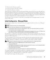
NOTE: It is to be downloaded from the Dell support website at http://support.dell.com. Starting and Configuring the Device After completing all external connections, connect a terminal to the device to configure the device and for....dell.com. For initial configuration, the standard device configuration is no need for this product. NOTE: The PowerConnect 2808 has an internal serial port. After completing all external connections, procede as an unmanaged switch, there is performed. 4 Dell PowerConnect 28xx Systems User Guide 39 The release notes can be used in a managed mode....
NOTE: It is to be downloaded from the Dell support website at http://support.dell.com. Starting and Configuring the Device After completing all external connections, connect a terminal to the device to configure the device and for....dell.com. For initial configuration, the standard device configuration is no need for this product. NOTE: The PowerConnect 2808 has an internal serial port. After completing all external connections, procede as an unmanaged switch, there is performed. 4 Dell PowerConnect 28xx Systems User Guide 39 The release notes can be used in a managed mode....
User's Guide
Page 40
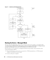
...Setup Press Esc Yes Suspend Bootup No Loading Program from flash to operate as a managed switch the boot procedure can be monitored on the connected terminal as a managed switch. The PowerConnect 2808/16/24/48 models include a built-in this section refers to the device when... between managed and unmanaged modes, press the Mode Button for less than seven seconds. Figure 4-1. Once the device is connected to a VT100 terminal device or VT100 terminal emulator via the RS-232 crossover cable. 2 Locate an AC power receptacle. 40 Dell PowerConnect 28xx Systems User Guide Managed Mode The ...
...Setup Press Esc Yes Suspend Bootup No Loading Program from flash to operate as a managed switch the boot procedure can be monitored on the connected terminal as a managed switch. The PowerConnect 2808/16/24/48 models include a built-in this section refers to the device when... between managed and unmanaged modes, press the Mode Button for less than seven seconds. Figure 4-1. Once the device is connected to a VT100 terminal device or VT100 terminal emulator via the RS-232 crossover cable. 2 Locate an AC power receptacle. 40 Dell PowerConnect 28xx Systems User Guide Managed Mode The ...
User's Guide
Page 41
..., the program flow stops. If POST passes successfully, a valid executable image is factory-set as possible. Managed Mode The information and procedures described in this section apply to the AC receptacle. 5 Activate the AC power receptacle. Dell PowerConnect 28xx Systems User Guide 41 NOTE: The switch is loaded into RAM. The system prompts you...
..., the program flow stops. If POST passes successfully, a valid executable image is factory-set as possible. Managed Mode The information and procedures described in this section apply to the AC receptacle. 5 Activate the AC power receptacle. Dell PowerConnect 28xx Systems User Guide 41 NOTE: The switch is loaded into RAM. The system prompts you...
User's Guide
Page 49
... the following table describes the Managed Mode LED indications. In this mode, you can return to Managed mode by pressing the Mode button on the device. From this mode, no web management interface is no web management interface, the CLI works in the CDB-default configuration is in debug mode only. admin • Permission - Off Dell PowerConnect 28xx Systems User Guide 49...
... the following table describes the Managed Mode LED indications. In this mode, you can return to Managed mode by pressing the Mode button on the device. From this mode, no web management interface is no web management interface, the CLI works in the CDB-default configuration is in debug mode only. admin • Permission - Off Dell PowerConnect 28xx Systems User Guide 49...
User's Guide
Page 50
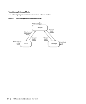
Transitioning Between Management Modes 50 Dell PowerConnect 28xx Systems User Guide Transitioning Between Modes The following diagram summarizes movement between modes: Figure 4-2.
Transitioning Between Management Modes 50 Dell PowerConnect 28xx Systems User Guide Transitioning Between Modes The following diagram summarizes movement between modes: Figure 4-2.
User's Guide
Page 51
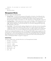
... Name - When restoring local configuration, this option uses the IP address, user name and password that were automatically saved when you exited Managed mode. Dell PowerConnect 28xx Systems User Guide 51 Returning to Managed Mode When returning to retrieve a saved configuration. Figure 4-3. When restoring local configuration, this option uses the system default IP address, user name...
... Name - When restoring local configuration, this option uses the IP address, user name and password that were automatically saved when you exited Managed mode. Dell PowerConnect 28xx Systems User Guide 51 Returning to Managed Mode When returning to retrieve a saved configuration. Figure 4-3. When restoring local configuration, this option uses the system default IP address, user name...
User's Guide
Page 56
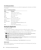
... a web browser. 2 Enter the device's IP address (as defined in the CLI) in Managed mode. NOTE: Passwords are automatically assigned one of configuring device information, and includes the following modes, based upon the access level assigned to you: 56 Dell PowerConnect 28xx Systems User Guide Access Levels When you login to a device, see "Static IP...
... a web browser. 2 Enter the device's IP address (as defined in the CLI) in Managed mode. NOTE: Passwords are automatically assigned one of configuring device information, and includes the following modes, based upon the access level assigned to you: 56 Dell PowerConnect 28xx Systems User Guide Access Levels When you login to a device, see "Static IP...
User's Guide
Page 63
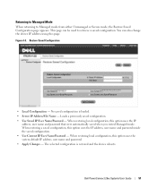
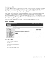
...the Secure management mode. Figure 6-5. Secure Mode Entering Secure Mode 1 Open the Secure Mode page. 2 Click Secure. The device enters Secure mode. Once enabled, it becomes inaccessible. To exit Secure Mode, press the Managed Mode button on page 80. For information about management modes, see "Managing Files" ... further configuration changes to enter the Managed Mode default configuration with your book title 63 Entering Secure Mode The Secure Mode page allows you to Secure Mode via the web interface. In Secure Mode the switch retains configuration through power ...
...the Secure management mode. Figure 6-5. Secure Mode Entering Secure Mode 1 Open the Secure Mode page. 2 Click Secure. The device enters Secure mode. Once enabled, it becomes inaccessible. To exit Secure Mode, press the Managed Mode button on page 80. For information about management modes, see "Managing Files" ... further configuration changes to enter the Managed Mode default configuration with your book title 63 Entering Secure Mode The Secure Mode page allows you to Secure Mode via the web interface. In Secure Mode the switch retains configuration through power ...
User's Guide
Page 157
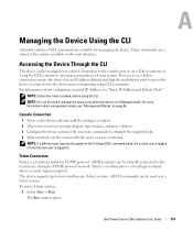
...number of the options available via the web interface. Using the CLI is required. A Dell PowerConnect 28xx Systems User Guide 157 These commands are a subset of CLI commands are available for managing the device. Telnet is an alternative to a local login terminal where a remote login ...is similar to entering commands on a Linux system. The device supports up to beginning using the CLI. For information about management modes, see "Static IP Address and Subnet Mask." Console Connection 1 Power on page 49. Telnet Connection Telnet is complete. 2 When the ...
...number of the options available via the web interface. Using the CLI is required. A Dell PowerConnect 28xx Systems User Guide 157 These commands are a subset of CLI commands are available for managing the device. Telnet is an alternative to a local login terminal where a remote login ...is similar to entering commands on a Linux system. The device supports up to beginning using the CLI. For information about management modes, see "Static IP Address and Subnet Mask." Console Connection 1 Power on page 49. Telnet Connection Telnet is complete. 2 When the ...


