Setup and Features Information Tech Sheet
Page 1
...Desktop Regulatory Model: D01S; Regulatory Type: D01S001 - Front and Back View 12 34 5 98 76 17 16 About Warnings WARNING: A WARNING indicates a potential for property damage, personal injury, or death. 10 11 15 1 drive activity light 2 Wi-Fi activity light 3 network activity light 1 4 network activity light 2 5 DVD drive bay 6 USB 2.0 connectors (2) 7 external power button connector 8 diagnostic lights (4) 9 power button, power light 10 power supply diagnostic button 11 power supply diagnostic light 12 12 cover-release latch 13 padlock ring 13 14 security cable slot...
...Desktop Regulatory Model: D01S; Regulatory Type: D01S001 - Front and Back View 12 34 5 98 76 17 16 About Warnings WARNING: A WARNING indicates a potential for property damage, personal injury, or death. 10 11 15 1 drive activity light 2 Wi-Fi activity light 3 network activity light 1 4 network activity light 2 5 DVD drive bay 6 USB 2.0 connectors (2) 7 external power button connector 8 diagnostic lights (4) 9 power button, power light 10 power supply diagnostic button 11 power supply diagnostic light 12 12 cover-release latch 13 padlock ring 13 14 security cable slot...
Setup and Features Information Tech Sheet
Page 2
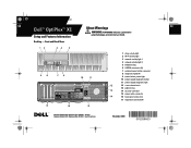
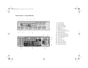
Front and Back View 12 3 4 5 9 8 7 6 17 16 10 11 12 13 14 15 1 drive activity light 2 Wi-Fi activity light 3 network activity light 1 4 network activity light 2 5 DVD drive bay 6 USB 2.0 connectors (2) 7 external power button connector 8 diagnostic lights (4) 9 power button, power light 10 power supply diagnostic button 11 power supply diagnostic light 12 cover-release latch 13 padlock ring 14 security cable slot 15 power cable connector 16 back panel connectors 17 expansion card slots (2) P609Nam0.fm Page 2 Thursday, October 15, 2009 5:17 PM Small Form Factor -
Front and Back View 12 3 4 5 9 8 7 6 17 16 10 11 12 13 14 15 1 drive activity light 2 Wi-Fi activity light 3 network activity light 1 4 network activity light 2 5 DVD drive bay 6 USB 2.0 connectors (2) 7 external power button connector 8 diagnostic lights (4) 9 power button, power light 10 power supply diagnostic button 11 power supply diagnostic light 12 cover-release latch 13 padlock ring 14 security cable slot 15 power cable connector 16 back panel connectors 17 expansion card slots (2) P609Nam0.fm Page 2 Thursday, October 15, 2009 5:17 PM Small Form Factor -
Setup and Features Information Tech Sheet
Page 3
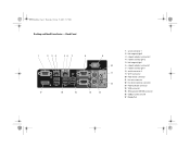
Back Panel 1 2 34 56 7 8 9 10 11 12 17 16 15 14 13 1 serial connector 1 2 link integrity light 2 3 network adapter connector 2 4 network activity light 2 5 link integrity light 1 6 network adapter connector 1 7 network activity light 1 8 serial connector 2 9 Wi-Fi connector 10 PS/2 mouse connector 11 line-out connector 12 line-in/microphone connector 13 PS/2 keyboard connector 14 VGA connector 15 24V powered USB 2.0 connector 16 USB 2.0 connectors (4) 17 DisplayPort P609Nam0.fm Page 3 Thursday, October 15, 2009 5:17 PM Desktop and Small Form Factor -
Back Panel 1 2 34 56 7 8 9 10 11 12 17 16 15 14 13 1 serial connector 1 2 link integrity light 2 3 network adapter connector 2 4 network activity light 2 5 link integrity light 1 6 network adapter connector 1 7 network activity light 1 8 serial connector 2 9 Wi-Fi connector 10 PS/2 mouse connector 11 line-out connector 12 line-in/microphone connector 13 PS/2 keyboard connector 14 VGA connector 15 24V powered USB 2.0 connector 16 USB 2.0 connectors (4) 17 DisplayPort P609Nam0.fm Page 3 Thursday, October 15, 2009 5:17 PM Desktop and Small Form Factor -
Setup and Features Information Tech Sheet
Page 4
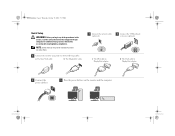
... adapter. 4 Connect the power cable(s). 5 Press the power buttons on the monitor and the computer. NOTE: Some devices may not be included if you begin any of the following cables: a The blue VGA cable. For additional best practices information, see www.dell.com/regulatory_compliance. d The VGA cable to DisplayPort adapter. b The DisplayPort cable. 1 Connect the network cable (optional). 2 Connect the USB keyboard or mouse (optional). P609Nam0.fm Page 4 Thursday, October 15, 2009 5:17 PM Quick Setup...
... adapter. 4 Connect the power cable(s). 5 Press the power buttons on the monitor and the computer. NOTE: Some devices may not be included if you begin any of the following cables: a The blue VGA cable. For additional best practices information, see www.dell.com/regulatory_compliance. d The VGA cable to DisplayPort adapter. b The DisplayPort cable. 1 Connect the network cable (optional). 2 Connect the USB keyboard or mouse (optional). P609Nam0.fm Page 4 Thursday, October 15, 2009 5:17 PM Quick Setup...
Setup and Features Information Tech Sheet
Page 5
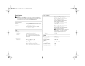
... specifications for your computer. P609Nam0.fm Page 5 Thursday, October 15, 2009 5:17 PM Specifications NOTE: The following specifications are only those required by law to ship with your computer, go to 3856 MB shared video memory (with 8 GB system memory) NOTE: Video memory will be dynamically assigned based on system board PCI-E x16 dual-channel graphics card with one DVI port and one DisplayPort connectors...
... specifications for your computer. P609Nam0.fm Page 5 Thursday, October 15, 2009 5:17 PM Specifications NOTE: The following specifications are only those required by law to ship with your computer, go to 3856 MB shared video memory (with 8 GB system memory) NOTE: Video memory will be dynamically assigned based on system board PCI-E x16 dual-channel graphics card with one DVI port and one DisplayPort connectors...
Setup and Features Information Tech Sheet
Page 6
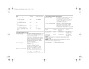
... computer is calculated by using the power supply wattage rating. P609Nam0.fm Page 6 Thursday, October 15, 2009 5:17 PM Drives Externally accessible: 5.25 inch drive bays Internally accessible: 3.5 inch SATA drive bay Available devices: 2.5 inch SATA hard drives 3.5 inch SATA hard drives 5.25 inch SATA DVD+/-RW drive Desktop one two two two one Small Form Factor one (slimline) one two one one (slimline) Control Lights and Diagnostic Lights Power button light Blue light - Solid blue light indicates power-on state; Blue...
... computer is calculated by using the power supply wattage rating. P609Nam0.fm Page 6 Thursday, October 15, 2009 5:17 PM Drives Externally accessible: 5.25 inch drive bays Internally accessible: 3.5 inch SATA drive bay Available devices: 2.5 inch SATA hard drives 3.5 inch SATA hard drives 5.25 inch SATA DVD+/-RW drive Desktop one two two two one Small Form Factor one (slimline) one two one one (slimline) Control Lights and Diagnostic Lights Power button light Blue light - Solid blue light indicates power-on state; Blue...
Dell™ OptiPlex™ XE - Installing Air-Ducts
Page 1
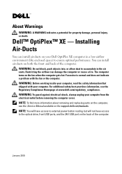
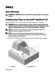
... allow dust to the optical drive, front USB ports, and the 24V USB port on your computer from the electrical outlet before removing the computer cover. The computer turns on the support.dell.com/manuals. WARNING: Before working inside your computer. You can install air-ducts on both the front and back of the computer. Fan noise is normal and does not indicate a problem with your computer...
... allow dust to the optical drive, front USB ports, and the 24V USB port on your computer from the electrical outlet before removing the computer cover. The computer turns on the support.dell.com/manuals. WARNING: Before working inside your computer. You can install air-ducts on both the front and back of the computer. Fan noise is normal and does not indicate a problem with your computer...
Installing Dust Filter on Your Dell™ OptiPlex™ XE
Page 1
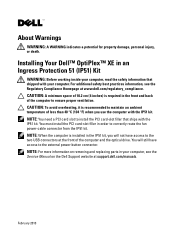
... filter slot Installing Dust Filter on a Small Form Factor computer with a 2.5 inch hard drive is 45 °C (113 °F) and with your computer. WARNING: Before working inside the slot located on a Desktop Form Factor computer is 42 °C (107.6 °F). 1 Slide the dust filter inside your computer. NOTE: The maximum operating temperature with the dust filter installed on Your Dell™ OptiPlex™ XE Dust...
... filter slot Installing Dust Filter on a Small Form Factor computer with a 2.5 inch hard drive is 45 °C (113 °F) and with your computer. WARNING: Before working inside the slot located on a Desktop Form Factor computer is 42 °C (107.6 °F). 1 Slide the dust filter inside your computer. NOTE: The maximum operating temperature with the dust filter installed on Your Dell™ OptiPlex™ XE Dust...
Installing Your Dell™ OptiPlex™ XE in an Ingress Protection 51 (IP51) Kit
Page 1
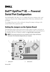
Installing Your Dell™ OptiPlex™ XE in order to correctly route the fan power-cable connector from the IP51 kit. You must install the PCI card-slot filler in an Ingress Protection 51 (IP51) Kit WARNING: Before working inside your computer, read the safety information that ships with the IP51 kit. NOTE: When the computer is installed in the IP51 kit, you use the computer with...
Installing Your Dell™ OptiPlex™ XE in order to correctly route the fan power-cable connector from the IP51 kit. You must install the PCI card-slot filler in an Ingress Protection 51 (IP51) Kit WARNING: Before working inside your computer, read the safety information that ships with the IP51 kit. NOTE: When the computer is installed in the IP51 kit, you use the computer with...
Dell™ OptiPlex™ XE - Powered Serial Port Configuration
Page 1
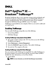
... access the jumpers on the system board, see the Setup and Features Information Tech Sheet that shipped with your computer, see the OptiPlex XE Service Manual available at support.dell.com/manuals. To configure the power to configure the power settings of the jumpers and the serial port on the system board or the expansion card. Setting the Jumpers on the System Board The illustration below shows the location of the serial connectors, based on your computer. 1 2 1 serial port...
... access the jumpers on the system board, see the Setup and Features Information Tech Sheet that shipped with your computer, see the OptiPlex XE Service Manual available at support.dell.com/manuals. To configure the power to configure the power settings of the jumpers and the serial port on the system board or the expansion card. Setting the Jumpers on the System Board The illustration below shows the location of the serial connectors, based on your computer. 1 2 1 serial port...
Dell™ OptiPlex™ XE - Broadcom® TruManage™
Page 1
...; System Setup (BIOS) • Dell Client Manager Enabling TruManage using DCM. The BIOS screen appears. 2 Select Maintenance→ System Management. 3 Select the DASH/ASF support checkbox. This enables TruManage. 4 Save and exit. You can remotely enable TruManage by using System Setup (BIOS) 1 Turn on the computer and press the key when you need to ensure that the Low Power Mode (LPM) is pre-installed on your Dell OptiPlex XE from a remote, centralized location. Enabling TruManage You can enable TruManage using either...
...; System Setup (BIOS) • Dell Client Manager Enabling TruManage using DCM. The BIOS screen appears. 2 Select Maintenance→ System Management. 3 Select the DASH/ASF support checkbox. This enables TruManage. 4 Save and exit. You can remotely enable TruManage by using System Setup (BIOS) 1 Turn on the computer and press the key when you need to ensure that the Low Power Mode (LPM) is pre-installed on your Dell OptiPlex XE from a remote, centralized location. Enabling TruManage You can enable TruManage using either...
Dell™ OptiPlex™ XE - Broadcom® TruManage™
Page 2
2 Use the DCM BIOS configuration feature to set ASF mode to DASH and ASF 2.0. 3 Use the DCM Power Control Task to the network ports is disabled when the computer is turned off, or hibernate mode when LPM is enabled. Environmental and Thermal Failures TruManage will alert you if the fan speed or the temperature is enabled by default on -LAN (WOL) will automatically disable LPM for the TruManage network port (network port 2) only. NOTE: Enabling TruManage will...
2 Use the DCM BIOS configuration feature to set ASF mode to DASH and ASF 2.0. 3 Use the DCM Power Control Task to the network ports is disabled when the computer is turned off, or hibernate mode when LPM is enabled. Environmental and Thermal Failures TruManage will alert you if the fan speed or the temperature is enabled by default on -LAN (WOL) will automatically disable LPM for the TruManage network port (network port 2) only. NOTE: Enabling TruManage will...
Dell™ OptiPlex™ XE - Watchdog Timer
Page 1
... from the Dell support website at support.dell.com/support/downloads. NOTE: If you see the Dell logo. NOTE: Ensure that Watchdog Timer is disabled before enabling it in the Microsoft® Windows® Task Manager. • define the actions to reboot continuously. NOTE: You must enable it first, can download and install Watchdog Timer from System Setup (BIOS). Watchdog Timer's hardware counter starts when you to: • monitor your...
... from the Dell support website at support.dell.com/support/downloads. NOTE: If you see the Dell logo. NOTE: Ensure that Watchdog Timer is disabled before enabling it in the Microsoft® Windows® Task Manager. • define the actions to reboot continuously. NOTE: You must enable it first, can download and install Watchdog Timer from System Setup (BIOS). Watchdog Timer's hardware counter starts when you to: • monitor your...
Dell™ OptiPlex™ XE - Watchdog Timer
Page 2
... "Changing the Refresh Interval" on page 11. Accessing Watchdog Timer To access Watchdog Timer: • Click the Dell OptiPlex XE Watchdog Timer icon on your computer during the following stages: • Turning on the computer • Loading the Operating System • After loading the Operating System In the Operating System interface, Watchdog Timer tracks the programs running in the Windows task manager. For...
... "Changing the Refresh Interval" on page 11. Accessing Watchdog Timer To access Watchdog Timer: • Click the Dell OptiPlex XE Watchdog Timer icon on your computer during the following stages: • Turning on the computer • Loading the Operating System • After loading the Operating System In the Operating System interface, Watchdog Timer tracks the programs running in the Windows task manager. For...
Dell™ OptiPlex™ XE - Watchdog Timer
Page 5
... or their products. All rights reserved. Setting the Auto run Feature To set the Auto run when system starts up check box to change without the written permission of Dell Inc. To enable the Program Status Monitor Log: 1 Click the Configuration tab on the Watchdog Timer's application interface. 2 Select Auto run feature: 1 Click the Configuration tab on the Watchdog Timer's application interface...
... or their products. All rights reserved. Setting the Auto run Feature To set the Auto run when system starts up check box to change without the written permission of Dell Inc. To enable the Program Status Monitor Log: 1 Click the Configuration tab on the Watchdog Timer's application interface. 2 Select Auto run feature: 1 Click the Configuration tab on the Watchdog Timer's application interface...
Technical Guidebook
Page 2
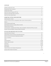
... System Manageability Modes, System Monitoring Options Memory Drives and Removable Storage System Board Connectors, Graphics/Video Controller External Ports/Connectors Communications-Integrated LAN, Wireless, Audio and Speakers, Keyboard and Mouse, Security Security, Service and Support, Software, System Accessories DETAILED ENGINEERING SPECIFICATIONS System Dimensions (Physical) System Board Connector Maximum Allowable Dimensions System Level Environmental and Operating Conditions Power, Compliance Audio Communications Graphics/Video Controller Hard Drives Optical Drive BIOS Defaults Chassis...
... System Manageability Modes, System Monitoring Options Memory Drives and Removable Storage System Board Connectors, Graphics/Video Controller External Ports/Connectors Communications-Integrated LAN, Wireless, Audio and Speakers, Keyboard and Mouse, Security Security, Service and Support, Software, System Accessories DETAILED ENGINEERING SPECIFICATIONS System Dimensions (Physical) System Board Connector Maximum Allowable Dimensions System Level Environmental and Operating Conditions Power, Compliance Audio Communications Graphics/Video Controller Hard Drives Optical Drive BIOS Defaults Chassis...
Technical Guidebook
Page 3
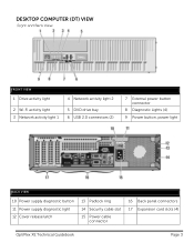
DESKTOP COMPUTER (DT) VIEW Front and Back View FRONT VIEW 1 Drive activity light 4 Network activity light 2 2 Wi-Fi activity light 3 Network activity light 1 5 DVD drive bay 6 USB 2.0 connectors (2) 7 External power button connector 8 Diagnostic Lights (4) 9 Power button, power light BACK VIEW 10 Power supply diagnostic button 11 Power supply diagnostic light 12 Cover release latch 13 Padlock ring 14 Security cable slot 15 Power cable connector 16 Back panel connectors 17 Expansion card slots (4) OptiPlex XE Technical Guidebook Page 3
DESKTOP COMPUTER (DT) VIEW Front and Back View FRONT VIEW 1 Drive activity light 4 Network activity light 2 2 Wi-Fi activity light 3 Network activity light 1 5 DVD drive bay 6 USB 2.0 connectors (2) 7 External power button connector 8 Diagnostic Lights (4) 9 Power button, power light BACK VIEW 10 Power supply diagnostic button 11 Power supply diagnostic light 12 Cover release latch 13 Padlock ring 14 Security cable slot 15 Power cable connector 16 Back panel connectors 17 Expansion card slots (4) OptiPlex XE Technical Guidebook Page 3
Technical Guidebook
Page 14
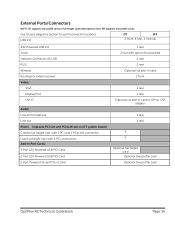
... 2 rear Optional via add-in card 1 front 1 rear 1 rear Optional via add-in card or DP-to-DVI adapter 1 rear 1 rear X X Optional full height card Optional low profile card Optional low profile card OptiPlex XE Technical Guidebook Page 14 SFF supports low profile cards. See chassis diagrams section for port/connector locations USB 2.0 DT SFF 2 front, 4 rear, 2 internal 24V Powered USB 2.0 Serial Network Connector (RJ-45) PS/2 Wireless Routing for external power Video: VGA Display Port DVI-D Audio: Line in/microphone Line out Risers: (replaces PCI slot and PCIex16 slot on DT system board...
... 2 rear Optional via add-in card 1 front 1 rear 1 rear Optional via add-in card or DP-to-DVI adapter 1 rear 1 rear X X Optional full height card Optional low profile card Optional low profile card OptiPlex XE Technical Guidebook Page 14 SFF supports low profile cards. See chassis diagrams section for port/connector locations USB 2.0 DT SFF 2 front, 4 rear, 2 internal 24V Powered USB 2.0 Serial Network Connector (RJ-45) PS/2 Wireless Routing for external power Video: VGA Display Port DVI-D Audio: Line in/microphone Line out Risers: (replaces PCI slot and PCIex16 slot on DT system board...
Technical Guidebook
Page 20
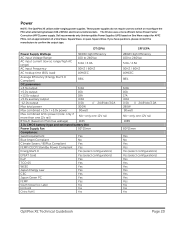
Power NOTE: The OptiPlex XE utilizes wide-ranging power supplies. If you have questions, please contact the manufacture to switch or reconfigure the PSU when alternating between 100-240VAC electrical currents/sockets. Dell recommends only Uninterruptible Power Supplies (UPS) based on PSU max wattage) 1163 3.3v CMOS battery (type and estimated battery life) Power Supply Fan 92*25mm Compliance: 1watt requirement Yes Blue Angel Compliant No Climate Savers...
Power NOTE: The OptiPlex XE utilizes wide-ranging power supplies. If you have questions, please contact the manufacture to switch or reconfigure the PSU when alternating between 100-240VAC electrical currents/sockets. Dell recommends only Uninterruptible Power Supplies (UPS) based on PSU max wattage) 1163 3.3v CMOS battery (type and estimated battery life) Power Supply Fan 92*25mm Compliance: 1watt requirement Yes Blue Angel Compliant No Climate Savers...
Technical Guidebook
Page 34
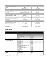
... -200 to 10600m BIOS Defaults N/A 8x DVD/ 24x CD 5V 800mA 5C to 50C 20% to 80% RH 29C -200 to 3048m -40C to 65C 5% to 95% RH 38C -200 to 10600m Drives System Configuration Video Diskette drive: SATA Operation; SMART Reporting: SATA-0: SATA-1: Integrated NIC: USB Controller: Serial Port #1: Serial Port #2: Front USB: Rear Dual USB (Under NIC1) and Powered USB: Rear Dual USB (Under NIC2): PCI Slots: WIFI NIC Slot: Audio: Primary Video: USB RAID On Disable Enable Enable Enable Enable Auto Auto Enable Enable Enable Enable Enable Enable Auto OptiPlex XE Technical Guidebook Page 34
... -200 to 10600m BIOS Defaults N/A 8x DVD/ 24x CD 5V 800mA 5C to 50C 20% to 80% RH 29C -200 to 3048m -40C to 65C 5% to 95% RH 38C -200 to 10600m Drives System Configuration Video Diskette drive: SATA Operation; SMART Reporting: SATA-0: SATA-1: Integrated NIC: USB Controller: Serial Port #1: Serial Port #2: Front USB: Rear Dual USB (Under NIC1) and Powered USB: Rear Dual USB (Under NIC2): PCI Slots: WIFI NIC Slot: Audio: Primary Video: USB RAID On Disable Enable Enable Enable Enable Auto Auto Enable Enable Enable Enable Enable Enable Auto OptiPlex XE Technical Guidebook Page 34


