
User Guide
Page 5
... Cage 75 Memory 76 Installing DIMMs 77 Removing DIMMs 79 Microprocessor 80 Front Panel Inserts 85 Removing Front Panel Inserts-Small Form-Factor and Small Desktop Computers 85 Removing Front Panel Inserts-Small Mini-Tower Computer . . 88 Replacing Front Panel Inserts 89 Internal Drives 89 IDE Drive Addressing 92 Connecting Drives...
... Cage 75 Memory 76 Installing DIMMs 77 Removing DIMMs 79 Microprocessor 80 Front Panel Inserts 85 Removing Front Panel Inserts-Small Form-Factor and Small Desktop Computers 85 Removing Front Panel Inserts-Small Mini-Tower Computer . . 88 Replacing Front Panel Inserts 89 Internal Drives 89 IDE Drive Addressing 92 Connecting Drives...
User Guide
Page 6
... Battery 132 4 Microsoft® Windows® XP Features Overview 136 Help and Support Center 136 New User Interface 137 Switching to Classic View 137 Clean Desktop Wizard 138 Taskbar Grouping 139 Notification Area Cleanup 139 Files and Settings Transfer Wizard 140 Application and Device Compatibility 141 Program Compatibility Wizard 141 System...
... Battery 132 4 Microsoft® Windows® XP Features Overview 136 Help and Support Center 136 New User Interface 137 Switching to Classic View 137 Clean Desktop Wizard 138 Taskbar Grouping 139 Notification Area Cleanup 139 Files and Settings Transfer Wizard 140 Application and Device Compatibility 141 Program Compatibility Wizard 141 System...

User Guide
Page 17
... the ResourceCD to reinstall drivers for your computer and devices User's Guides Depending on your operating system, double-click the User's Guides icon on your desktop or click the Start button and then select Help and Support to reinstall your computer. User's guides for the devices shipped with your computer. NOTE...
... the ResourceCD to reinstall drivers for your computer and devices User's Guides Depending on your operating system, double-click the User's Guides icon on your desktop or click the Start button and then select Help and Support to reinstall your computer. User's guides for the devices shipped with your computer. NOTE...
User Guide
Page 18
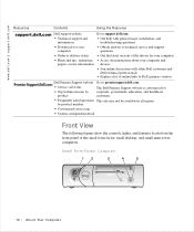
...professionals • Explore a list of online links to Dell's primary vendors Dell Premier Support website Go to technical service and support questions • Order or delivery status • Get the latest versions of the small form-factor, small desktop, and small mini-tower computers. Small Form-Factor ...Computer 12 3 4 5 16 Abo u t You r C o mp u t er by product The Dell Premier Support website is customized for your computer • Hints and...
...professionals • Explore a list of online links to Dell's primary vendors Dell Premier Support website Go to technical service and support questions • Order or delivery status • Get the latest versions of the small form-factor, small desktop, and small mini-tower computers. Small Form-Factor ...Computer 12 3 4 5 16 Abo u t You r C o mp u t er by product The Dell Premier Support website is customized for your computer • Hints and...

User Guide
Page 19
1 USB connectors (2) 2 Headphone connector 3 Hard drive access lights 4 Power button 5 Power light Small Desktop Computer 12 3 4 5 1 Front panel door 2 Power button 3 Power light 4 Hard drive access light 5 Floppy drive access light Abo u t Yo u r C o m p u te r 17
1 USB connectors (2) 2 Headphone connector 3 Hard drive access lights 4 Power button 5 Power light Small Desktop Computer 12 3 4 5 1 Front panel door 2 Power button 3 Power light 4 Hard drive access light 5 Floppy drive access light Abo u t Yo u r C o m p u te r 17

User Guide
Page 21
Small Desktop Computer 1 23 1 USB connectors (2) 2 Headphone connector 3 Breakaway hinges (2) Abo u t Yo u r C o m p u te r 19 This door is removable; if you remove it or accidentally knock it off its hinges, it snaps back in place. Front Panel Door Open the front panel door to access two Universal Serial Bus (USB) connectors and the headphone connector.
Small Desktop Computer 1 23 1 USB connectors (2) 2 Headphone connector 3 Breakaway hinges (2) Abo u t Yo u r C o m p u te r 19 This door is removable; if you remove it or accidentally knock it off its hinges, it snaps back in place. Front Panel Door Open the front panel door to access two Universal Serial Bus (USB) connectors and the headphone connector.
User Guide
Page 28
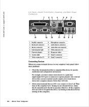
For example, you connect external devices to your computer is turned off. Fact or, Desktop, and Mini-Tower Computers 1 23 4 56 7 14 13 12 11 10 9 8 1 Parallel connector 2 Keyboard connector 3 Mouse connector 4 Link integrity light 5 Network adapter 6 Activity light 7 Video ... otherwise. (If the computer does not seem to load device drivers into computer memory before turning on the computer.) 26 Abo u t You r C o mp u t er www.dell.com | support.dell.com I /O) port or connector to operate properly.
For example, you connect external devices to your computer is turned off. Fact or, Desktop, and Mini-Tower Computers 1 23 4 56 7 14 13 12 11 10 9 8 1 Parallel connector 2 Keyboard connector 3 Mouse connector 4 Link integrity light 5 Network adapter 6 Activity light 7 Video ... otherwise. (If the computer does not seem to load device drivers into computer memory before turning on the computer.) 26 Abo u t You r C o mp u t er www.dell.com | support.dell.com I /O) port or connector to operate properly.

User Guide
Page 32
www.dell.com | support.dell.com Small Desktop Computer 14 1 13 2 12 11 3 4 10 9 8 7 5 6 1 Cover release buttons (2) 2 Hard drive 3 Internal speaker 4 Chassis intrusion switch 5 Expansion-card cage 6 Power supply 7 Expansion-card slots 8 AC power connector 9 Padlock ring 10 I/O ports and connectors 11 Heat sink assembly 12 System board 13 3.5-inch floppy drive 14 CD drive 30 Abo u t You r C o mp u t er
www.dell.com | support.dell.com Small Desktop Computer 14 1 13 2 12 11 3 4 10 9 8 7 5 6 1 Cover release buttons (2) 2 Hard drive 3 Internal speaker 4 Chassis intrusion switch 5 Expansion-card cage 6 Power supply 7 Expansion-card slots 8 AC power connector 9 Padlock ring 10 I/O ports and connectors 11 Heat sink assembly 12 System board 13 3.5-inch floppy drive 14 CD drive 30 Abo u t You r C o mp u t er

User Guide
Page 39
... stand with the screw hole in the cover. e Rotate the computer so that the drive bays are at the bottom. Abo u t Yo u r C o m p u te r 37 Small Desktop Computer Stand 2 To attach the computer stand, perform the following steps: a Place the computer on the side of the computer. d When the stand is at...
... stand with the screw hole in the cover. e Rotate the computer so that the drive bays are at the bottom. Abo u t Yo u r C o m p u te r 37 Small Desktop Computer Stand 2 To attach the computer stand, perform the following steps: a Place the computer on the side of the computer. d When the stand is at...
User Guide
Page 42
... management technology to the following industry standards: • Simple Network Management Protocol (SNMP) • Desktop Management Interface (DMI) • Common Information Model (CIM) The instrumentation available for configuring, managing, and monitoring computers and other devices on the Dell website. 40 Advanced Features Any changes that are available. IT Assistant supports instrumentation that...
... management technology to the following industry standards: • Simple Network Management Protocol (SNMP) • Desktop Management Interface (DMI) • Common Information Model (CIM) The instrumentation available for configuring, managing, and monitoring computers and other devices on the Dell website. 40 Advanced Features Any changes that are available. IT Assistant supports instrumentation that...

User Guide
Page 64
www.dell.com | support.dell.com NOTE: On the small form-factor and small desktop computers, remove the stand before you open the computer cover, see "Safety Instructions." Make sure that the computer is situated so that there is at ...
www.dell.com | support.dell.com NOTE: On the small form-factor and small desktop computers, remove the stand before you open the computer cover, see "Safety Instructions." Make sure that the computer is situated so that there is at ...

User Guide
Page 65
1 Security cable slot 2 Padlock ring 3 Release buttons (one on each side) Small Desktop Computer 1 3 2 1 Security cable slot 2 Padlock ring 3 Release buttons (one on each side) Instal ling Upgr ades 63
1 Security cable slot 2 Padlock ring 3 Release buttons (one on each side) Small Desktop Computer 1 3 2 1 Security cable slot 2 Padlock ring 3 Release buttons (one on each side) Instal ling Upgr ades 63

User Guide
Page 67
Expansion Card Types 1 2 1 Low-profile 32-bit PCI card 2 32-bit PCI card Instal ling Upgr ades 65 4 If you are using a padlock to four 32-bit, 33-MHz PCI cards. megahertz (MHz) Peripheral Component Interconnect (PCI) card. • In the small desktop computer, up to two 32-bit, 33-MHz PCI cards. • In the small mini-tower computer, up to secure your computer, reinstall the padlock. Expansion Cards Your computer provides expansion slots for the following cards: • In the small form-factor computer, one low-profile, 32-bit, 33-
Expansion Card Types 1 2 1 Low-profile 32-bit PCI card 2 32-bit PCI card Instal ling Upgr ades 65 4 If you are using a padlock to four 32-bit, 33-MHz PCI cards. megahertz (MHz) Peripheral Component Interconnect (PCI) card. • In the small desktop computer, up to two 32-bit, 33-MHz PCI cards. • In the small mini-tower computer, up to secure your computer, reinstall the padlock. Expansion Cards Your computer provides expansion slots for the following cards: • In the small form-factor computer, one low-profile, 32-bit, 33-
User Guide
Page 68
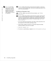
...seconds. 3 Open the computer cover. 4 If you are not supported. To locate this procedure, see "System Board Components." 1 If you have a small desktop computer, remove the expansion-card cage. 66 Instal ling Upgrades NOTICE: Before disconnecting a device from the computer or removing a component from its electrical outlet. IndustryStandard... disconnecting the computer from the system board, verify that the standby power light on the system board has turned off . www.dell.com | support.dell.com NOTE: To meet PC99 requirements, your Dell computer uses only PCI expansion slots.
...seconds. 3 Open the computer cover. 4 If you are not supported. To locate this procedure, see "System Board Components." 1 If you have a small desktop computer, remove the expansion-card cage. 66 Instal ling Upgrades NOTICE: Before disconnecting a device from the computer or removing a component from its electrical outlet. IndustryStandard... disconnecting the computer from the system board, verify that the standby power light on the system board has turned off . www.dell.com | support.dell.com NOTE: To meet PC99 requirements, your Dell computer uses only PCI expansion slots.

User Guide
Page 74
...outlets, and turn them on the screen at the next computer start-up: ALERT! www.dell.com | support.dell.com 1 Filler bracket 2 Alignment guide 3 Alignment bar 4 Retention arm 11 If you have a small desktop computer, replace the expansion-card cage. 12 Connect any cables that should be attached to... chassis intrusion detector by someone else, contact your network administrator for information on the I/O panel (see "I/O Panel-Small Form-Factor, Desktop, and Mini-Tower Computers"). 16 If you installed a sound card, enter system setup, perform the following steps: 72 Instal ling Upgrades
...outlets, and turn them on the screen at the next computer start-up: ALERT! www.dell.com | support.dell.com 1 Filler bracket 2 Alignment guide 3 Alignment bar 4 Retention arm 11 If you have a small desktop computer, replace the expansion-card cage. 12 Connect any cables that should be attached to... chassis intrusion detector by someone else, contact your network administrator for information on the I/O panel (see "I/O Panel-Small Form-Factor, Desktop, and Mini-Tower Computers"). 16 If you installed a sound card, enter system setup, perform the following steps: 72 Instal ling Upgrades

User Guide
Page 75
...Expansion Card CAUTION: Before you need a filler bracket, contact Dell. If you perform this light, see the illustration for ...adapter's connectors. b Connect the network cable to 20 seconds. 2 Open the computer cover. 3 In the small desktop computer, remove the expansion-card cage. 4 Press the lever on the expansion card retention arm and raise the retention...on the I/O panel (see "Safety Instructions." To locate this procedure, see "I/O Panel-Small Form-Factor, Desktop, and Mini-Tower Computers"). Instal ling Upgr ades 73 Do not connect the network cable to maintain Federal...
...Expansion Card CAUTION: Before you need a filler bracket, contact Dell. If you perform this light, see the illustration for ...adapter's connectors. b Connect the network cable to 20 seconds. 2 Open the computer cover. 3 In the small desktop computer, remove the expansion-card cage. 4 Press the lever on the expansion card retention arm and raise the retention...on the I/O panel (see "Safety Instructions." To locate this procedure, see "I/O Panel-Small Form-Factor, Desktop, and Mini-Tower Computers"). Instal ling Upgr ades 73 Do not connect the network cable to maintain Federal...
User Guide
Page 76
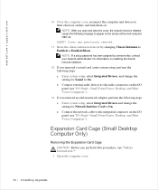
...and turn them on. Expansion Card Cage (Small Desktop Computer Only) Removing the Expansion-Card Cage CAUTION: Before you open and close the cover, the chassis intrusion detector causes the following message to On. www.dell.com | support.dell.com 10 Close the computer cover, reconnect the ...computer and devices to the integrated connector on the I/O panel (see "I /O Panel-Small Form-Factor, Desktop, and MiniTower Computers"). 13 If you removed an add-...
...and turn them on. Expansion Card Cage (Small Desktop Computer Only) Removing the Expansion-Card Cage CAUTION: Before you open and close the cover, the chassis intrusion detector causes the following message to On. www.dell.com | support.dell.com 10 Close the computer cover, reconnect the ...computer and devices to the integrated connector on the I/O panel (see "I /O Panel-Small Form-Factor, Desktop, and MiniTower Computers"). 13 If you removed an add-...

User Guide
Page 87
... to remove the front panel cover. Instal ling Upgr ades 85 Front Panel Inserts Removing Front Panel Inserts-Small Form-Factor and Small Desktop Computers 1 Open the computer cover. 2 Facing the front of the computer, use your computer and devices to verify that the Microprocessor... option correctly identifies the installed microprocessor. 13 Run the Dell Diagnostics to their electrical outlets, and turn them on. bend the pins if the chip is fully seated in "Microprocessor Heat Sink Removal...
... to remove the front panel cover. Instal ling Upgr ades 85 Front Panel Inserts Removing Front Panel Inserts-Small Form-Factor and Small Desktop Computers 1 Open the computer cover. 2 Facing the front of the computer, use your computer and devices to verify that the Microprocessor... option correctly identifies the installed microprocessor. 13 Run the Dell Diagnostics to their electrical outlets, and turn them on. bend the pins if the chip is fully seated in "Microprocessor Heat Sink Removal...

User Guide
Page 91
and one optional CD drive. • Small desktop: one floppy or optional Zip drive; one enhanced IDE hard drive; and two optional CD drives. Front Panel Insert Removal-Small Mini-Tower Computer Replacing ...
and one optional CD drive. • Small desktop: one floppy or optional Zip drive; one enhanced IDE hard drive; and two optional CD drives. Front Panel Insert Removal-Small Mini-Tower Computer Replacing ...

User Guide
Page 93
Small Desktop Computer 1 2 3 1 CD drive 2 Floppy drive 3 Hard drive Instal ling Upgr ades 91
Small Desktop Computer 1 2 3 1 CD drive 2 Floppy drive 3 Hard drive Instal ling Upgr ades 91


