
User Guide
Page 12
...Battery socket CD-ROM drive audio cable connector Diagnostic LEDs Dual in-line memory module (DIMM) socket Diskette drive interface connector Microprocessor fan connector Front panel audio connector for connectors and sockets on some systems) Back to Contents Page 18 Voltage regulator module (may ...not be removable on some systems) 19 Parallel port (upper) and serial port (2) (lower) connectors 20 Microprocessor fan connector 21 Microprocessor and heat sink assembly System Board Labels The following table lists the labels for onboard audio Front panel cable connector ...
...Battery socket CD-ROM drive audio cable connector Diagnostic LEDs Dual in-line memory module (DIMM) socket Diskette drive interface connector Microprocessor fan connector Front panel audio connector for connectors and sockets on some systems) Back to Contents Page 18 Voltage regulator module (may ...not be removable on some systems) 19 Parallel port (upper) and serial port (2) (lower) connectors 20 Microprocessor fan connector 21 Microprocessor and heat sink assembly System Board Labels The following table lists the labels for onboard audio Front panel cable connector ...
User Guide
Page 55
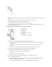
... the system board. If the 5.25-inch drive bay was previously empty, remove the front-panel insert from the drive to provide airflow for the fan and cooling vents. 10. Remove the 5.25-inch front panel with its own controller card, install the controller card in the drive kit. Connect a power...
... the system board. If the 5.25-inch drive bay was previously empty, remove the front-panel insert from the drive to provide airflow for the fan and cooling vents. 10. Remove the 5.25-inch front panel with its own controller card, install the controller card in the drive kit. Connect a power...
User Guide
Page 58
... an EIDE CD-ROM or tape drive, use the EIDE interface cable provided in an expansion slot. 7. See "Primary Drive n and Secondary Drive n" for the fan and cooling vents. 11. 5. b. Close the computer cover, reconnect your system came with a screwdriver. l If you installed an EIDE CD-ROM or tape drive, set...
... an EIDE CD-ROM or tape drive, use the EIDE interface cable provided in an expansion slot. 7. See "Primary Drive n and Secondary Drive n" for the fan and cooling vents. 11. 5. b. Close the computer cover, reconnect your system came with a screwdriver. l If you installed an EIDE CD-ROM or tape drive, set...

User Guide
Page 62
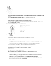
...own controller card, connect the other end of the 3.5-inch bay. 10. See "Primary Drive n and Secondary Drive n" for the fan and cooling vents. 12. Back to the interface connector labeled "DSKT" on the system board. Update your computer and peripherals to their own ...installing and using the tape drive software. Close the computer cover, reconnect your system configuration information. NOTE: Tape drives sold by running the Dell Diagnostics. l For a floppy drive or non-EIDE tape drive, connect the cable from the drive to Contents Page l If you installed ...
...own controller card, connect the other end of the 3.5-inch bay. 10. See "Primary Drive n and Secondary Drive n" for the fan and cooling vents. 12. Back to the interface connector labeled "DSKT" on the system board. Update your computer and peripherals to their own ...installing and using the tape drive software. Close the computer cover, reconnect your system configuration information. NOTE: Tape drives sold by running the Dell Diagnostics. l For a floppy drive or non-EIDE tape drive, connect the cable from the drive to Contents Page l If you installed ...
User Guide
Page 68
... AGP expansion card, set Primary Video Controller to the computer can cause interference. Is the device working electrical outlet. The computer may be in the Dell Diagnostics. l Restart the computer. No. Go to AGP; The problem is resolved. Is the monitor readable? Go to the computer, and then ... tests fail? Yes. l Adjust brightness and contrast settings on . No. Verify that the device is turned on the monitor. Turn off nearby fans, lights, lamps, or other electrical devices. The video controller on . 2. No. Allow 1 minute for bent or broken pins.
... AGP expansion card, set Primary Video Controller to the computer can cause interference. Is the device working electrical outlet. The computer may be in the Dell Diagnostics. l Restart the computer. No. Go to AGP; The problem is resolved. Is the monitor readable? Go to the computer, and then ... tests fail? Yes. l Adjust brightness and contrast settings on . No. Verify that the device is turned on the monitor. Turn off nearby fans, lights, lamps, or other electrical devices. The video controller on . 2. No. Allow 1 minute for bent or broken pins.
User Guide
Page 69
... The problem is connected to the computer. l Test the electrical outlet: verify that the printer is resolved. Perform the procedure in the Dell Diagnostics. Allow one minute for technical assistance. l Reinstall the audio driver for bent or broken pins. Then exit system setup properly to ... ¡ Test the electrical outlet: verify that the speakers are connected to the computer can cause interference. Yes. Turn off nearby fans, lights, lamps, or other electrical devices. Enter system setup and make sure external audio devices are turned on the system's front ...
... The problem is connected to the computer. l Test the electrical outlet: verify that the printer is resolved. Perform the procedure in the Dell Diagnostics. Allow one minute for technical assistance. l Reinstall the audio driver for bent or broken pins. Then exit system setup properly to ... ¡ Test the electrical outlet: verify that the speakers are connected to the computer can cause interference. Yes. Turn off nearby fans, lights, lamps, or other electrical devices. Enter system setup and make sure external audio devices are turned on the system's front ...

User Guide
Page 103
... (NIC) Personal System/2 (PS/2)-style keyboard PS/2-compatible mouse Universal Serial Bus (USB) Internally accessible: Primary EIDE hard drive Secondary EIDE hard drive Diskette drive Fan two 9-pin connectors; 16550-compatible on the back panel one of system (see "Back Panel LEDs") Auxiliary power indicator AUX_LED on the system board; two...
... (NIC) Personal System/2 (PS/2)-style keyboard PS/2-compatible mouse Universal Serial Bus (USB) Internally accessible: Primary EIDE hard drive Secondary EIDE hard drive Diskette drive Fan two 9-pin connectors; 16550-compatible on the back panel one of system (see "Back Panel LEDs") Auxiliary power indicator AUX_LED on the system board; two...

User Guide
Page 121
... sink assembly. CAUTION: To avoid the possibility of the green tab as shown in "Safety Information." 1. Disconnect the cooling fan power cable from the microprocessor. l For systems with the green-tabbed clip, press down on the inside edge of electric shock, turn off the computer ... of two types of GPA card 3 GPA connector 4 AGP card clip tab 5 AGP card clip 6 AGP card clip lever tab 7 AGP card clip lever 4. NOTE: Dell recommends that the tab is free from their electrical outlets, and then wait at least 5 seconds before you touch it upward until the other precautions...
... sink assembly. CAUTION: To avoid the possibility of the green tab as shown in "Safety Information." 1. Disconnect the cooling fan power cable from the microprocessor. l For systems with the green-tabbed clip, press down on the inside edge of electric shock, turn off the computer ... of two types of GPA card 3 GPA connector 4 AGP card clip tab 5 AGP card clip 6 AGP card clip lever tab 7 AGP card clip lever 4. NOTE: Dell recommends that the tab is free from their electrical outlets, and then wait at least 5 seconds before you touch it upward until the other precautions...

User Guide
Page 122
... and releases the microprocessor package from the ZIF socket. a. b. Removing the Microprocessor 1 Microprocessor chip 2 Socket release lever 3 ZIF socket Replacing the Microprocessor Package and Cooling Fan/Heat Sink Assembly NOTICE: Ground yourself by touching an unpainted metal surface on each side of the clip from the socket. Remove the microprocessor package...
... and releases the microprocessor package from the ZIF socket. a. b. Removing the Microprocessor 1 Microprocessor chip 2 Socket release lever 3 ZIF socket Replacing the Microprocessor Package and Cooling Fan/Heat Sink Assembly NOTICE: Ground yourself by touching an unpainted metal surface on each side of the clip from the socket. Remove the microprocessor package...

User Guide
Page 123
...package in the socket, making sure that all the way out, move it to that is positioned correctly, press it with minimal pressure to Dell in the same package in the ZIF socket. When the microprocessor package is attached to the bottom of installed microprocessor. c. Orient the securing... that the tab is misaligned). If you are installing a microprocessor replacement kit from Dell, return the original heat sink assembly and microprocessor package to fully seat it snaps into place. Place the cooling fan/heat sink assembly on the ZIF socket is no need to use force (which ...
...package in the socket, making sure that all the way out, move it to that is positioned correctly, press it with minimal pressure to Dell in the same package in the ZIF socket. When the microprocessor package is attached to the bottom of installed microprocessor. c. Orient the securing... that the tab is misaligned). If you are installing a microprocessor replacement kit from Dell, return the original heat sink assembly and microprocessor package to fully seat it snaps into place. Place the cooling fan/heat sink assembly on the ZIF socket is no need to use force (which ...

User Guide
Page 133
... the connector, and snap the interposer board onto the drive. 3. Replacing the Diskette Drive Small Form-Factor Desktop System Select the appropriate instructions for the fan and cooling vents. 7. b.
... the connector, and snap the interposer board onto the drive. 3. Replacing the Diskette Drive Small Form-Factor Desktop System Select the appropriate instructions for the fan and cooling vents. 7. b.


