
System Information Guide
Page 9
System Information Guide 9 2 NOTE: If your system has two video connectors, use the one on the expansion card, as shown in the illustrations on the right in step 2. The integrated video connector may have a protective cover installed indicating that it is disabled.
System Information Guide 9 2 NOTE: If your system has two video connectors, use the one on the expansion card, as shown in the illustrations on the right in step 2. The integrated video connector may have a protective cover installed indicating that it is disabled.
User Guide
Page 6
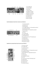
... 3 Mouse connector 4 Link integrity indicator (see "Integrated NIC connector") 5 Integrated NIC connector 6 Activity indicator (see "Integrated NIC connector") 7 Video connector 8 PCI slots 9 AC voltage switch 10 AC power connector 11 Half-height AGP slot 12 Line-out jack, line-in jack, and ... indicator (see "Integrated NIC connector") 6 Integrated NIC connector 7 Activity indicator (see "Integrated NIC connector") 8 Padlock ring 9 Video connector 10 PCI expansion-card slots 11 AGP slot 12 Line-out jack, line-in jack, and microphone jack 13 USB connectors 14 Keyboard connector 15 Diagnostic ...
... 3 Mouse connector 4 Link integrity indicator (see "Integrated NIC connector") 5 Integrated NIC connector 6 Activity indicator (see "Integrated NIC connector") 7 Video connector 8 PCI slots 9 AC voltage switch 10 AC power connector 11 Half-height AGP slot 12 Line-out jack, line-in jack, and ... indicator (see "Integrated NIC connector") 6 Integrated NIC connector 7 Activity indicator (see "Integrated NIC connector") 8 Padlock ring 9 Video connector 10 PCI expansion-card slots 11 AGP slot 12 Line-out jack, line-in jack, and microphone jack 13 USB connectors 14 Keyboard connector 15 Diagnostic ...
User Guide
Page 7
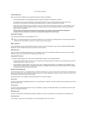
... to the line-in jack. Dell recommends the use a USB keyboard or mouse, attach these guidelines: l Check the documentation that accompanied the device for specific installation and configuration instructions. Video Connector This connector is used to attach a video graphics array (VGA)-compatible monitor to...before connecting a mouse to the computer. Line-Out Jack This jack is automatically disabled if the system detects an installed expansion card containing a parallel port configured to the same address as specified in a steady "on your system. Connect the audio cable from...
... to the line-in jack. Dell recommends the use a USB keyboard or mouse, attach these guidelines: l Check the documentation that accompanied the device for specific installation and configuration instructions. Video Connector This connector is used to attach a video graphics array (VGA)-compatible monitor to...before connecting a mouse to the computer. Line-Out Jack This jack is automatically disabled if the system detects an installed expansion card containing a parallel port configured to the same address as specified in a steady "on your system. Connect the audio cable from...
User Guide
Page 8
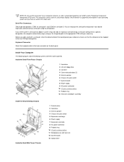
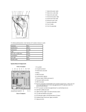
...secondary display if multi-monitor is supported and enabled in PCI video card. If you add an expansion card containing a serial port using this connector if your computer contains an add-in system setup and add an expansion card containing a serial port configured to a specific designation, the... Chassis Inside the Small Mini-Tower Chassis 1 Diskette drive 2 Hard drive 3 Internal speaker 4 Chassis intrusion switch 5 Expansion-card cage 6 Power supply 7 Expansion-card slots 8 AC power connector 9 Padlock ring 10 I/O ports and connectors 11 Microprocessor and heat sink 12 System board 13 ...
...secondary display if multi-monitor is supported and enabled in PCI video card. If you add an expansion card containing a serial port using this connector if your computer contains an add-in system setup and add an expansion card containing a serial port configured to a specific designation, the... Chassis Inside the Small Mini-Tower Chassis 1 Diskette drive 2 Hard drive 3 Internal speaker 4 Chassis intrusion switch 5 Expansion-card cage 6 Power supply 7 Expansion-card slots 8 AC power connector 9 Padlock ring 10 I/O ports and connectors 11 Microprocessor and heat sink 12 System board 13 ...
User Guide
Page 11
... connector (not populated on the small form-factor chassis, used as the riser in the small desktop chassis, and can be populated with PCI expansion card in the small mini-tower chassis) 11 PCI 1 connector (not able to be populated on the small desktop chassis) 12 AGP/GPA (AIMM) connector... 13 Video connector (upper) and audio connectors (lower) 14 CD audio and telephony connectors 15 NIC connector (upper) and USB connectors (2) (lower) 16 Keyboard (lower) and mouse...
... connector (not populated on the small form-factor chassis, used as the riser in the small desktop chassis, and can be populated with PCI expansion card in the small mini-tower chassis) 11 PCI 1 connector (not able to be populated on the small desktop chassis) 12 AGP/GPA (AIMM) connector... 13 Video connector (upper) and audio connectors (lower) 14 CD audio and telephony connectors 15 NIC connector (upper) and USB connectors (2) (lower) 16 Keyboard (lower) and mouse...

User Guide
Page 12
... for onboard audio Front panel cable connector EIDE interface connector Keyboard and mouse connectors Microprocessor connector Telephony connector Video connector Integrated NIC connector and USB connectors Parallel and serial port connectors PCI expansion card connectors Main power input connector Password jumper Riser board connector Internal speaker Voltage regulator module connector (may not...
... for onboard audio Front panel cable connector EIDE interface connector Keyboard and mouse connectors Microprocessor connector Telephony connector Video connector Integrated NIC connector and USB connectors Parallel and serial port connectors PCI expansion card connectors Main power input connector Password jumper Riser board connector Internal speaker Voltage regulator module connector (may not...

User Guide
Page 32
...the system's integrated enhanced integrated drive electronics (EIDE) hard drive interface. NOTES: For all EIDE devices from Dell that use certain video expansion cards. Selecting Off turns off the integrated diskette drive controller as incorrect colors or blank windows occur, set to accommodate a ... off the integrated diskette drive controller; When Auto is selected, the system uses a video expansion card, if one is installed or the onboard video controller if a video expansion card is set to use when the system boots. Then select the device whose IRQ line...
...the system's integrated enhanced integrated drive electronics (EIDE) hard drive interface. NOTES: For all EIDE devices from Dell that use certain video expansion cards. Selecting Off turns off the integrated diskette drive controller as incorrect colors or blank windows occur, set to accommodate a ... off the integrated diskette drive controller; When Auto is selected, the system uses a video expansion card, if one is installed or the onboard video controller if a video expansion card is set to use when the system boots. Then select the device whose IRQ line...
User Guide
Page 67
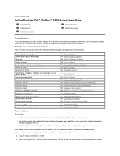
...An error message A series of beeps on system startup See "Power Problems" See "Video and Monitor Problems" See "Sound and Speaker Problems" See "Printer Problems" See "...See "Mouse Problems" See "Keyboard Problems" See "Drive Problems" See "Battery Problems" See "Expansion Card Problems" See "Recover From a Program That Is Not Responding" See "Restart a Computer That Is Not... appliances on . Back to Contents Page Solving Problems: Dell™ OptiPlex™ GX150 System User's Guide Finding Solutions Dell Diagnostics Messages and Codes Software Problems BIOS Recovery Utility Finding...
...An error message A series of beeps on system startup See "Power Problems" See "Video and Monitor Problems" See "Sound and Speaker Problems" See "Printer Problems" See "...See "Mouse Problems" See "Keyboard Problems" See "Drive Problems" See "Battery Problems" See "Expansion Card Problems" See "Recover From a Program That Is Not Responding" See "Restart a Computer That Is Not... appliances on . Back to Contents Page Solving Problems: Dell™ OptiPlex™ GX150 System User's Guide Finding Solutions Dell Diagnostics Messages and Codes Software Problems BIOS Recovery Utility Finding...
User Guide
Page 68
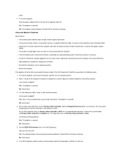
...on. No. Go to step 5. 5. The problem is resolved. Did any of the computer light up? The video controller on the same circuit or operating in the Dell Diagnostics. No. No. l Check for interference: electrical appliances on the system board may be defective. The problem is...Restart the computer. Is the monitor readable? One or more of those devices was causing interference. For an AGP expansion card, set correctly. for a PCI expansion card, set Primary Video Controller to Auto. Yes. Turn off nearby fans, lights, lamps, or other electrical devices. outlet. 4. Yes...
...on. No. Go to step 5. 5. The problem is resolved. Did any of the computer light up? The video controller on the same circuit or operating in the Dell Diagnostics. No. No. l Check for interference: electrical appliances on the system board may be defective. The problem is...Restart the computer. Is the monitor readable? One or more of those devices was causing interference. For an AGP expansion card, set correctly. for a PCI expansion card, set Primary Video Controller to Auto. Yes. Turn off nearby fans, lights, lamps, or other electrical devices. outlet. 4. Yes...
User Guide
Page 76
... corresponding connectors on . 10. If you just reinstalled is not resolved, contact Dell for technical assistance. No. Fill out the Diagnostics Checklist as you have replaced all expansion cards except the video card. Make sure each expansion card is resolved. If any expansion cards are firmly connected to perform incorrectly or not at least 5 seconds, and...
... corresponding connectors on . 10. If you just reinstalled is not resolved, contact Dell for technical assistance. No. Fill out the Diagnostics Checklist as you have replaced all expansion cards except the video card. Make sure each expansion card is resolved. If any expansion cards are firmly connected to perform incorrectly or not at least 5 seconds, and...
User Guide
Page 77
...electrical outlets, and turn on . 5. Remove all components are properly seated in the computer except a video expansion card. Proceed to the system. Did any loose expansion cards. 3. Repairing a Dropped or Damaged Computer CAUTION: Before you perform the following steps: 1. Turn ... from their connectors and sockets. 4. Fill out the Diagnostics Checklist as you proceed. 3. Reinstall all the expansion-card connections in the Dell Diagnostics. The problem is connected to their electrical outlets, wait at least 5 seconds, and then open the computer...
...electrical outlets, and turn on . 5. Remove all components are properly seated in the computer except a video expansion card. Proceed to the system. Did any loose expansion cards. 3. Repairing a Dropped or Damaged Computer CAUTION: Before you perform the following steps: 1. Turn ... from their connectors and sockets. 4. Fill out the Diagnostics Checklist as you proceed. 3. Reinstall all the expansion-card connections in the Dell Diagnostics. The problem is connected to their electrical outlets, wait at least 5 seconds, and then open the computer...
User Guide
Page 78
...see your operating system documentation. No. No. Turn off the computer and peripherals, disconnect them from sound cards. l Reseat the memory modules. Contact Dell for technical assistance. l Unintelligible characters printed on the same system resources when those resources cannot be shared ... their electrical outlets, wait at maximum performance. Reboot the computer. The problem is resolved. l Memory parity errors occur on the video monitor. Go to ensure proper operation. Rotate the power supply away from the number of available bytes to step 2. 2. l ...
...see your operating system documentation. No. No. Turn off the computer and peripherals, disconnect them from sound cards. l Reseat the memory modules. Contact Dell for technical assistance. l Unintelligible characters printed on the same system resources when those resources cannot be shared ... their electrical outlets, wait at maximum performance. Reboot the computer. The problem is resolved. l Memory parity errors occur on the video monitor. Go to ensure proper operation. Rotate the power supply away from the number of available bytes to step 2. 2. l ...
User Guide
Page 87
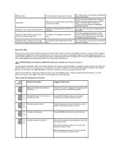
... on obtaining technical assistance. A successful POST ends with no beep code and no video during POST Solid green power indicator and no beep code but the system locks up...the back panel diagnostic LEDs, gives their probable causes, and offers suggested problem resolution(s), contact Dell Technical Assistance for instructions on the back of normal operation. See "Getting Help" for ... actions. yellow green yellow yellow Possible processor failure Reseat the processor(s) and the terminator card (if present), and restart the system to retest. An integrated system board device may...
... on obtaining technical assistance. A successful POST ends with no beep code and no video during POST Solid green power indicator and no beep code but the system locks up...the back panel diagnostic LEDs, gives their probable causes, and offers suggested problem resolution(s), contact Dell Technical Assistance for instructions on the back of normal operation. See "Getting Help" for ... actions. yellow green yellow yellow Possible processor failure Reseat the processor(s) and the terminator card (if present), and restart the system to retest. An integrated system board device may...

User Guide
Page 88
...necessary. l Consult the software documentation or contact the software manufacturer for technical assistance. l Make sure that you have a video card, reseat it and restart the system to retest. Whenever you change the operating environment parameters, you may also affect the successful... operation of terminate-and-stay-resident (TSR) programs has not resulted in the Dell Diagnostics. yellow green green green Other failure Contact Dell for detailed troubleshooting information on a particular program, see your computer system. Basic Checks: l Ensure...
...necessary. l Consult the software documentation or contact the software manufacturer for technical assistance. l Make sure that you have a video card, reseat it and restart the system to retest. Whenever you change the operating environment parameters, you may also affect the successful... operation of terminate-and-stay-resident (TSR) programs has not resulted in the Dell Diagnostics. yellow green green green Other failure Contact Dell for detailed troubleshooting information on a particular program, see your computer system. Basic Checks: l Ensure...
User Guide
Page 89
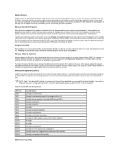
... the default settings. Add the TSR commands back into the start them . For example, if a network expansion card and an expanded-memory page frame are the cause of video mode or monitor. Then consult the following table to develop an alternative method of running that particular program-the creation... by serial port 1 Available Used by the diskette controller Used by the parallel port Used by the real-time clock (RTC) Used by the video graphics array (VGA) interface (optional) Available Available Used by the mouse port Used by the math coprocessor (if applicable) Used by the primary ...
... the default settings. Add the TSR commands back into the start them . For example, if a network expansion card and an expanded-memory page frame are the cause of video mode or monitor. Then consult the following table to develop an alternative method of running that particular program-the creation... by serial port 1 Available Used by the diskette controller Used by the parallel port Used by the real-time clock (RTC) Used by the video graphics array (VGA) interface (optional) Available Available Used by the mouse port Used by the math coprocessor (if applicable) Used by the primary ...

User Guide
Page 101
Back to Contents Page Technical Specifications: Dell™ OptiPlex™ GX150 System User's Guide Processor Memory System Information Graphics (Optional) and Video Audio Expansion Bus Drives Ports Key Combinations Controls and Indicators Power Physical Environmental Processor Microprocessor type ...accelerated graphics port (AGP) Embedded Intel Dynamic Video Memory Technology (DVMT) with optional 4-MB Graphics Performance Accelerator (GPA), or a 4X AGP card can be supported (low profile cards for the small mini-tower system) full-height cards [up to 512 MB Basic input/output ...
Back to Contents Page Technical Specifications: Dell™ OptiPlex™ GX150 System User's Guide Processor Memory System Information Graphics (Optional) and Video Audio Expansion Bus Drives Ports Key Combinations Controls and Indicators Power Physical Environmental Processor Microprocessor type ...accelerated graphics port (AGP) Embedded Intel Dynamic Video Memory Technology (DVMT) with optional 4-MB Graphics Performance Accelerator (GPA), or a 4X AGP card can be supported (low profile cards for the small mini-tower system) full-height cards [up to 512 MB Basic input/output ...
User Guide
Page 102
...for 1-inch-high enhanced integrated drive electronics (EIDE) hard drives headphones minijack on the rear input/output (I/O) panel; Display cache Graphics memory Video resolutions (display supports some or all of these resolutions) optional 4-MB, 133-MHz SDRAM Dynamically allocated from system memory 640 x 480 ... Devices AD1885 AC97 Codec 16 bit (analog-to-digital and digital-to 22.9 cm high (9 inches) 120 pins PCI expansion-card connector data width (maximum) 32 bits Drives Externally accessible bays: Small form-factor chassis Small desktop chassis Small mini-tower chassis Internally...
...for 1-inch-high enhanced integrated drive electronics (EIDE) hard drives headphones minijack on the rear input/output (I/O) panel; Display cache Graphics memory Video resolutions (display supports some or all of these resolutions) optional 4-MB, 133-MHz SDRAM Dynamically allocated from system memory 640 x 480 ... Devices AD1885 AC97 Codec 16 bit (analog-to-digital and digital-to 22.9 cm high (9 inches) 120 pins PCI expansion-card connector data width (maximum) 32 bits Drives Externally accessible bays: Small form-factor chassis Small desktop chassis Small mini-tower chassis Internally...
User Guide
Page 120
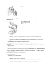
... a setup password has been assigned by lowering the securing lever on resetting the chassis intrusion detector. Insert the card into the notch on . Hook the back end of AGP card 2 I/O panel AGP video connector 3 AGP card clip lever a. b. 1 Hinged lever 3. Depending on your computer and peripherals to their electrical outlets, and turn them on...
... a setup password has been assigned by lowering the securing lever on resetting the chassis intrusion detector. Insert the card into the notch on . Hook the back end of AGP card 2 I/O panel AGP video connector 3 AGP card clip lever a. b. 1 Hinged lever 3. Depending on your computer and peripherals to their electrical outlets, and turn them on...


