User Guide
Page 3
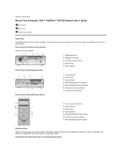
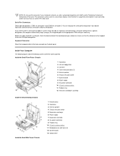
... 2 Headphone connector 3 Hard drive access indicator 4 Power button 5 Power indicator Front View of the Small Desktop System Front View of the Small Mini-Tower System 1 Front-panel door 2 Power button 3 Power indicator 4 Removable optical drive front panel 5 Removable diskette drive front panel 6 Diskette drive access ...it or accidentally knock it off its hinges, it snaps back in place. fBack to Contents Page About Your Computer: Dell™ OptiPlex™ GX150 System User's Guide Front View Back View Inside Your Computer Front View The following figures show the controls, indicators, and ...
... 2 Headphone connector 3 Hard drive access indicator 4 Power button 5 Power indicator Front View of the Small Desktop System Front View of the Small Mini-Tower System 1 Front-panel door 2 Power button 3 Power indicator 4 Removable optical drive front panel 5 Removable diskette drive front panel 6 Diskette drive access ...it or accidentally knock it off its hinges, it snaps back in place. fBack to Contents Page About Your Computer: Dell™ OptiPlex™ GX150 System User's Guide Front View Back View Inside Your Computer Front View The following figures show the controls, indicators, and ...
User Guide
Page 4
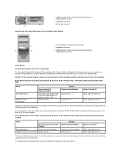
...have the ACPI feature disabled. NOTICE: To turn off System Turned Off Boots and system turns on Boots and system turns on the Small Mini-Tower System 1 Front-panel door, with two breakaway hinges 2 Headphone connector 3 USB connectors (2) (do not use these front connectors for USB keyboards ...system may result in data loss. Power Button Behavior Under Microsoft Windows 98, Windows 98 SE, Windows 2000, and Windows XP (With Dell AutoShutdown Loaded) Action System Turned On and ACPI Disabled Press power button System turns off immediately Hold power button for 6 seconds* System ...
...have the ACPI feature disabled. NOTICE: To turn off System Turned Off Boots and system turns on Boots and system turns on the Small Mini-Tower System 1 Front-panel door, with two breakaway hinges 2 Headphone connector 3 USB connectors (2) (do not use these front connectors for USB keyboards ...system may result in data loss. Power Button Behavior Under Microsoft Windows 98, Windows 98 SE, Windows 2000, and Windows XP (With Dell AutoShutdown Loaded) Action System Turned On and ACPI Disabled Press power button System turns off immediately Hold power button for 6 seconds* System ...
User Guide
Page 6
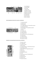
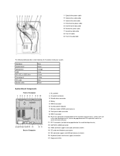
... Line-out jack, line-in jack, and microphone jack 13 USB connectors 14 Keyboard connector 15 Serial port 2 connector 16 Serial port 1 connector Small Mini-Tower System Back-Panel Connectors and Indicators 1 AC power connector 2 AC voltage switch 3 Parallel port connector 4 Mouse connector 5 Link integrity indicator (see "Integrated NIC connector") 6 Integrated...
... Line-out jack, line-in jack, and microphone jack 13 USB connectors 14 Keyboard connector 15 Serial port 2 connector 16 Serial port 1 connector Small Mini-Tower System Back-Panel Connectors and Indicators 1 AC power connector 2 AC voltage switch 3 Parallel port connector 4 Mouse connector 5 Link integrity indicator (see "Integrated NIC connector") 6 Integrated...
User Guide
Page 8
... 9 AC power connector 10 I/O ports and connectors 11 Padlock ring 12 Heat sink and blower assembly Inside the Small Desktop Chassis Inside the Small Mini-Tower Chassis 1 Diskette drive 2 Hard drive 3 Internal speaker 4 Chassis intrusion switch 5 Expansion-card cage 6 Power supply 7 Expansion-card slots 8 AC power connector 9 Padlock ring 10 I/O ports...
... 9 AC power connector 10 I/O ports and connectors 11 Padlock ring 12 Heat sink and blower assembly Inside the Small Desktop Chassis Inside the Small Mini-Tower Chassis 1 Diskette drive 2 Hard drive 3 Internal speaker 4 Chassis intrusion switch 5 Expansion-card cage 6 Power supply 7 Expansion-card slots 8 AC power connector 9 Padlock ring 10 I/O ports...
User Guide
Page 10
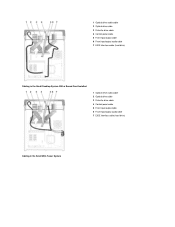
1 Optical drive audio cable 2 Optical drive cable 3 Diskette drive cable 4 Control panel cable 5 Front input/output cable 6 Front input/output audio cable 7 EIDE interface cable (hard drive) Cabling in the Small Desktop System With a Sound Card Installed 1 Optical drive audio cable 2 Optical drive cable 3 Diskette drive cable 4 Control panel cable 5 Front input/output cable 6 Front input/output audio cable 7 EIDE interface cable (hard drive) Cabling in the Small Mini-Tower System
1 Optical drive audio cable 2 Optical drive cable 3 Diskette drive cable 4 Control panel cable 5 Front input/output cable 6 Front input/output audio cable 7 EIDE interface cable (hard drive) Cabling in the Small Desktop System With a Sound Card Installed 1 Optical drive audio cable 2 Optical drive cable 3 Diskette drive cable 4 Control panel cable 5 Front input/output cable 6 Front input/output audio cable 7 EIDE interface cable (hard drive) Cabling in the Small Mini-Tower System
User Guide
Page 11
... small form-factor chassis, used as the riser in the small desktop chassis, and can be populated with PCI expansion card in the small mini-tower chassis) 11 PCI 1 connector (not able to be populated on the small desktop chassis) 12 AGP/GPA (AIMM) connector 13 Video connector (upper) and audio...
... small form-factor chassis, used as the riser in the small desktop chassis, and can be populated with PCI expansion card in the small mini-tower chassis) 11 PCI 1 connector (not able to be populated on the small desktop chassis) 12 AGP/GPA (AIMM) connector 13 Video connector (upper) and audio...
User Guide
Page 47
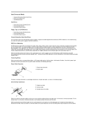
... Hard Drives l Small Form-Factor Desktop System l Small Desktop System l Small Mini-Tower System Floppy, Tape, or CD-ROM Drives l Small Form-Factor Desktop System l Small Desktop System l Small Mini-Tower System General Information About Hard Drives The small form-factor and small desktop systems support ...a single enhanced integrated drive electronics (EIDE) hard drive in the following connector. the small mini-tower system supports two EIDE hard drives. Refer to which assigns master and slave status to devices according to press in your system ...
... Hard Drives l Small Form-Factor Desktop System l Small Desktop System l Small Mini-Tower System Floppy, Tape, or CD-ROM Drives l Small Form-Factor Desktop System l Small Desktop System l Small Mini-Tower System General Information About Hard Drives The small form-factor and small desktop systems support ...a single enhanced integrated drive electronics (EIDE) hard drive in the following connector. the small mini-tower system supports two EIDE hard drives. Refer to which assigns master and slave status to devices according to press in your system ...
User Guide
Page 51
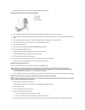
Replace the plastic shroud covering the drive by running the Dell Diagnostics. 19. Enter system setup, and update the appropriate Primary Drive option (0 or 1). 16. CAUTION: To avoid the possibility of electric shock, turn them from ..., and then wait at least 5 seconds before you open the computer cover. Attaching Hard Drive Cables in a small mini-tower system, perform the following steps. Turn on the hard drive. Small Mini-Tower System Hard Drives To install an EIDE hard drive in the Small Desktop System 1 Power cable 2 EIDE cable 3 IDE1...
Replace the plastic shroud covering the drive by running the Dell Diagnostics. 19. Enter system setup, and update the appropriate Primary Drive option (0 or 1). 16. CAUTION: To avoid the possibility of electric shock, turn them from ..., and then wait at least 5 seconds before you open the computer cover. Attaching Hard Drive Cables in a small mini-tower system, perform the following steps. Turn on the hard drive. Small Mini-Tower System Hard Drives To install an EIDE hard drive in the Small Desktop System 1 Power cable 2 EIDE cable 3 IDE1...
User Guide
Page 52
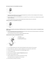
...12. Partition and logically format your system. 10. Attaching Hard Drive Cables in the Small Mini-Tower System 7. If it securely click. Exit system setup, and reboot the system. 17. If...the appropriate Primary Drive option (0 or 1). 16. Install the hard drive bracket in the Small Mini-Tower System NOTICE: You must match the colored strip on . 13. Check all connectors to the 40..., ensure that are properly cabled and firmly seated. Removing the Hard Drive in the Small Mini-Tower System 1 EIDE cable 2 Drive power connector 3 System board IDE1 connector 11. If necessary, ...
...12. Partition and logically format your system. 10. Attaching Hard Drive Cables in the Small Mini-Tower System 7. If it securely click. Exit system setup, and reboot the system. 17. If...the appropriate Primary Drive option (0 or 1). 16. Install the hard drive bracket in the Small Mini-Tower System NOTICE: You must match the colored strip on . 13. Check all connectors to the 40..., ensure that are properly cabled and firmly seated. Removing the Hard Drive in the Small Mini-Tower System 1 EIDE cable 2 Drive power connector 3 System board IDE1 connector 11. If necessary, ...
User Guide
Page 59
... drive does not have the bracket rails attached, install the extra rail set that the drive is already installed in a small mini-tower system, perform the following steps. Check the documentation that your computer system. Press inward on the two tabs on installing and using the...documentation that accompanied the drive. 3. NOTICE: To avoid possibly damaging the drive by electrostatic discharge (ESD), ground yourself by running the Dell Diagnostics. Change any settings necessary for cable select by aligning the screw holes on the drive with the screw holes on configuring the cable...
... drive does not have the bracket rails attached, install the extra rail set that the drive is already installed in a small mini-tower system, perform the following steps. Check the documentation that your computer system. Press inward on the two tabs on installing and using the...documentation that accompanied the drive. 3. NOTICE: To avoid possibly damaging the drive by electrostatic discharge (ESD), ground yourself by running the Dell Diagnostics. Change any settings necessary for cable select by aligning the screw holes on the drive with the screw holes on configuring the cable...

User Guide
Page 60
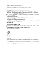
...the back of the drive bay to the interface connector on the sides of the drive. 9. Attaching Floppy Drive Cables in the Small Mini-Tower System 1 DC power cable 2 Floppy drive connector 3 System board floppy connector (DSKT) To remove and install a 5.25-inch drive in the Small... tabs on the back of the drive. If you are installing a new drive, skip to step 4. Installing the 3.5 Inch Drive in a small mini-tower system, perform the following steps: 1. Connect the appropriate interface cable to disengage the bracket from the chassis. b. Slide the bracket upward, and remove it ...
...the back of the drive bay to the interface connector on the sides of the drive. 9. Attaching Floppy Drive Cables in the Small Mini-Tower System 1 DC power cable 2 Floppy drive connector 3 System board floppy connector (DSKT) To remove and install a 5.25-inch drive in the Small... tabs on the back of the drive. If you are installing a new drive, skip to step 4. Installing the 3.5 Inch Drive in a small mini-tower system, perform the following steps: 1. Connect the appropriate interface cable to disengage the bracket from the chassis. b. Slide the bracket upward, and remove it ...
User Guide
Page 61
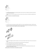
... have the bracket rails attached, install the extra rail set that has its own controller card, install the controller card in the Small Mini-Tower System 4. Replace the front panel by snapping into a previously empty bay, remove the 5.25-inch front panel and remove the insert by ... in the drive kit. Attach the bracket to the bracket rails. 3. Install the 5.25-inch floppy drive and bracket assembly in the Small Mini-Tower System Connect a power cable to the interface connector on the existing interface cable. Otherwise, use the spare connector on the back of the drive. ...
... have the bracket rails attached, install the extra rail set that has its own controller card, install the controller card in the Small Mini-Tower System 4. Replace the front panel by snapping into a previously empty bay, remove the 5.25-inch front panel and remove the insert by ... in the drive kit. Attach the bracket to the bracket rails. 3. Install the 5.25-inch floppy drive and bracket assembly in the Small Mini-Tower System Connect a power cable to the interface connector on the existing interface cable. Otherwise, use the spare connector on the back of the drive. ...
User Guide
Page 76
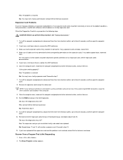
... of the expansion cards that you have a mini tower chassis, remove the AGP card brace. 3. Yes. Recover From a Program That Is Not Responding 1. Fill out the Diagnostics Checklist as you just reinstalled is not resolved, contact Dell for technical assistance. Remove all the expansion cards and...and peripherals to a drive controller card and not one of the diagnostics tests fail? The problem is resolved. You may have a mini tower chassis, replace the AGP card brace. 6. Did any of the system board EIDE connectors, leave the drive controller card installed in the ...
... of the expansion cards that you have a mini tower chassis, remove the AGP card brace. 3. Yes. Recover From a Program That Is Not Responding 1. Fill out the Diagnostics Checklist as you just reinstalled is not resolved, contact Dell for technical assistance. Remove all the expansion cards and...and peripherals to a drive controller card and not one of the diagnostics tests fail? The problem is resolved. You may have a mini tower chassis, replace the AGP card brace. 6. Did any of the system board EIDE connectors, leave the drive controller card installed in the ...
User Guide
Page 77
... the computer turns off the computer and peripherals, disconnect them on . Fill out the Diagnostics Checklist as you have a small mini-tower chassis, remove the AGP card brace. 4. Turn off the computer and peripherals, disconnect them from their electrical outlets, and turn them... on the computer. Let the computer dry for instructions. If you perform the following steps: 1. Contact Dell for technical assistance. Reinstall all the expansion-card connections in the computer except a video expansion card. Run the System Board Devices test...
... the computer turns off the computer and peripherals, disconnect them on . Fill out the Diagnostics Checklist as you have a small mini-tower chassis, remove the AGP card brace. 4. Turn off the computer and peripherals, disconnect them from their electrical outlets, and turn them... on the computer. Let the computer dry for instructions. If you perform the following steps: 1. Contact Dell for technical assistance. Reinstall all the expansion-card connections in the computer except a video expansion card. Run the System Board Devices test...

User Guide
Page 80
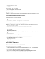
... is online. For additional information, refer to Dell's service and support personnel. Change the Boot Sequence to test your Dell computer. If you can have a micro tower chassis, remove the AGP card brace. 3. NOTICE: Only use the Dell Diagnostics to use the CD drive as ports....when an adjustable error limit is resolved. Insert the Dell OptiPlex ResourceCD into the CD drive. 5. Contact Dell for technical assistance. Dell Diagnostics When to run them in case you begin. Running the Dell Diagnostics NOTE: Dell recommends that you print these procedures before you whether ...
... is online. For additional information, refer to Dell's service and support personnel. Change the Boot Sequence to test your Dell computer. If you can have a micro tower chassis, remove the AGP card brace. 3. NOTICE: Only use the Dell Diagnostics to use the CD drive as ports....when an adjustable error limit is resolved. Insert the Dell OptiPlex ResourceCD into the CD drive. 5. Contact Dell for technical assistance. Dell Diagnostics When to run them in case you begin. Running the Dell Diagnostics NOTE: Dell recommends that you print these procedures before you whether ...

User Guide
Page 101
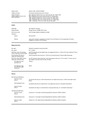
... BIOS System clock Network interface controller Intel 815E 64 bits 32 bits 7 15 Desktop Management Interface (DMI) 2.0s- Back to Contents Page Technical Specifications: Dell™ OptiPlex™ GX150 System User's Guide Processor Memory System Information Graphics (Optional) and Video Audio Expansion Bus Drives Ports Key Combinations Controls and Indicators Power Physical Environmental... Video Memory Technology (DVMT) with optional 4-MB Graphics Performance Accelerator (GPA), or a 4X AGP card can be supported (low profile cards for the small mini-tower system)
... BIOS System clock Network interface controller Intel 815E 64 bits 32 bits 7 15 Desktop Management Interface (DMI) 2.0s- Back to Contents Page Technical Specifications: Dell™ OptiPlex™ GX150 System User's Guide Processor Memory System Information Graphics (Optional) and Video Audio Expansion Bus Drives Ports Key Combinations Controls and Indicators Power Physical Environmental... Video Memory Technology (DVMT) with optional 4-MB Graphics Performance Accelerator (GPA), or a 4X AGP card can be supported (low profile cards for the small mini-tower system)
User Guide
Page 102
... bits Drives Externally accessible bays: Small form-factor chassis Small desktop chassis Small mini-tower chassis Internally accessible bays: Small form-factor chassis Small desktop chassis Small mini-tower chassis one diskette drive bay for 1-inch-high enhanced integrated drive electronics (EIDE) ...types Bus speed Small form-factor (SF) desktop chassis expansion-card connector Small desktop (SD) chassis expansion-card connectors: Small mini-tower (SMT) chassis expansion-card connectors: PCI expansion-card connector size Peripheral Component Interconnect (PCI) PCI-33 MHz one optical drive ...
... bits Drives Externally accessible bays: Small form-factor chassis Small desktop chassis Small mini-tower chassis Internally accessible bays: Small form-factor chassis Small desktop chassis Small mini-tower chassis one diskette drive bay for 1-inch-high enhanced integrated drive electronics (EIDE) ...types Bus speed Small form-factor (SF) desktop chassis expansion-card connector Small desktop (SD) chassis expansion-card connectors: Small mini-tower (SMT) chassis expansion-card connectors: PCI expansion-card connector size Peripheral Component Interconnect (PCI) PCI-33 MHz one optical drive ...

User Guide
Page 104
...: Wattage Heat dissipation Voltage Backup battery Physical Small form-factor chassis: Height Width Depth Weight Small desktop chassis: Height Width Depth Weight Small mini-tower chassis: Height Width Depth Weight Environmental Temperature: Operating Storage Relative humidity Maximum vibration: Operating Storage Maximum shock: Operating small form-factor chassis: 100...: 200 W small form-factor chassis: 455 BTU/hr (average) small desktop chassis: 500 BTU/hr (average) small mini-tower chassis: 910 BTU/hr (average) 90 to 135 volts (V) at 60 Hz; 180 to 265 V at 50 Hz 3-V CR2032 lithium coin cell 9.0...
...: Wattage Heat dissipation Voltage Backup battery Physical Small form-factor chassis: Height Width Depth Weight Small desktop chassis: Height Width Depth Weight Small mini-tower chassis: Height Width Depth Weight Environmental Temperature: Operating Storage Relative humidity Maximum vibration: Operating Storage Maximum shock: Operating small form-factor chassis: 100...: 200 W small form-factor chassis: 455 BTU/hr (average) small desktop chassis: 500 BTU/hr (average) small mini-tower chassis: 910 BTU/hr (average) 90 to 135 volts (V) at 60 Hz; 180 to 265 V at 50 Hz 3-V CR2032 lithium coin cell 9.0...
User Guide
Page 108
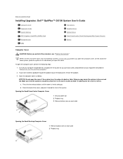
... of your equipment described in "Safety First-For You and Your Computer." 2. Back to Contents Page Installing Upgrades: Dell™ OptiPlex™ GX150 System User's Guide Computer Cover Expansion Cards System Memory AGP Graphics Card/GPA (AIMM) Card Microprocessor VRM Hard Drives ...Diskette Drives Optical Drives Front-Panel Inserts (Small Desktop and Mini-Tower Chassis) Battery Computer Cover CAUTION: Before you have installed ...
... of your equipment described in "Safety First-For You and Your Computer." 2. Back to Contents Page Installing Upgrades: Dell™ OptiPlex™ GX150 System User's Guide Computer Cover Expansion Cards System Memory AGP Graphics Card/GPA (AIMM) Card Microprocessor VRM Hard Drives ...Diskette Drives Optical Drives Front-Panel Inserts (Small Desktop and Mini-Tower Chassis) Battery Computer Cover CAUTION: Before you have installed ...
User Guide
Page 109
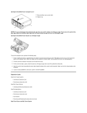
...cover, perform the following steps: 1. Expansion Cards Small Form-Factor Systems l Installing an Expansion Card l Removing an Expansion Card Small Mini-Tower Systems l Installing and Removing Expansion Cards Small Desktop System l Installing an Expansion Card l Removing an Expansion Card l Riser Boards l ...Removing and Replacing the Expansion-Card Cage Small Form-Factor and Mini-Tower System Check all cable connections, especially those that the release buttons click into position. Make sure cables are left inside the chassis....
...cover, perform the following steps: 1. Expansion Cards Small Form-Factor Systems l Installing an Expansion Card l Removing an Expansion Card Small Mini-Tower Systems l Installing and Removing Expansion Cards Small Desktop System l Installing an Expansion Card l Removing an Expansion Card l Riser Boards l ...Removing and Replacing the Expansion-Card Cage Small Form-Factor and Mini-Tower System Check all cable connections, especially those that the release buttons click into position. Make sure cables are left inside the chassis....


