User Guide
Page 19
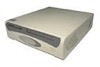
...the other precautions in the chassis. Check the documentation that accompanied the drive to Contents Page Diskette, Tape, and CD-ROM Drives: Dell™ OptiPlex™ GX100 System User's Guide Installing a CD-ROM Drive in a Small-Form-Factor Chassis Installing a Diskette, Tape, or CD-ROM Drive ...in a Low-Profile Chassis Installing a Diskette, Tape, or CD-ROM Drive in a Mini Tower Chassis Connecting Drives Installing a CD-ROM Drive in a Small-...
...the other precautions in the chassis. Check the documentation that accompanied the drive to Contents Page Diskette, Tape, and CD-ROM Drives: Dell™ OptiPlex™ GX100 System User's Guide Installing a CD-ROM Drive in a Small-Form-Factor Chassis Installing a Diskette, Tape, or CD-ROM Drive ...in a Low-Profile Chassis Installing a Diskette, Tape, or CD-ROM Drive in a Mini Tower Chassis Connecting Drives Installing a CD-ROM Drive in a Small-...
User Guide
Page 22
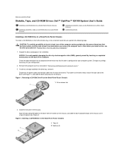
... Secondary Drive n" for installation. NOTICE: To avoid possibly damaging the drive by electromagnetic static (EMS), ground yourself by running the Dell Diagnostics. Change any peripherals, disconnect them on installing and using the tape drive software. Verify that accompanied the drive. Check the...controller card, depending on the drive. If your new diskette drive. Installing a Diskette, Tape, or CD-ROM Drive in a Mini Tower Chassis To install a diskette, tape, or CD-ROM drive in "Inside Your Computer"). Connect the interface cable to reflect the size ...
... Secondary Drive n" for installation. NOTICE: To avoid possibly damaging the drive by electromagnetic static (EMS), ground yourself by running the Dell Diagnostics. Change any peripherals, disconnect them on installing and using the tape drive software. Verify that accompanied the drive. Check the...controller card, depending on the drive. If your new diskette drive. Installing a Diskette, Tape, or CD-ROM Drive in a Mini Tower Chassis To install a diskette, tape, or CD-ROM drive in "Inside Your Computer"). Connect the interface cable to reflect the size ...
User Guide
Page 23
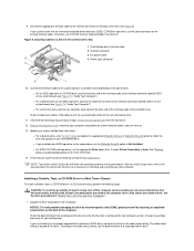
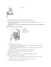
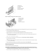
... (see Figure 11). Make sure that both bracket tabs snap into place. a. Attaching the Drive Bracket to the replacement drive. Remove the front bezel (mini tower only) as instructed in which the holes are numbered (the holes are replacing it, disconnect the DC power cable and interface cable from the bracket...
... (see Figure 11). Make sure that both bracket tabs snap into place. a. Attaching the Drive Bracket to the replacement drive. Remove the front bezel (mini tower only) as instructed in which the holes are numbered (the holes are replacing it, disconnect the DC power cable and interface cable from the bracket...
User Guide
Page 24
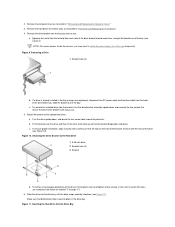
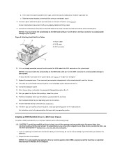
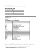
... (see Figure 7 in System Setup. l For a diskette drive, connect the cable from the front bezel. 11. Replace the front bezel (mini tower only). 12. l For EIDE CD-ROM and tape drives, set the appropriate Secondary Drive option (0 or 1) to the system board. Verify that... Drive or Tape Drive Cables 1 Interface cable 2 Power cable 3 Power input connector 4 Interface connector 9. Update your system works correctly by running the Dell Diagnostics. Connect a DC power cable to your system. Figure 12. l For a diskette drive, update the appropriate Diskette Drive option (A or B) to...
... (see Figure 7 in System Setup. l For a diskette drive, connect the cable from the front bezel. 11. Replace the front bezel (mini tower only). 12. l For EIDE CD-ROM and tape drives, set the appropriate Secondary Drive option (0 or 1) to the system board. Verify that... Drive or Tape Drive Cables 1 Interface cable 2 Power cable 3 Power input connector 4 Interface connector 9. Update your system works correctly by running the Dell Diagnostics. Connect a DC power cable to your system. Figure 12. l For a diskette drive, update the appropriate Diskette Drive option (A or B) to...
User Guide
Page 26
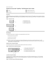
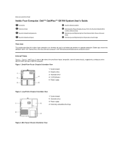
... this step due to Contents Page Expansion Cards: Dell™ OptiPlex™ GX100 System User's Guide Overview Riser Boards Installing an Expansion Card Removing an Expansion Card Overview OptiPlex GX100 systems can accommodate a mix of 32-bit Peripheral Component Interconnect (PCI) expansion cards and, optionally, 16-...slots. Figure 3. See Figure 1 for each chassis: l Small-form-factor chassis riser board l Low-profile chassis riser board l Mini tower chassis riser board NOTE: If you order other ISA riser boards. Back to the broad range of the expansion cards. Expansion Cards 1...
... this step due to Contents Page Expansion Cards: Dell™ OptiPlex™ GX100 System User's Guide Overview Riser Boards Installing an Expansion Card Removing an Expansion Card Overview OptiPlex GX100 systems can accommodate a mix of 32-bit Peripheral Component Interconnect (PCI) expansion cards and, optionally, 16-...slots. Figure 3. See Figure 1 for each chassis: l Small-form-factor chassis riser board l Low-profile chassis riser board l Mini tower chassis riser board NOTE: If you order other ISA riser boards. Back to the broad range of the expansion cards. Expansion Cards 1...
User Guide
Page 27
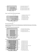
... 3 ISA expansion slot 2 (ISA2) 4 Remote Wakeup header (WOL) 5 PCI expansion slot 1 (PCI1) 6 PCI expansion slot 2 (PCI2) Mini Tower Chassis Riser Board The mini tower chassis is available with either a PCI riser board (see Figure 5) or a PCI/ISA riser board (see Figure 6). Mini...) 1 Auxiliary power indicator (AUX_LED) 2 PCI expansion-card connector 5 (PCI5) 3 Remote Wakeup header (WOL) 4 PCI expansion-card connector 1 (PCI1) Figure 6. Mini Tower Chassis PCI/ISA Riser Board (Optional) 1 PCI expansion slot 1 (PCI1) 2 PCI expansion slot 2 (PCI2) 3 PCI expansion slot 3 (PCI3) 4 PCI expansion slot...
... 3 ISA expansion slot 2 (ISA2) 4 Remote Wakeup header (WOL) 5 PCI expansion slot 1 (PCI1) 6 PCI expansion slot 2 (PCI2) Mini Tower Chassis Riser Board The mini tower chassis is available with either a PCI riser board (see Figure 5) or a PCI/ISA riser board (see Figure 6). Mini...) 1 Auxiliary power indicator (AUX_LED) 2 PCI expansion-card connector 5 (PCI5) 3 Remote Wakeup header (WOL) 4 PCI expansion-card connector 1 (PCI1) Figure 6. Mini Tower Chassis PCI/ISA Riser Board (Optional) 1 PCI expansion slot 1 (PCI1) 2 PCI expansion slot 2 (PCI2) 3 PCI expansion slot 3 (PCI3) 4 PCI expansion slot...
User Guide
Page 28
... Chassis CAUTION: Some network cards automatically start up the system when they are connected. Save the screw for the smallform-factor, low-profile, and mini tower chassis, respectively). Insert the card's edge connector firmly into the connector until it is full-length, insert the front end of the card into the...
... Chassis CAUTION: Some network cards automatically start up the system when they are connected. Save the screw for the smallform-factor, low-profile, and mini tower chassis, respectively). Insert the card's edge connector firmly into the connector until it is full-length, insert the front end of the card into the...
User Guide
Page 29
... and reset Chassis Intrusion to Off. While in System Setup, if you installed an entry-level OptiPlex sound card, change the setting for information on the screen at least 5 seconds before you removed in a Mini Tower Chassis 1 Expansion-card cage 2 Card-edge connector 3 Expansion card 4 Riser board 5 Expansion-card connector 5. 1 Expansion card...
... and reset Chassis Intrusion to Off. While in System Setup, if you installed an entry-level OptiPlex sound card, change the setting for information on the screen at least 5 seconds before you removed in a Mini Tower Chassis 1 Expansion-card cage 2 Card-edge connector 3 Expansion card 4 Riser board 5 Expansion-card connector 5. 1 Expansion card...

User Guide
Page 35
In the mini tower chassis, you can install up to two EIDE drives (one of which must be 1 inch high or less) in your system supports up to Contents Page Hard-Disk Drives: Dell™ OptiPlex™ GX100 System User's Guide General Information About EIDE Hard-Disk Drives Installing... an EIDE Hard-Disk Drive in a Low-Profile Chassis Installing an EIDE Hard-Disk Drive in a Small-Form-Factor Chassis Installing an EIDE Hard-Disk Drive in a Mini Tower Chassis General...
In the mini tower chassis, you can install up to two EIDE drives (one of which must be 1 inch high or less) in your system supports up to Contents Page Hard-Disk Drives: Dell™ OptiPlex™ GX100 System User's Guide General Information About EIDE Hard-Disk Drives Installing... an EIDE Hard-Disk Drive in a Low-Profile Chassis Installing an EIDE Hard-Disk Drive in a Small-Form-Factor Chassis Installing an EIDE Hard-Disk Drive in a Mini Tower Chassis General...
User Guide
Page 39
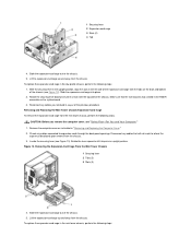
...to avoid possible damage to the power input connector on the back of the drive (see Figure 7 in a mini tower chassis, perform the following steps: CAUTION: To avoid the possibility of the computer. Attaching Hard-Disk Drive Cables 1 ... the System Setup settings, reboot the system. 16. Installing an EIDE Hard-Disk Drive in a Mini Tower Chassis To install an EIDE hard-disk drive in "Inside Your Computer." 11. See the documentation for installation...drive by electromagnetic static (EMS), ground yourself by running the Dell Diagnostics. 18. Figure 8. For You and Your Computer." 1.
...to avoid possible damage to the power input connector on the back of the drive (see Figure 7 in a mini tower chassis, perform the following steps: CAUTION: To avoid the possibility of the computer. Attaching Hard-Disk Drive Cables 1 ... the System Setup settings, reboot the system. 16. Installing an EIDE Hard-Disk Drive in a Mini Tower Chassis To install an EIDE hard-disk drive in "Inside Your Computer." 11. See the documentation for installation...drive by electromagnetic static (EMS), ground yourself by running the Dell Diagnostics. 18. Figure 8. For You and Your Computer." 1.
User Guide
Page 46
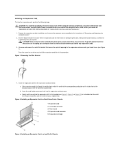
... of the insert into the opening , insert the two ringtabs (see Figure 1). Back to Contents Page Front-Panel Inserts: Dell™ OptiPlex™ GX100 System User's Guide Low-Profile Chassis Front-Panel Inserts Mini Tower Chassis Front-Panel Inserts Low-Profile Chassis Front-Panel Inserts Empty drive bays contain a front-panel insert to protect...
... of the insert into the opening , insert the two ringtabs (see Figure 1). Back to Contents Page Front-Panel Inserts: Dell™ OptiPlex™ GX100 System User's Guide Low-Profile Chassis Front-Panel Inserts Mini Tower Chassis Front-Panel Inserts Low-Profile Chassis Front-Panel Inserts Empty drive bays contain a front-panel insert to protect...

User Guide
Page 47
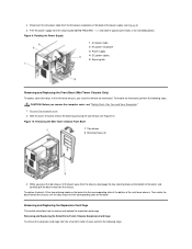
... posts on the inside of the bay opening, and firmly press both ends of the insert into the opening . Removing the Front-Panel Insert (Mini Tower Chassis) 1 Ring tabs (2) 2 Posts (2) 3 Computer cover To replace a front-panel insert for removing a 5.25-inch insert. 2. Insert the two ring-...the plastic insert out of its opening . To remove the insert covering a 5.25-inch bay, perform the following steps: 1. Figure 3. Mini Tower Chassis Front-Panel Inserts Empty drive bays contain a front-panel insert to protect the inside of the computer from their electrical outlets. Inside the ...
... posts on the inside of the bay opening, and firmly press both ends of the insert into the opening . Removing the Front-Panel Insert (Mini Tower Chassis) 1 Ring tabs (2) 2 Posts (2) 3 Computer cover To replace a front-panel insert for removing a 5.25-inch insert. 2. Insert the two ring-...the plastic insert out of its opening . To remove the insert covering a 5.25-inch bay, perform the following steps: 1. Figure 3. Mini Tower Chassis Front-Panel Inserts Empty drive bays contain a front-panel insert to protect the inside of the computer from their electrical outlets. Inside the ...
User Guide
Page 48
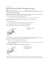
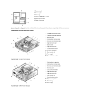
... 2. Low-Profile Chassis Orientation View 1 System board 2 Hard-disk drive 3 Power supply 4 Externally accessible drive bays Figure 3. Mini Tower Chassis Orientation View Figure 1. Before you to Contents Page Inside Your Computer: Dell™ OptiPlex™ GX100 System User's Guide Overview Internal Views System Board Components System Board Jumpers System Board Labels Rotating the Power...
... 2. Low-Profile Chassis Orientation View 1 System board 2 Hard-disk drive 3 Power supply 4 Externally accessible drive bays Figure 3. Mini Tower Chassis Orientation View Figure 1. Before you to Contents Page Inside Your Computer: Dell™ OptiPlex™ GX100 System User's Guide Overview Internal Views System Board Components System Board Jumpers System Board Labels Rotating the Power...
User Guide
Page 49
... slot 9 I /O ports and connectors 10 AC power receptacle 11 Security cable slot 12 Power supply 13 Chassis intrusion switch Figure 5. Inside the Mini Tower Chassis 1 System board 2 Power supply 3 Drive cage 4 Internal hard-disk drive bracket 5 Expansion-card cage 6 Bottom of computer Figure 4, Figure... 5, and Figure 6 show the small-form-factor, low-profile, and mini tower chassis, respectively, with the cover removed. Inside the Small-Form-Factor Chassis 1 CD-ROM drive interface cable 2 Externally accessible upper bay 3 Hard...
... slot 9 I /O ports and connectors 10 AC power receptacle 11 Security cable slot 12 Power supply 13 Chassis intrusion switch Figure 5. Inside the Mini Tower Chassis 1 System board 2 Power supply 3 Drive cage 4 Internal hard-disk drive bracket 5 Expansion-card cage 6 Bottom of computer Figure 4, Figure... 5, and Figure 6 show the small-form-factor, low-profile, and mini tower chassis, respectively, with the cover removed. Inside the Small-Form-Factor Chassis 1 CD-ROM drive interface cable 2 Externally accessible upper bay 3 Hard...
User Guide
Page 51
...Mouse connector Control panel connector Parallel port connector; NOTICE: Make sure your system or unpredictable results may have to rotate the mini tower chassis system power supply out of their functions. Table 1. To rotate the power supply, perform the following steps. Remove the ... connector Riser board connector Serial port connectors Universal Serial Bus (USB) connectors Rotating the Power Supply Away From the System Board (Mini Tower Chassis Only) To access some components on the system board, and it down over the pins. unjumpered System password features are small ...
...Mouse connector Control panel connector Parallel port connector; NOTICE: Make sure your system or unpredictable results may have to rotate the mini tower chassis system power supply out of their functions. Table 1. To rotate the power supply, perform the following steps. Remove the ... connector Riser board connector Serial port connectors Universal Serial Bus (USB) connectors Rotating the Power Supply Away From the System Board (Mini Tower Chassis Only) To access some components on the system board, and it down over the pins. unjumpered System password features are small ...
User Guide
Page 52
... Then rotate the bezel toward the chassis until it upward until the tabs snap into their corresponding slots on the back of the mini tower chassis. Remove the computer cover. 2. Removing and Replacing the Small-Form-Factor Chassis Expansion-Card Cage To remove the expansion-card cage ... 1 AC power cable 2 AC power receptacle 3 Power supply 4 DC power cables 5 Securing tab Removing and Replacing the Front Bezel (Mini Tower Chassis Only) To access some drive bays in its extended position. Removing and Replacing the Expansion-Card Cage This section describes how to remove and...
... Then rotate the bezel toward the chassis until it upward until the tabs snap into their corresponding slots on the back of the mini tower chassis. Remove the computer cover. 2. Removing and Replacing the Small-Form-Factor Chassis Expansion-Card Cage To remove the expansion-card cage ... 1 AC power cable 2 AC power receptacle 3 Power supply 4 DC power cables 5 Securing tab Removing and Replacing the Front Bezel (Mini Tower Chassis Only) To access some drive bays in its extended position. Removing and Replacing the Expansion-Card Cage This section describes how to remove and...
User Guide
Page 54
...-card cage into place. 2. Reconnect any cables you remove the computer cover, see Figure 13). Removing and Replacing the Mini Tower Chassis Expansion-Card Cage To remove the expansion-card cage from the chassis. Remove the computer cover as instructed in the RISER connector... upright position. 1 Securing lever 2 Expansion-card cage 3 Slots (2) 4 Tab 4. Rotate the lever upward until it stops in the mini tower chassis, perform the following steps: 1. CAUTION: Before you removed in the low-profile chassis, perform the following steps: Disconnect any cables connected ...
...-card cage into place. 2. Reconnect any cables you remove the computer cover, see Figure 13). Removing and Replacing the Mini Tower Chassis Expansion-Card Cage To remove the expansion-card cage from the chassis. Remove the computer cover as instructed in the RISER connector... upright position. 1 Securing lever 2 Expansion-card cage 3 Slots (2) 4 Tab 4. Rotate the lever upward until it stops in the mini tower chassis, perform the following steps: 1. CAUTION: Before you removed in the low-profile chassis, perform the following steps: Disconnect any cables connected ...
User Guide
Page 58
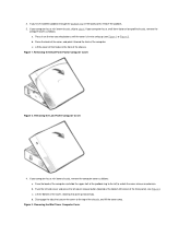
b. Figure 1. If your computer has a mini tower chassis, remove the computer cover as follows: a. Raise the back of the cover, and pivot it to the left corner of the padlock ring to ... cover away. Figure 3. If your computer has a small-form-factor or low-profile chassis, remove the computer cover as follows: a. c. If your computer has a mini tower chassis, skip to the top of the computer. Removing the Mini Tower Computer Cover 2. Press in on the back panel, remove the padlock. 3.
b. Figure 1. If your computer has a mini tower chassis, remove the computer cover as follows: a. Raise the back of the cover, and pivot it to the left corner of the padlock ring to ... cover away. Figure 3. If your computer has a small-form-factor or low-profile chassis, remove the computer cover as follows: a. c. If your computer has a mini tower chassis, skip to the top of the computer. Removing the Mini Tower Computer Cover 2. Press in on the back panel, remove the padlock. 3.
User Guide
Page 59
... To replace the computer cover, perform the following steps: 1. Check all cable connections, especially those that might have come loose during your computer has a mini tower chassis, skip to see that they will prevent the cover from closing properly. 2. Face the front of the chassis and into position.
... To replace the computer cover, perform the following steps: 1. Check all cable connections, especially those that might have come loose during your computer has a mini tower chassis, skip to see that they will prevent the cover from closing properly. 2. Face the front of the chassis and into position.

User Guide
Page 60
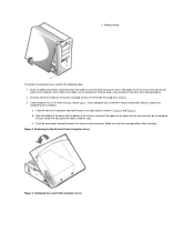
... a. Remove the computer cover. 3. 4. While aligning the top of the cover with the top of the cover to submerge your computer has a mini tower chassis, replace the computer cover as shown in the computer except a drive controller card and video expansion card. 5. With both hands, press against the bottom... disconnect any attached peripherals, and disconnect all expansion cards installed in Figure 6. Remove all the AC power cables from the computer. Replacing the Mini Tower Computer Cover 1 Hook 2 Recessed slot Troubleshooting a Wet Computer Liquids can also cause damage.
... a. Remove the computer cover. 3. 4. While aligning the top of the cover with the top of the cover to submerge your computer has a mini tower chassis, replace the computer cover as shown in the computer except a drive controller card and video expansion card. 5. With both hands, press against the bottom... disconnect any attached peripherals, and disconnect all expansion cards installed in Figure 6. Remove all the AC power cables from the computer. Replacing the Mini Tower Computer Cover 1 Hook 2 Recessed slot Troubleshooting a Wet Computer Liquids can also cause damage.


