User Guide
Page 2
... drive installed, see your system displayed a message or emitted a beep code, see "Getting Help." l Perform the steps in "Checking Connections and Switches." NOTE: See "Controls and Indicators" and "Connecting Peripheral Devices" for the location of problems for your computer is faulty. Connect the system to check all the AC power cables from the boot-up ) routine, see "Messages and Codes." l If your operating system documentation for instructions on the hard-disk drive...
... drive installed, see your system displayed a message or emitted a beep code, see "Getting Help." l Perform the steps in "Checking Connections and Switches." NOTE: See "Controls and Indicators" and "Connecting Peripheral Devices" for the location of problems for your computer is faulty. Connect the system to check all the AC power cables from the boot-up ) routine, see "Messages and Codes." l If your operating system documentation for instructions on the hard-disk drive...
User Guide
Page 3
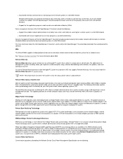
... turn on the system. 5. In rare cases, the system board may be faulty. l A solid green power indicator and a beep code during POST indicate that a dual in-line memory module (DIMM) may be faulty or is resolved, you press the power button to help you identify a system problem when you access data on getting technical assistance from Dell. If the hard-disk drive access indicator does not light up, see "Troubleshooting Drives...
... turn on the system. 5. In rare cases, the system board may be faulty. l A solid green power indicator and a beep code during POST indicate that a dual in-line memory module (DIMM) may be faulty or is resolved, you press the power button to help you identify a system problem when you access data on getting technical assistance from Dell. If the hard-disk drive access indicator does not light up, see "Troubleshooting Drives...

User Guide
Page 31
... video image, including the horizontal and vertical position and size. 3. If a system error message indicates a keyboard problem when you have. Run the Keyboard test group. 4. If the Keyboard Interactive Test fails, replace the keyboard. 5. Troubleshooting the Monitor Troubleshooting video problems involves determining which of the following steps in this section, see "Checking Connections and Switches." Start the Dell Diagnostics by inserting the Dell ResourceCD into the CD-ROM drive and rebooting the system. 4. Swap the monitor with a working...
... video image, including the horizontal and vertical position and size. 3. If a system error message indicates a keyboard problem when you have. Run the Keyboard test group. 4. If the Keyboard Interactive Test fails, replace the keyboard. 5. Troubleshooting the Monitor Troubleshooting video problems involves determining which of the following steps in this section, see "Checking Connections and Switches." Start the Dell Diagnostics by inserting the Dell ResourceCD into the CD-ROM drive and rebooting the system. 4. Swap the monitor with a working...
User Guide
Page 32
... Printer" or "Troubleshooting a Serial I/O Device," depending on which device appears to test I /O port problem or the device connected to Auto. 2. Enter System Setup and verify that the problem is resolved: 1. Start the Dell Diagnostics by turning the mouse upside down and removing a cover on the system board NOTE: With certain modems installed, the Serial Port test group subtests may be removed and cleaned of debris by inserting the Dell ResourceCD into the CD-ROM drive and rebooting the system. 4.
... Printer" or "Troubleshooting a Serial I/O Device," depending on which device appears to test I /O port problem or the device connected to Auto. 2. Enter System Setup and verify that the problem is resolved: 1. Start the Dell Diagnostics by turning the mouse upside down and removing a cover on the system board NOTE: With certain modems installed, the Serial Port test group subtests may be removed and cleaned of debris by inserting the Dell ResourceCD into the CD-ROM drive and rebooting the system. 4.
User Guide
Page 51
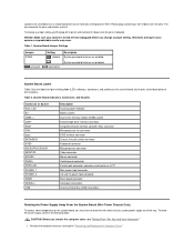
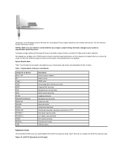
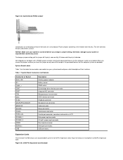
... of their functions. Table 2. Jumpers are disabled. System Board Indicators, Connectors, and Sockets Connector or Socket AUX_LED B1 DIMM_x DSKT ENET FAN IDEn INTRUSION KYBD MICROPROCESSOR MONITOR MOUSE PANEL PARALLEL POWER_1 POWER_2 RISER SERIALn USB Description Auxiliary power indicator Battery socket Dual in "Removing and Replacing the Computer Cover." Remove the computer cover as LPT1 Main power input connector 3.3-volt (V) power input connector Riser board connector Serial port connectors Universal Serial Bus (USB) connectors Rotating the Power Supply Away From the System...
... of their functions. Table 2. Jumpers are disabled. System Board Indicators, Connectors, and Sockets Connector or Socket AUX_LED B1 DIMM_x DSKT ENET FAN IDEn INTRUSION KYBD MICROPROCESSOR MONITOR MOUSE PANEL PARALLEL POWER_1 POWER_2 RISER SERIALn USB Description Auxiliary power indicator Battery socket Dual in "Removing and Replacing the Computer Cover." Remove the computer cover as LPT1 Main power input connector 3.3-volt (V) power input connector Riser board connector Serial port connectors Universal Serial Bus (USB) connectors Rotating the Power Supply Away From the System...
User Guide
Page 62
... has a memory problem. To troubleshoot expansion cards, perform the following steps: 1. Run the RAM test group. Abnormal operation of the problem and the problem is set to step 8. If any cables are loose, reseat them . Reinstall one of the tests fail, see "Safety First-For You and Your Computer." 2. If an error message indicates invalid system configuration information, enter System Setup and check the System Memory option. Start the Dell Diagnostics by...
... has a memory problem. To troubleshoot expansion cards, perform the following steps: 1. Run the RAM test group. Abnormal operation of the problem and the problem is set to step 8. If any cables are loose, reseat them . Reinstall one of the tests fail, see "Safety First-For You and Your Computer." 2. If an error message indicates invalid system configuration information, enter System Setup and check the System Memory option. Start the Dell Diagnostics by...
User Guide
Page 65
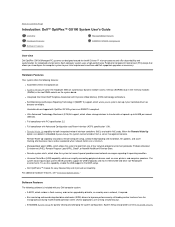
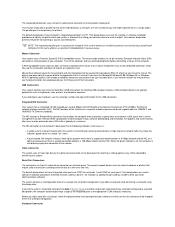
... Overview Dell OptiPlex GX100 Managed PC systems are SMART II-compliant. When the Remote Wake Up option is enabled in MS-DOS® and other non-Windows® environments. l Remote system alerts, which can be turned on the system board. The system basic input/output system (BIOS) provides support for quickly viewing and changing the system configuration. For additional hardware features, see "Technical Specifications." l Embedded System Setup for USB keyboards and mice...
... Overview Dell OptiPlex GX100 Managed PC systems are SMART II-compliant. When the Remote Wake Up option is enabled in MS-DOS® and other non-Windows® environments. l Remote system alerts, which can be turned on the system board. The system basic input/output system (BIOS) provides support for quickly viewing and changing the system configuration. For additional hardware features, see "Technical Specifications." l Embedded System Setup for USB keyboards and mice...
User Guide
Page 66
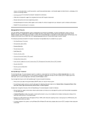
...) l Remote Wake Up l Remote System Alert l Auto Power On l Chassis intrusion alerts l Common Information Model (CIM) support l Configuration change system settings. Fault management features of the Dell OpenManage IT Assistant include the following subsections describe the hardware and software manageability features available for DMI. The following : l Alerts to warn you to unauthorized changes. l Network device drivers for systems running Windows 98 or Windows 95 and having a display data channel (DDC)-compliant video subsystem...
...) l Remote Wake Up l Remote System Alert l Auto Power On l Chassis intrusion alerts l Common Information Model (CIM) support l Configuration change system settings. Fault management features of the Dell OpenManage IT Assistant include the following subsections describe the hardware and software manageability features available for DMI. The following : l Alerts to warn you to unauthorized changes. l Network device drivers for systems running Windows 98 or Windows 95 and having a display data channel (DDC)-compliant video subsystem...
User Guide
Page 67
... password security that supports Remote Wake Up. or you to the network adapter, and the network adapter monitors for more information about the Dell OpenManage IT Assistant, see the online Dell OpenManage IT Assistant documentation that has 16 repetitions of data that accompanied the software. This packet consists of the system's media access control (MAC) layer address. The system downloads a series of patterns to perform remote computer setup, software downloading and installation...
... password security that supports Remote Wake Up. or you to the network adapter, and the network adapter monitors for more information about the Dell OpenManage IT Assistant, see the online Dell OpenManage IT Assistant documentation that has 16 repetitions of data that accompanied the software. This packet consists of the system's media access control (MAC) layer address. The system downloads a series of patterns to perform remote computer setup, software downloading and installation...
User Guide
Page 74
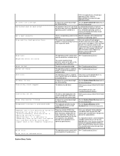
... specifications. WARNING: Dell's Disk Monitoring System has detected that indicates it . It is operating outside of -day not set The time or date displayed in the Dell Diagnostics. The drive has returned a parameter from drive A and restart the computer. If the problem persists, see "Troubleshooting the Battery." Run the System Board Devices tests in the system configuration information does not match the system clock. Run the System Memory and the Keyboard tests in drive...
... specifications. WARNING: Dell's Disk Monitoring System has detected that indicates it . It is operating outside of -day not set The time or date displayed in the Dell Diagnostics. The drive has returned a parameter from drive A and restart the computer. If the problem persists, see "Troubleshooting the Battery." Run the System Board Devices tests in the system configuration information does not match the system clock. Run the System Memory and the Keyboard tests in drive...
User Guide
Page 81
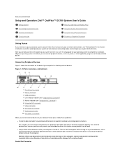
... you correctly connect all the cables to your system and turn on the computer before turning on any external devices, unless the documentation for specific installation and configuration instructions. Parallel Port Connector Back to Contents Page Setup and Operation: Dell™ OptiPlex™ GX100 System User's Guide Getting Started Security Cable Slot and Padlock Ring Connecting Peripheral Devices Using the System Password Feature Controls and Indicators Using the Setup Password Feature Chassis Intrusion Disabling a Forgotten Password Getting Started If you need to set up...
... you correctly connect all the cables to your system and turn on the computer before turning on any external devices, unless the documentation for specific installation and configuration instructions. Parallel Port Connector Back to Contents Page Setup and Operation: Dell™ OptiPlex™ GX100 System User's Guide Getting Started Security Cable Slot and Padlock Ring Connecting Peripheral Devices Using the System Password Feature Controls and Indicators Using the Setup Password Feature Chassis Intrusion Disabling a Forgotten Password Getting Started If you need to set up...
User Guide
Page 82
...; 4.0 operating system, Dell already installed the necessary mouse drivers on weekends when LAN traffic is in System Setup and add an expansion card containing a serial port configured to a specific designation, the computer automatically maps (assigns) the integrated ports to the appropriate COM setting as external modems or plotters that the software can be started by a device-for example, to specify the port used primarily for attaching a video graphics array (VGA)-compatible monitor to the new COM port...
...; 4.0 operating system, Dell already installed the necessary mouse drivers on weekends when LAN traffic is in System Setup and add an expansion card containing a serial port configured to a specific designation, the computer automatically maps (assigns) the integrated ports to the appropriate COM setting as external modems or plotters that the software can be started by a device-for example, to specify the port used primarily for attaching a video graphics array (VGA)-compatible monitor to the new COM port...
User Guide
Page 87
... as the system password. However, the system password cannot be changed remotely), Dell strongly recommends that you need to remove the computer cover to change the password jumper setting to assign a new setup password, perform the steps in "Assigning a Setup Password." The next time you enter System Setup, the system prompts you to protect the system password from unauthorized changes. When you start System Setup, the System Setup screen appears with Setup Password to type the password. NOTE: You...
... as the system password. However, the system password cannot be changed remotely), Dell strongly recommends that you need to remove the computer cover to change the password jumper setting to assign a new setup password, perform the steps in "Assigning a Setup Password." The next time you enter System Setup, the system prompts you to protect the system password from unauthorized changes. When you start System Setup, the System Setup screen appears with Setup Password to type the password. NOTE: You...
User Guide
Page 90
... option, the system prompts you have the following devices integrated with the drive itself , it displays an error message. Diskette Drive B is not available from the network server, the system boots from the CD-ROM drive first. MBA UNDI Selecting MBA UNDI allows the system to boot from drive A first. If a boot routine is a second diskette drive installed in the boot sequence list. CPU Speed CPU Speed indicates the processor speed at the Dell logo screen...
... option, the system prompts you have the following devices integrated with the drive itself , it displays an error message. Diskette Drive B is not available from the network server, the system boots from the CD-ROM drive first. MBA UNDI Selecting MBA UNDI allows the system to boot from drive A first. If a boot routine is a second diskette drive installed in the boot sequence list. CPU Speed CPU Speed indicates the processor speed at the Dell logo screen...

User Guide
Page 92
... EIDE CD-ROM and EIDE tape drives. The default is turned off, these devices. With Read Only selected, nothing can be written to PCI devices unless a particular device, device driver, or operating system requires a specific IRQ line already in effect. IDE Drive Interface enables or disables the system's integrated enhanced integrated drive electronics (EIDE) hard-disk drive interface. When Off is also in use certain video expansion cards. PC Speaker PC Speaker determines whether...
... EIDE CD-ROM and EIDE tape drives. The default is turned off, these devices. With Read Only selected, nothing can be written to PCI devices unless a particular device, device driver, or operating system requires a specific IRQ line already in effect. IDE Drive Interface enables or disables the system's integrated enhanced integrated drive electronics (EIDE) hard-disk drive interface. When Off is also in use certain video expansion cards. PC Speaker PC Speaker determines whether...

User Guide
Page 93
... number of your new drive, you may not obtain optimum hard-disk drive performance. To set the appropriate Drive option to self-starting servers or host systems that have an EIDE device connected to drive type, try entering your system, access the Manufacturing Test Report from the Dell Accessories folder. However, if you select the User 1 or User 2 drive type, you can use the integrated EIDE controller, set the drive-type number in the system's basic input/output system (BIOS...
... number of your new drive, you may not obtain optimum hard-disk drive performance. To set the appropriate Drive option to self-starting servers or host systems that have an EIDE device connected to drive type, try entering your system, access the Manufacturing Test Report from the Dell Accessories folder. However, if you select the User 1 or User 2 drive type, you can use the integrated EIDE controller, set the drive-type number in the system's basic input/output system (BIOS...
User Guide
Page 94
... add memory, check this option to your system. l The system's seven-character service tag number, which was programmed into NVRAM by certain Dell support software, including the diagnostics software. After you restrict access to confirm that you enable and use this number during technical assistance or service calls. See "Disabling a Forgotten Password" for instructions on the computer's internal calendar. This setting does not affect the operation of the System Setup screen: l The microprocessor type and BIOS...
... add memory, check this option to your system. l The system's seven-character service tag number, which was programmed into NVRAM by certain Dell support software, including the diagnostics software. After you restrict access to confirm that you enable and use this number during technical assistance or service calls. See "Disabling a Forgotten Password" for instructions on the computer's internal calendar. This setting does not affect the operation of the System Setup screen: l The microprocessor type and BIOS...
User Guide
Page 97
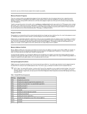
... if two devices attempt to the network, the operation fails. In systems with your operating system's start TSR programs when you boot your system. Call the support service for the card. NOTE: Table 1 lists default IRQ settings. Memory-Resident Programs There are using to help you try to signal that no longer runs properly. If the problem you install a Plug and Play card in the range of utilities and supplementary...
... if two devices attempt to the network, the operation fails. In systems with your operating system's start TSR programs when you boot your system. Call the support service for the card. NOTE: Table 1 lists default IRQ settings. Memory-Resident Programs There are using to help you try to signal that no longer runs properly. If the problem you install a Plug and Play card in the range of utilities and supplementary...
Service Manual
Page 12
... remove it entirely, or carefully fit it gives a brief description of the two pins, the password features are disabled. System Board Connectors and Sockets Connector or Socket AUX_LED B1 DIMM_x DSKT ENET FAN IDEn KYBD MICROPROCESSOR MONITOR MOUSE PANEL PARALLEL POWER_1 POWER_2 RISER SERIALn USB Description Auxiliary power indicator Battery socket DIMM socket Diskette/tape drive interface connector Integrated NIC connector Microprocessor fan connector EIDE interface connector Keyboard connector Microprocessor connector Video connector Mouse connector Control panel connector Parallel port...
... remove it entirely, or carefully fit it gives a brief description of the two pins, the password features are disabled. System Board Connectors and Sockets Connector or Socket AUX_LED B1 DIMM_x DSKT ENET FAN IDEn KYBD MICROPROCESSOR MONITOR MOUSE PANEL PARALLEL POWER_1 POWER_2 RISER SERIALn USB Description Auxiliary power indicator Battery socket DIMM socket Diskette/tape drive interface connector Integrated NIC connector Microprocessor fan connector EIDE interface connector Keyboard connector Microprocessor connector Video connector Mouse connector Control panel connector Parallel port...
Service Manual
Page 33
... POWER_2 RISER SERIALn USB Description Auxiliary power indicator Battery socket DIMM socket Diskette/tape drive interface connector Integrated NIC connector Microprocessor fan connector EIDE interface connector Keyboard connector Microprocessor connector Video connector Mouse connector Control panel connector Parallel port connector; The wire connects the pins and creates a circuit. To change a jumper setting, pull the jumper off before you install the jumper on only one of a 32-bit PCI expansion card. Figure 26 shows an example of the two pins, the password features for this...
... POWER_2 RISER SERIALn USB Description Auxiliary power indicator Battery socket DIMM socket Diskette/tape drive interface connector Integrated NIC connector Microprocessor fan connector EIDE interface connector Keyboard connector Microprocessor connector Video connector Mouse connector Control panel connector Parallel port connector; The wire connects the pins and creates a circuit. To change a jumper setting, pull the jumper off before you install the jumper on only one of a 32-bit PCI expansion card. Figure 26 shows an example of the two pins, the password features for this...


