Setup and Quick Reference Guide
Page 34
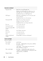
... in sleep state; Connectors (continued) Expansion slots PCI Express Front panel USB Processor Front panel control Front panel audio HDA header Memory Power 12 V Power LAN on motherboard (LOM) Controls and Lights Front of computer: Power button Power light Drive activity light Diagnostic light Mini Tower: four full-height slots Desktop: four half-height... one 10-pin connector one 10-pin connector four 240-pin connectors one 4-pin connector one 24-pin connector through RJ-45 connector on back panel push button blue light -
... in sleep state; Connectors (continued) Expansion slots PCI Express Front panel USB Processor Front panel control Front panel audio HDA header Memory Power 12 V Power LAN on motherboard (LOM) Controls and Lights Front of computer: Power button Power light Drive activity light Diagnostic light Mini Tower: four full-height slots Desktop: four half-height... one 10-pin connector one 10-pin connector four 240-pin connectors one 4-pin connector one 24-pin connector through RJ-45 connector on back panel push button blue light -

Setup and Quick Reference Guide
Page 40
...outlet and press the power button. • If the problem persists, contact Dell (see "Contacting Dell" on properly. • Ensure that the main power cable and front panel cable are securely connected to drain. Plug the computer into an electrical outlet ...and are turned on the back of the computer and the electrical outlet. • Bypass power strips, power extension cables, and other significance. NOTE: The diagnostic...
...outlet and press the power button. • If the problem persists, contact Dell (see "Contacting Dell" on properly. • Ensure that the main power cable and front panel cable are securely connected to drain. Plug the computer into an electrical outlet ...and are turned on the back of the computer and the electrical outlet. • Bypass power strips, power extension cables, and other significance. NOTE: The diagnostic...

Setup and Features Information Tech Sheet
Page 3
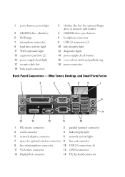
Front and Back View 1 2 3 4 12 11 10 9 13 8 76 5 14 15 16 19 18 17 5 USB 2.0 connectors (2) 7 headphone connector 9 hard drive activity light 11 WiFi (optional) light 13 expansion card slots (4) 15 power supply check light 17 security cable slot 19 back panel connectors 6 microphone connector 8 flex bay (for optional floppy drive, memory card reader, or second 3.5-inch hard disk drive) 10 link integrity light 12 diagnostic lights 14 power supply check button 16 cover release latch and padlock ring 18 power connector Small Form Factor-
Front and Back View 1 2 3 4 12 11 10 9 13 8 76 5 14 15 16 19 18 17 5 USB 2.0 connectors (2) 7 headphone connector 9 hard drive activity light 11 WiFi (optional) light 13 expansion card slots (4) 15 power supply check light 17 security cable slot 19 back panel connectors 6 microphone connector 8 flex bay (for optional floppy drive, memory card reader, or second 3.5-inch hard disk drive) 10 link integrity light 12 diagnostic lights 14 power supply check button 16 cover release latch and padlock ring 18 power connector Small Form Factor-
Setup and Features Information Tech Sheet
Page 4
... drive eject button 6 headphone connector 8 USB 2.0 connectors (2) 10 link integrity light 12 diagnostic lights 14 power supply check button 16 cover release latch and padlock ring 18 power connector Back Panel Connectors - 1 power button, power light 3 CD/DVD drive (slimline) 5 Dell badge 7 microphone connector 9 hard drive activity light 11 WiFi (optional) light 13...
... drive eject button 6 headphone connector 8 USB 2.0 connectors (2) 10 link integrity light 12 diagnostic lights 14 power supply check button 16 cover release latch and padlock ring 18 power connector Back Panel Connectors - 1 power button, power light 3 CD/DVD drive (slimline) 5 Dell badge 7 microphone connector 9 hard drive activity light 11 WiFi (optional) light 13...

Technology Guide
Page 4
DELL™ OPTIPLEX™ 960 TECHNICAL GUIDE MINI TOWER COMPUTER (MT) VIEW FRONT VIEW 1 Hard Drive Activity Light 2 Link Integrity Light 3 Wi-FI Light (optional) 4 Diagnostic Lights 5 Power Button, Power Lights 6 Optical Drive 7 Optical Eject Button Drive 8 Optical Drive Filler Panel Flex Bay (for optional 9 floppy drive or memory card reader) 10 USB 2.0 ...Test Button 2 Power Supply Status Light Cover-release latch 3 and padlock ring (security screw optional) 4 Security Cable Slot 5 Power Cable Connector 6 Back-panel Connectors 7 Expansion-card Slots (4) 4
DELL™ OPTIPLEX™ 960 TECHNICAL GUIDE MINI TOWER COMPUTER (MT) VIEW FRONT VIEW 1 Hard Drive Activity Light 2 Link Integrity Light 3 Wi-FI Light (optional) 4 Diagnostic Lights 5 Power Button, Power Lights 6 Optical Drive 7 Optical Eject Button Drive 8 Optical Drive Filler Panel Flex Bay (for optional 9 floppy drive or memory card reader) 10 USB 2.0 ...Test Button 2 Power Supply Status Light Cover-release latch 3 and padlock ring (security screw optional) 4 Security Cable Slot 5 Power Cable Connector 6 Back-panel Connectors 7 Expansion-card Slots (4) 4

Technology Guide
Page 6
DELL™ OPTIPLEX™ 960 TECHNICAL GUIDE DESKTOP COMPUTER (DT) VIEW FRONT VIEW 1 Power Button, Power Light 2 5.25" Drive Bay 6 Bezel 7 Microphone Connector 3 Headphone Connector 8 3.5" Drive Bay 4 USB 2.0 Connectors (2) 9 Diagnostic Lights 5 Dell Badge BACK VIEW 1 Expansion card slots (4) 2 Power Supply Built in Self Test Button 3 Power Supply Status Light Cover-release Latch 4 and Padlock Ring (security screw optional) 5 Security Cable Slot 6 Power Connector 7 Back-panel Connectors 6
DELL™ OPTIPLEX™ 960 TECHNICAL GUIDE DESKTOP COMPUTER (DT) VIEW FRONT VIEW 1 Power Button, Power Light 2 5.25" Drive Bay 6 Bezel 7 Microphone Connector 3 Headphone Connector 8 3.5" Drive Bay 4 USB 2.0 Connectors (2) 9 Diagnostic Lights 5 Dell Badge BACK VIEW 1 Expansion card slots (4) 2 Power Supply Built in Self Test Button 3 Power Supply Status Light Cover-release Latch 4 and Padlock Ring (security screw optional) 5 Security Cable Slot 6 Power Connector 7 Back-panel Connectors 6
Technology Guide
Page 8
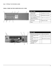
DELL™ OPTIPLEX™ 960 TECHNICAL GUIDE SMALL FORM FACTOR COMPUTER (SFF) VIEW FRONT VIEW 1 Power Button, Power Light 6 Headphone Connector 2 5.25" Drive Bay 7 Microphone Connector 3.5" Flex Bay for Floppy 3 Drive (optional) or 8 USB 2.0 Connectors (2) Media Card (optional) 4 Dell Badge 9 Diagnostic Lights 5 Bezel BACK VIEW 1 Expansion card slots (2) 5 Security Cable Slot 2 Power Supply Check Button 6 Power Cable Connector 3 Power Supply Check Light 7 Back-panel Connectors Cover-release Latch 4 and Padlock Ring (security screw optional) 8
DELL™ OPTIPLEX™ 960 TECHNICAL GUIDE SMALL FORM FACTOR COMPUTER (SFF) VIEW FRONT VIEW 1 Power Button, Power Light 6 Headphone Connector 2 5.25" Drive Bay 7 Microphone Connector 3.5" Flex Bay for Floppy 3 Drive (optional) or 8 USB 2.0 Connectors (2) Media Card (optional) 4 Dell Badge 9 Diagnostic Lights 5 Bezel BACK VIEW 1 Expansion card slots (2) 5 Security Cable Slot 2 Power Supply Check Button 6 Power Cable Connector 3 Power Supply Check Light 7 Back-panel Connectors Cover-release Latch 4 and Padlock Ring (security screw optional) 8


