Setup and Features Information Tech Sheet (Desktop, Mini-Tower, Small Form Factor)
Page 1
About Warnings WARNING: A WARNING indicates a potential for property damage, personal injury, or death. Desktop 1 2 3 4 5 10 98 76 11 12 16 1 optical drive 3 USB 2.0 connectors (2) 5 power button, power light 7 network connectivity light 9 headphone connector March 2010 15 14 13 2 optical drive eject button 4 drive activity light 6 diagnostic lights (4) 8 microphone connector 10 Media Card Reader (optional) Models: DCSM1F, DCNE1F, DCCY1F, DCSM, DCNE, and DCCY series Dell™ OptiPlex™ 780 Setup and Features Information Tech Sheet Front and Back View -
About Warnings WARNING: A WARNING indicates a potential for property damage, personal injury, or death. Desktop 1 2 3 4 5 10 98 76 11 12 16 1 optical drive 3 USB 2.0 connectors (2) 5 power button, power light 7 network connectivity light 9 headphone connector March 2010 15 14 13 2 optical drive eject button 4 drive activity light 6 diagnostic lights (4) 8 microphone connector 10 Media Card Reader (optional) Models: DCSM1F, DCNE1F, DCCY1F, DCSM, DCNE, and DCCY series Dell™ OptiPlex™ 780 Setup and Features Information Tech Sheet Front and Back View -

Setup and Features Information Tech Sheet (Desktop, Mini-Tower, Small Form Factor)
Page 2
... and Back View - Mini-Tower 17 1 2 16 12 11 3 15 4 10 9 5 13 8 6 7 14 1 optical drive 3 optical drive bay (optional) 5 USB 2.0 connectors (2) 7 power button, power light 9 headphone connector 11 network connectivity light 13 back panel connectors 15 cooling vents 17 cover release latch 2 optical drive eject button 4 Media Card Reader (optional) 6 drive activity...
... and Back View - Mini-Tower 17 1 2 16 12 11 3 15 4 10 9 5 13 8 6 7 14 1 optical drive 3 optical drive bay (optional) 5 USB 2.0 connectors (2) 7 power button, power light 9 headphone connector 11 network connectivity light 13 back panel connectors 15 cooling vents 17 cover release latch 2 optical drive eject button 4 Media Card Reader (optional) 6 drive activity...

Setup and Features Information Tech Sheet (Desktop, Mini-Tower, Small Form Factor)
Page 3
Front and Back View - Small Form Factor 1 2 3 4 5 6 10 9 8 7 11 12 15 1 optical drive 3 USB 2.0 connectors (2) 5 diagnostic lights (4) 7 power button, power light 9 headphone connector 11 cover release latch 13 power connector 15 expansion card slots (2) 14 13 2 optical drive eject button 4 network connectivity light 6 drive activity light 8 microphone connector 10 Media Card Reader (optional) 12 padlock ring 14 back panel connectors
Front and Back View - Small Form Factor 1 2 3 4 5 6 10 9 8 7 11 12 15 1 optical drive 3 USB 2.0 connectors (2) 5 diagnostic lights (4) 7 power button, power light 9 headphone connector 11 cover release latch 13 power connector 15 expansion card slots (2) 14 13 2 optical drive eject button 4 network connectivity light 6 drive activity light 8 microphone connector 10 Media Card Reader (optional) 12 padlock ring 14 back panel connectors
Setup and Features Information Tech Sheet (Desktop, Mini-Tower, Small Form Factor)
Page 4
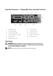
... section, read the safety information that shipped with your computer. For additional best practices information, see www.dell.com/regulatory_compliance. Desktop, Mini-Tower, and Small Form Factor 1 2 3 4 5 6 7 11 10 9 8 1 parallel connector 3 link integrity light 5 network activity light 7 line-in/microphone connector 9 VGA connector 11 DisplayPort connector 2 serial connector 4 network connector 6 line-out connector...
... section, read the safety information that shipped with your computer. For additional best practices information, see www.dell.com/regulatory_compliance. Desktop, Mini-Tower, and Small Form Factor 1 2 3 4 5 6 7 11 10 9 8 1 parallel connector 3 link integrity light 5 network activity light 7 line-in/microphone connector 9 VGA connector 11 DisplayPort connector 2 serial connector 4 network connector 6 line-out connector...
Setup and Features Information Tech Sheet (Desktop, Mini-Tower, Small Form Factor)
Page 8
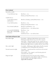
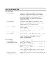
... between the network and the computer. Diagnostic lights Four lights located on the Dell Support website at support.dell.com/manuals. one (slimline drive) Control Lights and Diagnostic Lights Power button light Green light - blinking green light indicates sleep state of the computer. Drive activity light Green light - For more information on the diagnostic lights, see the Service Manual available on the...
... between the network and the computer. Diagnostic lights Four lights located on the Dell Support website at support.dell.com/manuals. one (slimline drive) Control Lights and Diagnostic Lights Power button light Green light - blinking green light indicates sleep state of the computer. Drive activity light Green light - For more information on the diagnostic lights, see the Service Manual available on the...

Setup and Features Information Tech Sheet (Ultra Small Form Factor)
Page 1
Dell™ OptiPlex™ 780 Ultra Small Form Factor Setup and Features Information Tech Sheet Front View 1 2 3 4 5 6 1 CD/DVD drive 3 drive activity light 5 network activity light 7 headphone connector 9 USB connectors (2) 9 8 7 2 power button 4 diagnostic lights (4) 6 WiFi activity light (optional) 8 microphone connector November 2009 Model: D01U Type: D01U001 About Warnings WARNING: A WARNING indicates a potential for property damage, personal injury, or death.
Dell™ OptiPlex™ 780 Ultra Small Form Factor Setup and Features Information Tech Sheet Front View 1 2 3 4 5 6 1 CD/DVD drive 3 drive activity light 5 network activity light 7 headphone connector 9 USB connectors (2) 9 8 7 2 power button 4 diagnostic lights (4) 6 WiFi activity light (optional) 8 microphone connector November 2009 Model: D01U Type: D01U001 About Warnings WARNING: A WARNING indicates a potential for property damage, personal injury, or death.

Setup and Features Information Tech Sheet (Ultra Small Form Factor)
Page 2
Back View 1 2 3 4 5 15 14 13 12 11 10 9 87 6 1 network activity light 3 padlock ring 5 power connector 7 line-in/microphone connector 9 DisplayPort connector 11 serial connector 13 network connector 15 WiFi antenna (optional) 2 captive thumbscrew 4 security cable slot 6 line-out connector 8 eSATA connector 10 VGA connector 12 USB connectors (5) 14 link integrity light
Back View 1 2 3 4 5 15 14 13 12 11 10 9 87 6 1 network activity light 3 padlock ring 5 power connector 7 line-in/microphone connector 9 DisplayPort connector 11 serial connector 13 network connector 15 WiFi antenna (optional) 2 captive thumbscrew 4 security cable slot 6 line-out connector 8 eSATA connector 10 VGA connector 12 USB connectors (5) 14 link integrity light
Setup and Features Information Tech Sheet (Ultra Small Form Factor)
Page 6
... board. Displays the SATA hard drive or CD/DVD drive activity. Blue light - Four amber lights located on the Dell Support website at support.dell.com/manuals. A good 1000 Mbps connection exists between the network and the computer. Yellow light - A blinking yellow light indicates that the computer is reading data from or writing data to the...
... board. Displays the SATA hard drive or CD/DVD drive activity. Blue light - Four amber lights located on the Dell Support website at support.dell.com/manuals. A good 1000 Mbps connection exists between the network and the computer. Yellow light - A blinking yellow light indicates that the computer is reading data from or writing data to the...

Setup and Features Information Tech Sheet (Ultra Small Form Factor)
Page 7
...the top side of the computer) and the electrical outlet. The power cable must be connected during this test. If the LED does not light up, the power supply may be connected to the power connector (at the back of the unit. Voltage 90-264 VAC Frequency 47-...battery 3V CR2032 lithium coin cell Physical Height Width Depth Weight 23.7 cm (9.3 inches) 6.5 cm (2.6 inches) 24.0 cm (9.4 inches) 3.2 kg (7 lbs) Control Lights and Diagnostic Lights (continued) Inside of the power system by using the power supply wattage rating. A test button and LED are not accessible from outside the system...
...the top side of the computer) and the electrical outlet. The power cable must be connected during this test. If the LED does not light up, the power supply may be connected to the power connector (at the back of the unit. Voltage 90-264 VAC Frequency 47-...battery 3V CR2032 lithium coin cell Physical Height Width Depth Weight 23.7 cm (9.3 inches) 6.5 cm (2.6 inches) 24.0 cm (9.4 inches) 3.2 kg (7 lbs) Control Lights and Diagnostic Lights (continued) Inside of the power system by using the power supply wattage rating. A test button and LED are not accessible from outside the system...
Service Manual
Page 6
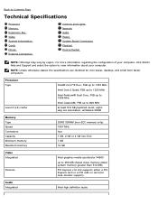
... Discrete Intel graphics media accelerator X4500 up to Contents Page Technical Specifications Processor Memory Expansion Bus Video System Information Cards Drives External Connectors Controls and Lights Network Audio Power System Board Connectors Physical Environmental NOTE: Offerings may vary by region. Processor Type Level 2 (L2) cache Intel® Core™2 Duo; NOTE...
... Discrete Intel graphics media accelerator X4500 up to Contents Page Technical Specifications Processor Memory Expansion Bus Video System Information Cards Drives External Connectors Controls and Lights Network Audio Power System Board Connectors Physical Environmental NOTE: Offerings may vary by region. Processor Type Level 2 (L2) cache Intel® Core™2 Duo; NOTE...
Service Manual
Page 9
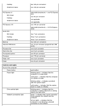
... USB device Processor fan Hard-drive fan Front panel control Processor Power 12V Power Controls and Lights Front of the computer Power button Power light Drive activity light Network connectivity light two 120-pin connectors one 24-pin connector push button blinking green - indicates that the ...- indicates a problem with the system board solid amber - indicates that a good connection exists between the network and the computer off (no light) - indicates that the computer is in sleep state solid green - indicates that the computer is unable to the hard drive green - one...
... USB device Processor fan Hard-drive fan Front panel control Processor Power 12V Power Controls and Lights Front of the computer Power button Power light Drive activity light Network connectivity light two 120-pin connectors one 24-pin connector push button blinking green - indicates that the ...- indicates a problem with the system board solid amber - indicates that a good connection exists between the network and the computer off (no light) - indicates that the computer is in sleep state solid green - indicates that the computer is unable to the hard drive green - one...
Service Manual
Page 10
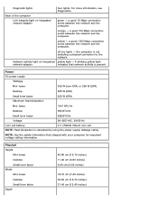
...Heat dissipation is not detecting a physical connection to the network. Diagnostic lights Back of the computer Link integrity light on integrated yellow light - For more information, see Diagnostics. orange - A blinking yellow light network adapter indicates that shipped with your computer for important voltage setting ...information. NOTE: See the safety information that network activity is present. off (no light) - Physical Height Mini-tower Desktop Small form factor Width Mini-tower Desktop Small form factor Depth 40.80 cm ...
...Heat dissipation is not detecting a physical connection to the network. Diagnostic lights Back of the computer Link integrity light on integrated yellow light - For more information, see Diagnostics. orange - A blinking yellow light network adapter indicates that shipped with your computer for important voltage setting ...information. NOTE: See the safety information that network activity is present. off (no light) - Physical Height Mini-tower Desktop Small form factor Width Mini-tower Desktop Small form factor Depth 40.80 cm ...
Service Manual
Page 12
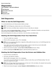
... begin. Then shut down and restart the computer. Back to Contents Page Diagnostics Dell™ OptiPlex™ 780 Service Manual Dell Diagnostics Power Button Light Codes Beep Codes Diagnostic Lights Dell Diagnostics When to run the Dell Diagnostics from the Drivers and Utilities media. NOTE: The Dell Diagnostics software works only on (or restart) your computer's configuration information, and...
... begin. Then shut down and restart the computer. Back to Contents Page Diagnostics Dell™ OptiPlex™ 780 Service Manual Dell Diagnostics Power Button Light Codes Beep Codes Diagnostic Lights Dell Diagnostics When to run the Dell Diagnostics from the Drivers and Utilities media. NOTE: The Dell Diagnostics software works only on (or restart) your computer's configuration information, and...
Service Manual
Page 13
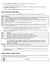
...a description of tracing the problem quickly. Parameters Allows you to your computer. The power light states are also supported in following table for the option you to run . Dell Diagnostics Main Menu 1. This test typically takes 1 hour or more information. Test Symptom ...the version appropriate for the selected device. Power Button Light Codes The diagnostic lights give much more information about the system state, but legacy power light states are shown in your computer. 7. Select Run the 32 Bit Dell Diagnostics from the Drivers and Utilities disc, remove ...
...a description of tracing the problem quickly. Parameters Allows you to your computer. The power light states are also supported in following table for the option you to run . Dell Diagnostics Main Menu 1. This test typically takes 1 hour or more information. Test Symptom ...the version appropriate for the selected device. Power Button Light Codes The diagnostic lights give much more information about the system state, but legacy power light states are shown in your computer. 7. Select Run the 32 Bit Dell Diagnostics from the Drivers and Utilities disc, remove ...

Service Manual
Page 14
... this state to indicate it is probable that can help you identify a faulty component or assembly. If the Hard Drive light is off , light is blank. Look at the diagnostic lights for further information. Beep Codes If the monitor cannot display error messages during the POST. Look at power up . Most beep codes.... Blinking Amber Solid Amber Initial state of beeps that identifies the problem or that an onboard regulator or VRM has failed. If the Hard Drive light on, it has started fetching op-codes. The following table lists the beep codes that may emit a series of...
... this state to indicate it is probable that can help you identify a faulty component or assembly. If the Hard Drive light is off , light is blank. Look at the diagnostic lights for further information. Beep Codes If the monitor cannot display error messages during the POST. Look at power up . Most beep codes.... Blinking Amber Solid Amber Initial state of beeps that identifies the problem or that an onboard regulator or VRM has failed. If the Hard Drive light on, it has started fetching op-codes. The following table lists the beep codes that may emit a series of...
Service Manual
Page 15
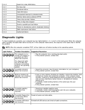
... code to shadowed memory Math-coprocessor test failure Cache test failure Diagnostic Lights To help to identify the problem. If the problem persists, contact Dell. Memory modules are not lit after the computer successfully boots to install... has occurred. If available, install working memory of the lights help troubleshoot a problem, your computer). If the problem persists, contact Dell . A possible USB failure has occurred. 3-4-3 4-2-1 4-2-2 4-2-3 4-2-4 4-3-1 4-3-3 4-3-4 4-4-1 4-4-2 4-4-3 4-4-4 Search for your computer has four lights labeled 1, 2, 3, and 4 on the bank panel....
... code to shadowed memory Math-coprocessor test failure Cache test failure Diagnostic Lights To help to identify the problem. If the problem persists, contact Dell. Memory modules are not lit after the computer successfully boots to install... has occurred. If available, install working memory of the lights help troubleshoot a problem, your computer). If the problem persists, contact Dell . A possible USB failure has occurred. 3-4-3 4-2-1 4-2-2 4-2-3 4-2-4 4-3-1 4-3-3 4-3-4 4-4-1 4-4-2 4-4-3 4-4-4 Search for your computer has four lights labeled 1, 2, 3, and 4 on the bank panel....
Service Manual
Page 17
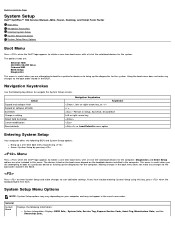
...Use the following keystrokes to change Cancel modification Reset defaults Navigation Keystrokes Keystroke , left- Back to Contents Page System Setup Dell™ OptiPlex™ 780 Service Manual-Mini-Tower, Desktop, and Small Form Factor Boot Menu Navigation Keystrokes Entering System Setup System Setup Simulation System... Options NOTE: System Setup options may vary depending on the bootable devices installed in this key, press when the keyboard lights first flash. The options listed are: Internal HDD CD/DVD/CD-RW Drive Onboard NIC BIOS Setup Diagnostics This menu is...
...Use the following keystrokes to change Cancel modification Reset defaults Navigation Keystrokes Keystroke , left- Back to Contents Page System Setup Dell™ OptiPlex™ 780 Service Manual-Mini-Tower, Desktop, and Small Form Factor Boot Menu Navigation Keystrokes Entering System Setup System Setup Simulation System... Options NOTE: System Setup options may vary depending on the bootable devices installed in this key, press when the keyboard lights first flash. The options listed are: Internal HDD CD/DVD/CD-RW Drive Onboard NIC BIOS Setup Diagnostics This menu is...

Technical Guide
Page 3
DELL™ OPTIPLEX™ 780 TECHNICAL GUIDEBOOK V2.0 MINI TOWER COMPUTER (MT) VIEW FRONT VIEW 1 Optical Drive (optional) 2 Optical Drive Eject Button 3 Optical Drive Bay 7 Power Button, Power Light 8 Diagnostic Lights (4) 9 Headphone Connector BACK VIEW 1 Power Connector 2 Back-Panel ... (optional) 10 Microphone Connector 5 USB 2.0 Connectors (2) 11 Network Connectivity Light 6 Hard Drive Activity Light BACK PANEL CONNECTORS 1 Parallel Connector 7 Line-in Connector 2 Serial Connector 3 Link Integrity Light 8 USB 2.0 Connectors (6) 9 VGA Video Connector 4 Network Connector 10 ...
DELL™ OPTIPLEX™ 780 TECHNICAL GUIDEBOOK V2.0 MINI TOWER COMPUTER (MT) VIEW FRONT VIEW 1 Optical Drive (optional) 2 Optical Drive Eject Button 3 Optical Drive Bay 7 Power Button, Power Light 8 Diagnostic Lights (4) 9 Headphone Connector BACK VIEW 1 Power Connector 2 Back-Panel ... (optional) 10 Microphone Connector 5 USB 2.0 Connectors (2) 11 Network Connectivity Light 6 Hard Drive Activity Light BACK PANEL CONNECTORS 1 Parallel Connector 7 Line-in Connector 2 Serial Connector 3 Link Integrity Light 8 USB 2.0 Connectors (6) 9 VGA Video Connector 4 Network Connector 10 ...
Technical Guide
Page 4
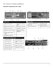
DELL™ OPTIPLEX™ 780 TECHNICAL GUIDEBOOK V2.0 DESKTOP COMPUTER (DT) VIEW FRONT VIEW 1 Optical Drive (optional) 2 Optical Drive Eject Button 7 Network Connectivity Light 8 Microphone Connector 3 USB 2.0 Connectors (2) 9 Headphone Connector 4 Hard Drive Activity Light 10 Media Card Reader (optional) 5 Power Button, Power Light 6 Diagnostic Lights (4) BACK VIEW 1 Expansion Card Slots (3) 2 Air Vent 3 Cover Release Latch 4 Chassis Lock Loop...
DELL™ OPTIPLEX™ 780 TECHNICAL GUIDEBOOK V2.0 DESKTOP COMPUTER (DT) VIEW FRONT VIEW 1 Optical Drive (optional) 2 Optical Drive Eject Button 7 Network Connectivity Light 8 Microphone Connector 3 USB 2.0 Connectors (2) 9 Headphone Connector 4 Hard Drive Activity Light 10 Media Card Reader (optional) 5 Power Button, Power Light 6 Diagnostic Lights (4) BACK VIEW 1 Expansion Card Slots (3) 2 Air Vent 3 Cover Release Latch 4 Chassis Lock Loop...
Technical Guide
Page 5
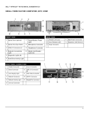
DELL™ OPTIPLEX™ 780 TECHNICAL GUIDEBOOK V2.0 SMALL FORM FACTOR COMPUTER (SFF) VIEW FRONT VIEW 1 Optical Drive (optional) 2 Optical Drive Eject Button 7 Power Button, Power Light 8 Microphone Connector 3 USB 2.0 Connectors (2) 9 Headphone Connector 4 Network Connectivity Light 5 Diagnostic Lights (4) 10 Media Card Reader (optional) 6 Hard Drive Activity Light BACK VIEW 1 Chassis Lock Loop 2 Cover Release Latch 3 Power Connector 4 Back...
DELL™ OPTIPLEX™ 780 TECHNICAL GUIDEBOOK V2.0 SMALL FORM FACTOR COMPUTER (SFF) VIEW FRONT VIEW 1 Optical Drive (optional) 2 Optical Drive Eject Button 7 Power Button, Power Light 8 Microphone Connector 3 USB 2.0 Connectors (2) 9 Headphone Connector 4 Network Connectivity Light 5 Diagnostic Lights (4) 10 Media Card Reader (optional) 6 Hard Drive Activity Light BACK VIEW 1 Chassis Lock Loop 2 Cover Release Latch 3 Power Connector 4 Back...


