Setup and Features Information Tech Sheet (Desktop, Mini-Tower, Small Form Factor)
Page 1
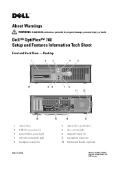
Dell™ OptiPlex™ 780 Setup and Features Information Tech Sheet Front and Back View - Desktop 1 2 3 4 5 10 98 76 11 12 16 1 optical drive 3 USB 2.0 connectors (2) 5 power button, power light 7 network connectivity light 9 headphone connector March 2010 15 14 13 2 optical drive eject button 4 drive activity light 6 diagnostic lights (4) 8 microphone connector 10 Media Card Reader (optional) Models: DCSM1F, DCNE1F, DCCY1F, DCSM, DCNE, and DCCY series About Warnings WARNING: A WARNING indicates a potential for property damage, personal injury, or death.
Dell™ OptiPlex™ 780 Setup and Features Information Tech Sheet Front and Back View - Desktop 1 2 3 4 5 10 98 76 11 12 16 1 optical drive 3 USB 2.0 connectors (2) 5 power button, power light 7 network connectivity light 9 headphone connector March 2010 15 14 13 2 optical drive eject button 4 drive activity light 6 diagnostic lights (4) 8 microphone connector 10 Media Card Reader (optional) Models: DCSM1F, DCNE1F, DCCY1F, DCSM, DCNE, and DCCY series About Warnings WARNING: A WARNING indicates a potential for property damage, personal injury, or death.

Setup and Features Information Tech Sheet (Desktop, Mini-Tower, Small Form Factor)
Page 2
...15 4 10 9 5 13 8 6 7 14 1 optical drive 3 optical drive bay (optional) 5 USB 2.0 connectors (2) 7 power button, power light 9 headphone connector 11 network connectivity light 13 back panel connectors 15 cooling vents 17 cover release latch 2 optical drive eject button 4 Media Card Reader (optional) 6 drive activity light 8 diagnostic lights (4) 10 microphone connector 12 power connector 14 expansion card slots (4) 16 padlock ring 11 cooling vents 13 padlock ring 15 back panel connectors 12 cover release latch 14 power connector 16 expansion card slots (3) Front and Back View -
...15 4 10 9 5 13 8 6 7 14 1 optical drive 3 optical drive bay (optional) 5 USB 2.0 connectors (2) 7 power button, power light 9 headphone connector 11 network connectivity light 13 back panel connectors 15 cooling vents 17 cover release latch 2 optical drive eject button 4 Media Card Reader (optional) 6 drive activity light 8 diagnostic lights (4) 10 microphone connector 12 power connector 14 expansion card slots (4) 16 padlock ring 11 cooling vents 13 padlock ring 15 back panel connectors 12 cover release latch 14 power connector 16 expansion card slots (3) Front and Back View -

Setup and Features Information Tech Sheet (Desktop, Mini-Tower, Small Form Factor)
Page 3
Front and Back View - Small Form Factor 1 2 3 4 5 6 10 9 8 7 11 12 15 1 optical drive 3 USB 2.0 connectors (2) 5 diagnostic lights (4) 7 power button, power light 9 headphone connector 11 cover release latch 13 power connector 15 expansion card slots (2) 14 13 2 optical drive eject button 4 network connectivity light 6 drive activity light 8 microphone connector 10 Media Card Reader (optional) 12 padlock ring 14 back panel connectors
Front and Back View - Small Form Factor 1 2 3 4 5 6 10 9 8 7 11 12 15 1 optical drive 3 USB 2.0 connectors (2) 5 diagnostic lights (4) 7 power button, power light 9 headphone connector 11 cover release latch 13 power connector 15 expansion card slots (2) 14 13 2 optical drive eject button 4 network connectivity light 6 drive activity light 8 microphone connector 10 Media Card Reader (optional) 12 padlock ring 14 back panel connectors
Setup and Features Information Tech Sheet (Desktop, Mini-Tower, Small Form Factor)
Page 8
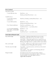
...inch SATA hard drive 19-in-1 Media Card Reader 5.25-inch SATA DVD-ROM, DVD+/-RW, or DVD/CDRW combo drive Mini-Tower - Drives (continued) Internally accessible: 3.5-inch SATA drive bays Available devices: 2.5-inch SATA hard drive (with the system board. one Mini-Tower and Desktop - two Desktop and Small Form Factor - Solid amber light when the computer does not start indicates a problem with the system board or power supply. Off (no light) - one (slimline drive) Control Lights and Diagnostic Lights Power button light Green light - Drive activity light Green light -
...inch SATA hard drive 19-in-1 Media Card Reader 5.25-inch SATA DVD-ROM, DVD+/-RW, or DVD/CDRW combo drive Mini-Tower - Drives (continued) Internally accessible: 3.5-inch SATA drive bays Available devices: 2.5-inch SATA hard drive (with the system board. one Mini-Tower and Desktop - two Desktop and Small Form Factor - Solid amber light when the computer does not start indicates a problem with the system board or power supply. Off (no light) - one (slimline drive) Control Lights and Diagnostic Lights Power button light Green light - Drive activity light Green light -
Setup and Features Information Tech Sheet (Ultra Small Form Factor)
Page 6
... not start indicates a problem with the system board. Yellow light - Solid blue light indicates power-on the Dell Support website at support.dell.com/manuals. Displays the SATA hard drive or CD/DVD drive activity. A good connection exists between the network and the computer. The computer is reading data from or writing data to the drive. For information on the diagnostic lights, see the Service Manual available on state; Blue light - Off (no light) - Four amber lights located...
... not start indicates a problem with the system board. Yellow light - Solid blue light indicates power-on the Dell Support website at support.dell.com/manuals. Displays the SATA hard drive or CD/DVD drive activity. A good connection exists between the network and the computer. The computer is reading data from or writing data to the drive. For information on the diagnostic lights, see the Service Manual available on state; Blue light - Off (no light) - Four amber lights located...

Setup and Features Information Tech Sheet (Ultra Small Form Factor)
Page 7
.... Coin-cell battery 3V CR2032 lithium coin cell Physical Height Width Depth Weight 23.7 cm (9.3 inches) 6.5 cm (2.6 inches) 24.0 cm (9.4 inches) 3.2 kg (7 lbs) Control Lights and Diagnostic Lights (continued) Inside of the power system by using the power supply wattage rating. NOTE: You can test the health of computer: Power supply light Green - NOTE: The test button and indication LED are located under the removable side cover on and is...
.... Coin-cell battery 3V CR2032 lithium coin cell Physical Height Width Depth Weight 23.7 cm (9.3 inches) 6.5 cm (2.6 inches) 24.0 cm (9.4 inches) 3.2 kg (7 lbs) Control Lights and Diagnostic Lights (continued) Inside of the power system by using the power supply wattage rating. NOTE: You can test the health of computer: Power supply light Green - NOTE: The test button and indication LED are located under the removable side cover on and is...

Dell Mounting Bracket - User's Guide (Ultra Small Form Factor)
Page 4
... the System Instruction Guides, packaged separately. 4 of DELL's control, it is imperative that you consult with an appropriate engineering, architectural or construction professional to ensure that your DELL mounting solution can support 50 lbs (23 kg) and is out of 14 About your Dell OptiPlex 780-USFF Mounting ...Bracket Wall Mount 12 3 Under Desk Mount 1 1 2 3 1 System Mounting Bracket 2 System Sleeve 3 System Chassis (ordered separately) Setting up the Dell OptiPlex 780-...
... the System Instruction Guides, packaged separately. 4 of DELL's control, it is imperative that you consult with an appropriate engineering, architectural or construction professional to ensure that your DELL mounting solution can support 50 lbs (23 kg) and is out of 14 About your Dell OptiPlex 780-USFF Mounting ...Bracket Wall Mount 12 3 Under Desk Mount 1 1 2 3 1 System Mounting Bracket 2 System Sleeve 3 System Chassis (ordered separately) Setting up the Dell OptiPlex 780-...
Service Manual
Page 3
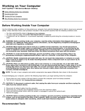
...; Disconnect all attached devices from their electrical outlets. 6. Working on Your Computer Dell™ OptiPlex™ 780 Service Manual-Desktop Before Working Inside Your Computer Recommended Tools Turning Off Your Computer After Working Inside Your Computer Before Working Inside Your Computer Use the following safety guidelines to help protect your computer from potential damage and to help to avoid bending any connector pins. WARNING: Before working inside your computer, ground...
...; Disconnect all attached devices from their electrical outlets. 6. Working on Your Computer Dell™ OptiPlex™ 780 Service Manual-Desktop Before Working Inside Your Computer Recommended Tools Turning Off Your Computer After Working Inside Your Computer Before Working Inside Your Computer Use the following safety guidelines to help protect your computer from potential damage and to help to avoid bending any connector pins. WARNING: Before working inside your computer, ground...

Service Manual
Page 4
... computer turns off . Back to turn off . Turn on your computer. 1. In Windows® XP: Click Start® Turn Off Computer® Turn Off. Connect any replacement procedure, ensure you turn them off your computer. 1. See Dell Diagnostics. After Working Inside Your Computer After you complete any telephone or network cables to their electrical outlets. 4. Replace the cover. CAUTION: To connect a network cable, first plug the cable into the network device and then plug it into...
... computer turns off . Back to turn off . Turn on your computer. 1. In Windows® XP: Click Start® Turn Off Computer® Turn Off. Connect any replacement procedure, ensure you turn them off your computer. 1. See Dell Diagnostics. After Working Inside Your Computer After you complete any telephone or network cables to their electrical outlets. 4. Replace the cover. CAUTION: To connect a network cable, first plug the cable into the network device and then plug it into...
Service Manual
Page 5
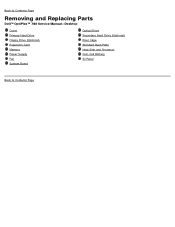
Back to Contents Page Removing and Replacing Parts Dell™ OptiPlex™ 780 Service Manual-Desktop Cover Primary Hard Drive Floppy Drive (Optional) Expansion Card Memory Power Supply Fan System Board Optical Drive Secondary Hard Drive (Optional) Riser Cage Standard Back Plate Heat Sink and Processor Coin-Cell Battery IO Panel Back to Contents Page
Back to Contents Page Removing and Replacing Parts Dell™ OptiPlex™ 780 Service Manual-Desktop Cover Primary Hard Drive Floppy Drive (Optional) Expansion Card Memory Power Supply Fan System Board Optical Drive Secondary Hard Drive (Optional) Riser Cage Standard Back Plate Heat Sink and Processor Coin-Cell Battery IO Panel Back to Contents Page
Service Manual
Page 12
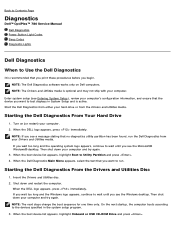
... see Entering System Setup), review your computer's configuration information, and ensure that the device you begin. NOTE: The next steps change the boot sequence for one time only. Back to Contents Page Diagnostics Dell™ OptiPlex™ 780 Service Manual Dell Diagnostics Power Button Light Codes Beep Codes Diagnostic Lights Dell Diagnostics When to Use the Dell Diagnostics It is recommended that you print these procedures before you want to run the Dell Diagnostics from your Drivers and Utilities media. Enter system setup (see the Windows desktop. NOTE...
... see Entering System Setup), review your computer's configuration information, and ensure that the device you begin. NOTE: The next steps change the boot sequence for one time only. Back to Contents Page Diagnostics Dell™ OptiPlex™ 780 Service Manual Dell Diagnostics Power Button Light Codes Beep Codes Diagnostic Lights Dell Diagnostics When to Use the Dell Diagnostics It is recommended that you print these procedures before you want to run the Dell Diagnostics from your Drivers and Utilities media. Enter system setup (see the Windows desktop. NOTE...
Service Manual
Page 13
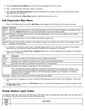
... changing the test settings. 4. Power Button Light Codes The diagnostic lights give much more information. Select the Boot from CD-ROM option from the numbered list. This test typically takes 10 to the Main Menu screen. Help Describes the test and may not display the names of tracing the problem quickly. Configuration Displays your computer. 7. If a problem is encountered during a test, a message appears with an error code and a description of devices. When the tests are running the test. 4. Type 1 to start the menu...
... changing the test settings. 4. Power Button Light Codes The diagnostic lights give much more information. Select the Boot from CD-ROM option from the numbered list. This test typically takes 10 to the Main Menu screen. Help Describes the test and may not display the names of tracing the problem quickly. Configuration Displays your computer. 7. If a problem is encountered during a test, a message appears with an error code and a description of devices. When the tests are running the test. 4. Type 1 to start the menu...
Service Manual
Page 15
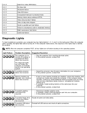
... reinstalled all cable connections. If the computer malfunctions, the sequence of -day clock stopped Serial or parallel port test failure Failure to decompress code to shadowed memory Math-coprocessor test failure Cache test failure Diagnostic Lights To help to the operating system. 3-4-3 4-2-1 4-2-2 4-2-3 4-2-4 4-3-1 4-3-3 4-3-4 4-4-1 4-4-2 4-4-3 4-4-4 Search for your computer has four lights labeled 1, 2, 3, and 4 on the bank panel. When the computer starts normally, the lights flash before turning off before booting to identify the problem. A possible USB failure has...
... reinstalled all cable connections. If the computer malfunctions, the sequence of -day clock stopped Serial or parallel port test failure Failure to decompress code to shadowed memory Math-coprocessor test failure Cache test failure Diagnostic Lights To help to the operating system. 3-4-3 4-2-1 4-2-2 4-2-3 4-2-4 4-3-1 4-3-3 4-3-4 4-4-1 4-4-2 4-4-3 4-4-4 Search for your computer has four lights labeled 1, 2, 3, and 4 on the bank panel. When the computer starts normally, the lights flash before turning off before booting to identify the problem. A possible USB failure has...

Service Manual
Page 16
..., troubleshoot the last card removed from a device (such as the floppy drive or hard drive), check the device to install additional memory modules (one module and restart the computer. No memory modules are detected. A possible expansion card failure has occurred. If the computer starts normally, continue to make sure it is an error message on the screen identifying a problem with a device (such as the floppy drive or optical drive), check system setup to boot...
..., troubleshoot the last card removed from a device (such as the floppy drive or hard drive), check the device to install additional memory modules (one module and restart the computer. No memory modules are detected. A possible expansion card failure has occurred. If the computer starts normally, continue to make sure it is an error message on the screen identifying a problem with a device (such as the floppy drive or optical drive), check system setup to boot...
Service Manual
Page 17
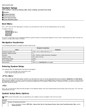
... a one -time boot menu with a list of the valid boot devices for the system. Making changes in Setup, Save/Exit, Discard/Exit Left or right-arrow key or Load Defaults menu option Entering System Setup Your computer offers the following BIOS and System Setup options: Bring up the diagnostics for the computer. The options listed are: Internal HDD CD/DVD/CD-RW Drive Onboard NIC BIOS Setup Diagnostics This menu is useful when you have trouble entering System Setup using this menu. or right...
... a one -time boot menu with a list of the valid boot devices for the system. Making changes in Setup, Save/Exit, Discard/Exit Left or right-arrow key or Load Defaults menu option Entering System Setup Your computer offers the following BIOS and System Setup options: Bring up the diagnostics for the computer. The options listed are: Internal HDD CD/DVD/CD-RW Drive Onboard NIC BIOS Setup Diagnostics This menu is useful when you have trouble entering System Setup using this menu. or right...
Service Manual
Page 18
... RAID mode if enabling Image Server. Internal USB for Flex Bay is configured for legacy mode Legacy mode provides for RAID on a hard drive in this setting: Disable - Identifies and defines the serial port settings. SATA Operation The "USB Controller" Setup option will recognize USB Storage Identifies and defines the parallel port settings. S.M.A.R.T. PXE is incompatible with USB support will affect floppy operation. This field enable and disable the internal USB for Flex bay Disable - You can set : USB for Flex Bay, you are reported during system startup...
... RAID mode if enabling Image Server. Internal USB for Flex Bay is configured for legacy mode Legacy mode provides for RAID on a hard drive in this setting: Disable - Identifies and defines the serial port settings. SATA Operation The "USB Controller" Setup option will recognize USB Storage Identifies and defines the parallel port settings. S.M.A.R.T. PXE is incompatible with USB support will affect floppy operation. This field enable and disable the internal USB for Flex bay Disable - You can set : USB for Flex Bay, you are reported during system startup...

Service Manual
Page 19
... the serial port settings. Enables or disables the following onboard devices: Front USB Rear Dual USB Rear Quad USB PCI slots Audio Video Primary Video This field determines which video controller will improve with the System Password option. Auto(default) - Performance Multi Core Support This field specifies whether the processor will support. Enable Intel® Virtualization Technology - Security Administrative Password System Password Password Changes TPM Security Provides restricted access to use these for Direct I /O. This option is installed. Onboard/Card - Use the...
... the serial port settings. Enables or disables the following onboard devices: Front USB Rear Dual USB Rear Quad USB PCI slots Audio Video Primary Video This field determines which video controller will improve with the System Password option. Auto(default) - Performance Multi Core Support This field specifies whether the processor will support. Enable Intel® Virtualization Technology - Security Administrative Password System Password Password Changes TPM Security Provides restricted access to use these for Direct I /O. This option is installed. Onboard/Card - Use the...

Service Manual
Page 20
... set. Change the startup time by default. This option is set to your system board. NOTE: The system setup program displays a password for the hard drive connected to the SATA-0 connector on a power strip or surge protector or if Auto Power On is disabled by typing the values in the system setup. Fan Control Override Controls the speed of the hard drives connected to disabled. Allows you turn on the computer. This option is kept in Hibernate mode. You can set this option...
... set. Change the startup time by default. This option is set to your system board. NOTE: The system setup program displays a password for the hard drive connected to the SATA-0 connector on a power strip or surge protector or if Auto Power On is disabled by typing the values in the system setup. Fan Control Override Controls the speed of the hard drives connected to disabled. Allows you turn on the computer. This option is kept in Hibernate mode. You can set this option...

Service Manual
Page 21
... must set the Integrated NIC to Enable with ImageServer to Static IP Displays the current license status. Static IP DHCP (default) Specifies the static IP address of each key. NumLock LED Enables or disables the NumLock feature when your computer starts more then 2GB of the image server with more quickly because it skips certain configurations and tests. When enabled (default), this option activates the cursor-control...
... must set the Integrated NIC to Enable with ImageServer to Static IP Displays the current license status. Static IP DHCP (default) Specifies the static IP address of each key. NumLock LED Enables or disables the NumLock feature when your computer starts more then 2GB of the image server with more quickly because it skips certain configurations and tests. When enabled (default), this option activates the cursor-control...
Service Manual
Page 36
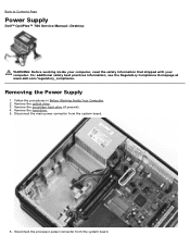
... power connector from the system board. Disconnect the processor power connector from the system board. 6. Removing the Power Supply 1. Remove the optical drive. 3. Back to Contents Page Power Supply Dell™ OptiPlex™ 780 Service Manual-Desktop WARNING: Before working inside your computer, read the safety information that shipped with your computer. For additional safety best practices information, see the Regulatory Compliance Homepage at www.dell.com/regulatory_compliance. Remove the hard drive. 5. Follow the procedures in Before Working Inside...
... power connector from the system board. Disconnect the processor power connector from the system board. 6. Removing the Power Supply 1. Remove the optical drive. 3. Back to Contents Page Power Supply Dell™ OptiPlex™ 780 Service Manual-Desktop WARNING: Before working inside your computer, read the safety information that shipped with your computer. For additional safety best practices information, see the Regulatory Compliance Homepage at www.dell.com/regulatory_compliance. Remove the hard drive. 5. Follow the procedures in Before Working Inside...


