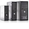
Setup and Features Information Tech Sheet (Desktop, Mini-Tower, Small Form Factor)
Page 8
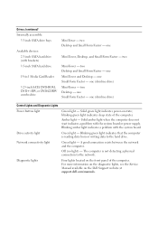
... is not detecting a physical connection to the hard drive. one Small Form Factor - The computer is reading data from or writing data to the network. one (slimline drive) Control Lights and Diagnostic Lights Power button light...dell.com/manuals. one (slimline drive) Mini-Tower - one Mini-Tower and Desktop - Diagnostic lights Four lights located on the front panel of the computer. two Desktop and Small Form Factor - Drives (continued) Internally accessible: 3.5-inch SATA drive bays Available devices: 2.5-inch SATA hard drive (with brackets) 3.5-inch SATA hard drive...
... is not detecting a physical connection to the hard drive. one Small Form Factor - The computer is reading data from or writing data to the network. one (slimline drive) Control Lights and Diagnostic Lights Power button light...dell.com/manuals. one (slimline drive) Mini-Tower - one Mini-Tower and Desktop - Diagnostic lights Four lights located on the front panel of the computer. two Desktop and Small Form Factor - Drives (continued) Internally accessible: 3.5-inch SATA drive bays Available devices: 2.5-inch SATA hard drive (with brackets) 3.5-inch SATA hard drive...
Setup and Features Information Tech Sheet (Ultra Small Form Factor)
Page 5
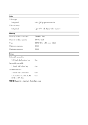
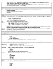
Video Video type: Integrated Video memory: Integrated Intel Q45 graphics controller Upto 1759 MB shared video memory Memory Memory module connector Memory module capacity Type Minimum memory Maximum memory 2 DIMM slots 1 GB or 2 GB DDR3 1066 MHz (non-ECC) 1 GB 4 GB Drives Externally accessible: 5.25-inch slimline drive bay One Internally accessible: 2.5-inch SATA drive bay One Available devices: 2.5-inch SATA hard drive One 5.25-inch SATA DVD-ROM, One DVD+/-RW drive NOTE: Supports a maximum of one hard drive.
Video Video type: Integrated Video memory: Integrated Intel Q45 graphics controller Upto 1759 MB shared video memory Memory Memory module connector Memory module capacity Type Minimum memory Maximum memory 2 DIMM slots 1 GB or 2 GB DDR3 1066 MHz (non-ECC) 1 GB 4 GB Drives Externally accessible: 5.25-inch slimline drive bay One Internally accessible: 2.5-inch SATA drive bay One Available devices: 2.5-inch SATA hard drive One 5.25-inch SATA DVD-ROM, One DVD+/-RW drive NOTE: Supports a maximum of one hard drive.
Setup and Features Information Tech Sheet (Ultra Small Form Factor)
Page 6
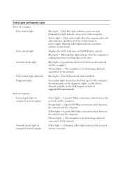
Solid blue light indicates power-on the Dell Support website at support.dell.com/manuals. Amber light - Blue light - The computer...and the computer. Yellow light - Control Lights and Diagnostic Lights Front of computer: Power button light Drive activity light Network activity light WiFi activity light (optional) Diagnostic lights Back of the computer. blinking blue... supply. Four amber lights located on integrated network adapter Blue light - Displays the SATA hard drive or CD/DVD drive activity. Blue light - The computer is reading data from or writing data to the network...
Solid blue light indicates power-on the Dell Support website at support.dell.com/manuals. Amber light - Blue light - The computer...and the computer. Yellow light - Control Lights and Diagnostic Lights Front of computer: Power button light Drive activity light Network activity light WiFi activity light (optional) Diagnostic lights Back of the computer. blinking blue... supply. Four amber lights located on integrated network adapter Blue light - Displays the SATA hard drive or CD/DVD drive activity. Blue light - The computer is reading data from or writing data to the network...
Service Manual
Page 5
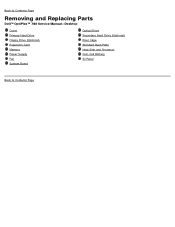
Back to Contents Page Removing and Replacing Parts Dell™ OptiPlex™ 780 Service Manual-Desktop Cover Primary Hard Drive Floppy Drive (Optional) Expansion Card Memory Power Supply Fan System Board Optical Drive Secondary Hard Drive (Optional) Riser Cage Standard Back Plate Heat Sink and Processor Coin-Cell Battery IO Panel Back to Contents Page
Back to Contents Page Removing and Replacing Parts Dell™ OptiPlex™ 780 Service Manual-Desktop Cover Primary Hard Drive Floppy Drive (Optional) Expansion Card Memory Power Supply Fan System Board Optical Drive Secondary Hard Drive (Optional) Riser Cage Standard Back Plate Heat Sink and Processor Coin-Cell Battery IO Panel Back to Contents Page
Service Manual
Page 8
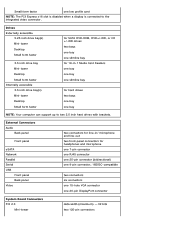
... Connectors PCI 2.3 Mini-tower data width (maximum) - 32 bits two 120-pin connectors Drives Externally accessible 5.25 inch drive bay(s) Mini-tower Desktop Small form factor 3.5 inch drive bay Mini-tower Desktop Small form factor Internally accessible 3.5 inch drive bay(s) Mini-tower Desktop Small form factor for SATA DVD-ROM, DVD+/-RW, or... bays one bay one slimline bay for 19-in / microphone and line-out two front-panel connectors for hard drives two bays one bay one bay NOTE: Your computer can support up to the integrated video connector. Small form factor one low profile card NOTE:...
... Connectors PCI 2.3 Mini-tower data width (maximum) - 32 bits two 120-pin connectors Drives Externally accessible 5.25 inch drive bay(s) Mini-tower Desktop Small form factor 3.5 inch drive bay Mini-tower Desktop Small form factor Internally accessible 3.5 inch drive bay(s) Mini-tower Desktop Small form factor for SATA DVD-ROM, DVD+/-RW, or... bays one bay one slimline bay for 19-in / microphone and line-out two front-panel connectors for hard drives two bays one bay one bay NOTE: Your computer can support up to the integrated video connector. Small form factor one low profile card NOTE:...
Service Manual
Page 9
... power-on state blinking amber - indicates a problem with the system board solid amber - indicates that the computer is unable to the hard drive green - Desktop Small form factor PCI Express x1 Mini-tower Desktop Small form factor PCI Express x16 Serial ATA Mini-tower Desktop Small ...form factor Memory Internal USB device Processor fan Hard-drive fan Front panel control Processor Power 12V Power Controls and Lights Front of the computer Power button Power light Drive activity light Network connectivity light two 120-pin connectors one 24-pin connector...
... power-on state blinking amber - indicates a problem with the system board solid amber - indicates that the computer is unable to the hard drive green - Desktop Small form factor PCI Express x1 Mini-tower Desktop Small form factor PCI Express x16 Serial ATA Mini-tower Desktop Small ...form factor Memory Internal USB device Processor fan Hard-drive fan Front panel control Processor Power 12V Power Controls and Lights Front of the computer Power button Power light Drive activity light Network connectivity light two 120-pin connectors one 24-pin connector...
Service Manual
Page 12
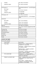
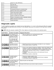
...Dell™ OptiPlex™ 780 Service Manual Dell Diagnostics Power Button Light Codes Beep Codes Diagnostic Lights Dell Diagnostics When to Use the Dell Diagnostics It is optional and may not ship with your computer. When the DELL logo appears, press immediately. Insert the Drivers and Utilities disc. 2. Turn on Dell... press . 4. NOTE: The next steps change the boot sequence for one time only. Start the Dell Diagnostics from either your hard drive or from your computer's configuration information, and ensure that the device you see a message stating that ...
...Dell™ OptiPlex™ 780 Service Manual Dell Diagnostics Power Button Light Codes Beep Codes Diagnostic Lights Dell Diagnostics When to Use the Dell Diagnostics It is optional and may not ship with your computer. When the DELL logo appears, press immediately. Insert the Drivers and Utilities disc. 2. Turn on Dell... press . 4. NOTE: The next steps change the boot sequence for one time only. Start the Dell Diagnostics from either your hard drive or from your computer's configuration information, and ensure that the device you see a message stating that ...

Service Manual
Page 14
... System is in a low power state, either S1 or S3. Look at the diagnostic lights to indicate it has started fetching op-codes. If the Hard Drive light on, it is probable that the power supply needs to be generated during the POST, the computer may be replaced. Indicates the POWER_GOOD signal...
... System is in a low power state, either S1 or S3. Look at the diagnostic lights to indicate it has started fetching op-codes. If the Hard Drive light on, it is probable that the power supply needs to be generated during the POST, the computer may be replaced. Indicates the POWER_GOOD signal...
Service Manual
Page 15
... A20 failure Unexpected interrupt in a normal off . A possible floppy drive or hard drive failure has occurred. NOTE: After the computer completes POST, all modules without error. If the problem persists, contact Dell. A possible processor failure has occurred. If the computer starts normally,...of the lights help troubleshoot a problem, your computer. A possible graphics card failure has occurred. If the problem persists, contact Dell . Reseat all cable connections. If the computer malfunctions, the sequence of -day clock stopped Serial or parallel port test failure...
... A20 failure Unexpected interrupt in a normal off . A possible floppy drive or hard drive failure has occurred. NOTE: After the computer completes POST, all modules without error. If the problem persists, contact Dell. A possible processor failure has occurred. If the computer starts normally,...of the lights help troubleshoot a problem, your computer. A possible graphics card failure has occurred. If the problem persists, contact Dell . Reseat all cable connections. If the computer malfunctions, the sequence of -day clock stopped Serial or parallel port test failure...

Service Manual
Page 16
... computer. If the problem persists, contact Dell. If the problem persists, contact Dell. Another failure has occurred. If the problem persists, contact Dell. A possible expansion card failure has occurred. If the problem persists, reinstall the card you have identified a faulty module or reinstalled all hard drive and optical drive cables are using is correct for the...
... computer. If the problem persists, contact Dell. If the problem persists, contact Dell. Another failure has occurred. If the problem persists, contact Dell. A possible expansion card failure has occurred. If the problem persists, reinstall the card you have identified a faulty module or reinstalled all hard drive and optical drive cables are using is correct for the...
Service Manual
Page 18
... serial port to : Disable Enable (default) Enable with PXE Enable with ImageSever ImageServe is incompatible with USB support will recognize USB Floppy drives regardless of the integrated hard drive controller. Onboard or USB Floppy HDD(will show the model currently in system) Onboard or USB CD-Rom...part of the integrated parallel port. PXE is needed only if intending to boost to an operating system located on every boot Legacy = The hard drive controller is configured for legacy mode Legacy mode provides for Flex Bay is configured for RAID on a server, not if you can set the...
... serial port to : Disable Enable (default) Enable with PXE Enable with ImageSever ImageServe is incompatible with USB support will recognize USB Floppy drives regardless of the integrated hard drive controller. Onboard or USB Floppy HDD(will show the model currently in system) Onboard or USB CD-Rom...part of the integrated parallel port. PXE is needed only if intending to boost to an operating system located on every boot Legacy = The hard drive controller is configured for legacy mode Legacy mode provides for Flex Bay is configured for RAID on a server, not if you can set the...

Service Manual
Page 19
...Some operating systems will improve with the System Password option. HDD Acoustic Mode This option is slower, but possibly noisier. The drive is disabled by default. Enables or disables the user from utilizing the additional hardware capabilities provided by Intel® Virtualization technology...Intel® SpeedStep™ mode of the system's password security feature and allows a new system password to optimize your hard drives performance and acoustic noise level based on your personal preferences. Identifies and defines the serial port settings. A PCI Express ...
...Some operating systems will improve with the System Password option. HDD Acoustic Mode This option is slower, but possibly noisier. The drive is disabled by default. Enables or disables the user from utilizing the additional hardware capabilities provided by Intel® Virtualization technology...Intel® SpeedStep™ mode of the system's password security feature and allows a new system password to optimize your hard drives performance and acoustic noise level based on your personal preferences. Identifies and defines the serial port settings. A PCI Express ...

Service Manual
Page 20
... how the system responds when AC power is set to : Deactivate (default) Disable Activate SATA-0 Password Displays the current status of the hard drives connected to the SATA-0 connector on the computer. Static IP DNS NOTE: You must set the Integrated NIC to Enable with which the ...ImageServer looks for each of the password set this option to disabled. Enables or disables the optional Computrace® service designed for the hard drive connected to your system board. Enables or disables the execute disable mode of the system fan. When low power mode is enabled, the...
... how the system responds when AC power is set to : Deactivate (default) Disable Activate SATA-0 Password Displays the current status of the hard drives connected to the SATA-0 connector on the computer. Static IP DNS NOTE: You must set the Integrated NIC to Enable with which the ...ImageServer looks for each of the password set this option to disabled. Enables or disables the optional Computrace® service designed for the hard drive connected to your system board. Enables or disables the execute disable mode of the system fan. When low power mode is enabled, the...
Service Manual
Page 24
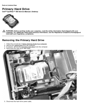
If present, remove the secondary hard drive from the computer. 3. Remove the optical drive from the computer. 4. Disconnect the hard-drive power cable. For additional safety best practices information, see the Regulatory Compliance Homepage at www.dell.com/regulatory_compliance. Removing the Primary Hard Drive 1. Disconnect the hard-drive data cable. 5. Back to Contents Page Primary Hard Drive Dell™ OptiPlex™ 780 Service Manual-Desktop WARNING...
If present, remove the secondary hard drive from the computer. 3. Remove the optical drive from the computer. 4. Disconnect the hard-drive power cable. For additional safety best practices information, see the Regulatory Compliance Homepage at www.dell.com/regulatory_compliance. Removing the Primary Hard Drive 1. Disconnect the hard-drive data cable. 5. Back to Contents Page Primary Hard Drive Dell™ OptiPlex™ 780 Service Manual-Desktop WARNING...

Service Manual
Page 26
Lift the hard drive and remove it from the system. 7.
Lift the hard drive and remove it from the system. 7.

Service Manual
Page 27
Back to Contents Page Replacing the Primary Hard Drive To replace the hard drive, perform the above steps in reverse order.
Back to Contents Page Replacing the Primary Hard Drive To replace the hard drive, perform the above steps in reverse order.
Service Manual
Page 36
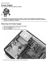
.../regulatory_compliance. Disconnect the processor power connector from the system board. 6. Remove the hard drive. 5. Remove the secondary hard drive (if present). 4. Disconnect the main power connector from the system board. Back to Contents Page Power Supply Dell™ OptiPlex™ 780 Service Manual-Desktop WARNING: Before working inside your computer, read the safety information that shipped with...
.../regulatory_compliance. Disconnect the processor power connector from the system board. 6. Remove the hard drive. 5. Remove the secondary hard drive (if present). 4. Disconnect the main power connector from the system board. Back to Contents Page Power Supply Dell™ OptiPlex™ 780 Service Manual-Desktop WARNING: Before working inside your computer, read the safety information that shipped with...
Service Manual
Page 49
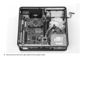
Disconnect the hard-drive data cable from the system board. 10.
Disconnect the hard-drive data cable from the system board. 10.
Service Manual
Page 59
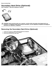
Follow the procedures in Before Working Inside Your Computer. 2. Disconnect the hard-drive data cable. Removing the Secondary Hard Drive (Optional) 1. Remove the optical drive from the computer. 3. For additional safety best practices information, see the Regulatory Compliance Homepage at www.dell.com/regulatory_compliance. Back to Contents Page Secondary Hard Drive (Optional) Dell™ OptiPlex™ 780 Service Manual-Desktop WARNING: Before working inside your computer, read the safety information that shipped with your computer.
Follow the procedures in Before Working Inside Your Computer. 2. Disconnect the hard-drive data cable. Removing the Secondary Hard Drive (Optional) 1. Remove the optical drive from the computer. 3. For additional safety best practices information, see the Regulatory Compliance Homepage at www.dell.com/regulatory_compliance. Back to Contents Page Secondary Hard Drive (Optional) Dell™ OptiPlex™ 780 Service Manual-Desktop WARNING: Before working inside your computer, read the safety information that shipped with your computer.
Service Manual
Page 60
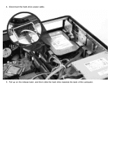
4. Pull up on the release latch, and then slide the hard drive towards the back of the computer. Disconnect the hard-drive power cable. 5.
4. Pull up on the release latch, and then slide the hard drive towards the back of the computer. Disconnect the hard-drive power cable. 5.


