
Setup and Quick Reference Guide
Page 7
Front View 1 2 3 4 5 11 10 98 76 1 optical drive 3 USB 2.0 connectors (2) 5 power button, power light 7 network-connectivity light 9 headphone connector 11 floppy drive or Media Card Reader (optional) 2 optical-drive eject button 4 hard-drive activity light 6 diagnostic lights (4) 8 microphone connector 10 optional floppy drive eject button About Your Computer 7 About Your Computer Desktop -
Front View 1 2 3 4 5 11 10 98 76 1 optical drive 3 USB 2.0 connectors (2) 5 power button, power light 7 network-connectivity light 9 headphone connector 11 floppy drive or Media Card Reader (optional) 2 optical-drive eject button 4 hard-drive activity light 6 diagnostic lights (4) 8 microphone connector 10 optional floppy drive eject button About Your Computer 7 About Your Computer Desktop -
Setup and Quick Reference Guide
Page 10
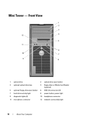
Mini Tower - Front View 1 2 3 4 12 5 11 6 10 7 9 8 1 optical drive 3 optional optical drive bay 5 optional floppy drive eject button 7 hard-drive activity light 9 diagnostic lights (4) 11 microphone connector 2 optical-drive eject button 4 floppy drive or Media Card Reader (optional) 6 USB 2.0 connectors (2) 8 power button, power light 10 headphone connector 12 network-connectivity light 10 About Your Computer
Mini Tower - Front View 1 2 3 4 12 5 11 6 10 7 9 8 1 optical drive 3 optional optical drive bay 5 optional floppy drive eject button 7 hard-drive activity light 9 diagnostic lights (4) 11 microphone connector 2 optical-drive eject button 4 floppy drive or Media Card Reader (optional) 6 USB 2.0 connectors (2) 8 power button, power light 10 headphone connector 12 network-connectivity light 10 About Your Computer

Setup and Quick Reference Guide
Page 13
Small Form Factor - Front View 1 2 3 4 5 6 11 10 9 8 7 1 optical drive 2 optical-drive eject button 3 USB 2.0 connectors (2) 4 network-connectivity light 5 diagnostic lights (4) 6 hard-drive activity light 7 power button, power light 8 microphone connector 9 headphone connector 10 optional floppy drive eject button 11 floppy drive or Media Card Reader (optional) About Your Computer 13
Small Form Factor - Front View 1 2 3 4 5 6 11 10 9 8 7 1 optical drive 2 optical-drive eject button 3 USB 2.0 connectors (2) 4 network-connectivity light 5 diagnostic lights (4) 6 hard-drive activity light 7 power button, power light 8 microphone connector 9 headphone connector 10 optional floppy drive eject button 11 floppy drive or Media Card Reader (optional) About Your Computer 13

Setup and Quick Reference Guide
Page 14
Small Form Factor - Back Panel Connectors 1 2 3 4 5 6 7 11 10 1 parallel connector 3 link-integrity light 5 network-activity light 7 line-in connector 9 VGA video connector 11 DisplayPort connector 14 About Your Computer 9 8 2 serial connector 4 network connector 6 line-out connector 8 USB 2.0 connectors (6) 10 eSATA connector Back View 1 2 5 4 3 1 padlock rings 3 power connector 5 expansion-card slots (2) 2 cover release latch 4 back-panel connectors Small Form Factor -
Small Form Factor - Back Panel Connectors 1 2 3 4 5 6 7 11 10 1 parallel connector 3 link-integrity light 5 network-activity light 7 line-in connector 9 VGA video connector 11 DisplayPort connector 14 About Your Computer 9 8 2 serial connector 4 network connector 6 line-out connector 8 USB 2.0 connectors (6) 10 eSATA connector Back View 1 2 5 4 3 1 padlock rings 3 power connector 5 expansion-card slots (2) 2 cover release latch 4 back-panel connectors Small Form Factor -

Setup and Quick Reference Guide
Page 15
Front View 1 2 34 98 1 USB 2.0 connectors (2) 3 hard drive activity light 5 air vents 7 optical drive 9 air vents 76 5 2 microphone connector 4 power button, power light 6 optical-drive eject button 8 headphone connector Ultra Small Form Factor - Ultra Small Form Factor - Back View 1 2 3 6 1 diagnostic lights (4) 3 security cable slot 5 power connector 5 4 2 cover release knob 4 back-panel connectors 6 air vent About Your Computer 15
Front View 1 2 34 98 1 USB 2.0 connectors (2) 3 hard drive activity light 5 air vents 7 optical drive 9 air vents 76 5 2 microphone connector 4 power button, power light 6 optical-drive eject button 8 headphone connector Ultra Small Form Factor - Ultra Small Form Factor - Back View 1 2 3 6 1 diagnostic lights (4) 3 security cable slot 5 power connector 5 4 2 cover release knob 4 back-panel connectors 6 air vent About Your Computer 15

Setup and Quick Reference Guide
Page 24
The computer will not operate in this condition. The AC power adapter has a status light that the power adapter is connected to an AC power outlet and to the power outlet. 24 ...Setting Up Your Computer solid amber indicates that the power adapter is green or amber for the following different states: • green light - 1 2 1 grounding source (screw) 2 metal ground connector 4 Connect the AC power cable to the computer. solid green indicates that ...computer and/or reset the power adapter by disconnecting and reconnecting the plug to the computer. • amber light -
The computer will not operate in this condition. The AC power adapter has a status light that the power adapter is connected to an AC power outlet and to the power outlet. 24 ...Setting Up Your Computer solid amber indicates that the power adapter is green or amber for the following different states: • green light - 1 2 1 grounding source (screw) 2 metal ground connector 4 Connect the AC power cable to the computer. solid green indicates that ...computer and/or reset the power adapter by disconnecting and reconnecting the plug to the computer. • amber light -

Setup and Quick Reference Guide
Page 41
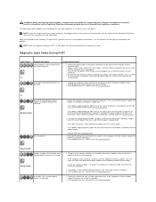
... indicates a problem with the system board. A good connection exists between the network and the computer. Drive activity light green light - A blinking green light indicates that the system board cannot start indicates that the computer is not detecting a physical connection to the SATA ...pin connector one 775-pin connector one 4-pin connector one 24-pin connector Controls and Lights Front of computer: Power button push button Power light green light - solid green for power-on page 46). amber light - This could be a system board or a power supply problem (see "Power ...
... indicates a problem with the system board. A good connection exists between the network and the computer. Drive activity light green light - A blinking green light indicates that the system board cannot start indicates that the computer is not detecting a physical connection to the SATA ...pin connector one 775-pin connector one 4-pin connector one 24-pin connector Controls and Lights Front of computer: Power button push button Power light green light - solid green for power-on page 46). amber light - This could be a system board or a power supply problem (see "Power ...
Setup and Quick Reference Guide
Page 42
... is not detecting a physical connection to the network. Back of the computer: Link integrity light on the back panel. Controls and Lights (continued) Diagnostic lights four lights NOTE: For the ultra small form factor computer, the diagnostic lights are on green light - A good 10 Mbps connection exists integrated network adapter between the network and the computer...
... is not detecting a physical connection to the network. Back of the computer: Link integrity light on the back panel. Controls and Lights (continued) Diagnostic lights four lights NOTE: For the ultra small form factor computer, the diagnostic lights are on green light - A good 10 Mbps connection exists integrated network adapter between the network and the computer...

Setup and Quick Reference Guide
Page 46
... device, such as a lamp. • Ensure that shipped with your Service Manual at www.dell.com/regulatory_compliance. I F T H E P O W E R L I G H T I S B L I N K I N G G R E E N - IF T H E POWER LIGHT IS O F F - IF THE POWER LIGHT IS GREEN AND THE COMPUTER IS NOT RESPONDING - • Ensure that the part is correctly installed...computer. Press a key on . • If the display is in a program, see the Regulatory Compliance Homepage at support.dell.com). Power Problems CAUTION: Before you added or removed a part before the problem started, review the installation procedures and ensure...
... device, such as a lamp. • Ensure that shipped with your Service Manual at www.dell.com/regulatory_compliance. I F T H E P O W E R L I G H T I S B L I N K I N G G R E E N - IF T H E POWER LIGHT IS O F F - IF THE POWER LIGHT IS GREEN AND THE COMPUTER IS NOT RESPONDING - • Ensure that the part is correctly installed...computer. Press a key on . • If the display is in a program, see the Regulatory Compliance Homepage at support.dell.com). Power Problems CAUTION: Before you added or removed a part before the problem started, review the installation procedures and ensure...

Setup and Quick Reference Guide
Page 74
... setting up, 28 L license label, 64 P phone numbers, 71 power power light conditions, 46 troubleshooting, 46 problems restore to previous state, 57 M media Drivers and Utilities, 63 operating system, 63 memory troubleshooting, 47 N networks, 23 connecting, 23 O operating system Dell Factory Image Restore, 58 media, 60 reinstalling, 63 System Restore, 56 Operating...
... setting up, 28 L license label, 64 P phone numbers, 71 power power light conditions, 46 troubleshooting, 46 problems restore to previous state, 57 M media Drivers and Utilities, 63 operating system, 63 memory troubleshooting, 47 N networks, 23 connecting, 23 O operating system Dell Factory Image Restore, 58 media, 60 reinstalling, 63 System Restore, 56 Operating...
Setup and Quick Reference Guide
Page 75
specifications all, 35 audio, 36 connectors, 39 controls and lights, 41 drives, 37 environmental, 44 expansion bus, 36 memory, 35 physical, 43 power, 42 processor, 35 system information, 35 video, 36 support, 65 contacting Dell, 71 DellConnect, 66 online services, 66 regional, 66 technical ...Conditions, 64 transferring information to a new computer, 30 troubleshooting, 45, 64 blue screen, 49 computer not responding, 48 Dell Diagnostics, 50 memory, 47 power, 46 power light conditions, 46 program crashes, 48 programs and Windows compatibility, 48 restore to previous state, 56-57 software, 48-49...
specifications all, 35 audio, 36 connectors, 39 controls and lights, 41 drives, 37 environmental, 44 expansion bus, 36 memory, 35 physical, 43 power, 42 processor, 35 system information, 35 video, 36 support, 65 contacting Dell, 71 DellConnect, 66 online services, 66 regional, 66 technical ...Conditions, 64 transferring information to a new computer, 30 troubleshooting, 45, 64 blue screen, 49 computer not responding, 48 Dell Diagnostics, 50 memory, 47 power, 46 power light conditions, 46 program crashes, 48 programs and Windows compatibility, 48 restore to previous state, 56-57 software, 48-49...

Service Manual
Page 28
Set the processor lightly in the socket to avoid permanent damage to the top of the processor. Apply the new thermal grease to the processor and the computer when ...
Set the processor lightly in the socket to avoid permanent damage to the top of the processor. Apply the new thermal grease to the processor and the computer when ...
Service Manual
Page 58
... has a virus, ensure that indicates how fast a bus can be depleted and recharged. L1 cache - carnet - Also known as system setup. ambient light sensor - A standard to define a mechanism for informational purposes only and may or may not describe features included with your computer. basic input/output system... is the freezing point and 100° is a bootable CD or DVD. Secondary cache which can use to Contents Page Glossary Dell™ OptiPlex™ 760 Service Manual Terms in standby or hibernate mode to the processor or incorporated into foreign countries.
... has a virus, ensure that indicates how fast a bus can be depleted and recharged. L1 cache - carnet - Also known as system setup. ambient light sensor - A standard to define a mechanism for informational purposes only and may or may not describe features included with your computer. basic input/output system... is the freezing point and 100° is a bootable CD or DVD. Secondary cache which can use to Contents Page Glossary Dell™ OptiPlex™ 760 Service Manual Terms in standby or hibernate mode to the processor or incorporated into foreign countries.

Service Manual
Page 61
...and popular third-party management and security applications, Intel AMT allows IT to as optical drives, a second battery, or a Dell TravelLite™ module. IEEE 1394 - Also referred to better detect, repair, and protect their networked computing assets. I iAMT... the computer. Usually refers to the computer. kHz - A bay that enters and extracts data from your computer. Hyperthreading - integrated device electronics - light-emitting diode - line print terminal - A unit of memory integrated circuits. IC - K Kb - local area network - I /O devices. megabyte...
...and popular third-party management and security applications, Intel AMT allows IT to as optical drives, a second battery, or a Dell TravelLite™ module. IEEE 1394 - Also referred to better detect, repair, and protect their networked computing assets. I iAMT... the computer. Usually refers to the computer. kHz - A bay that enters and extracts data from your computer. Hyperthreading - integrated device electronics - light-emitting diode - line print terminal - A unit of memory integrated circuits. IC - K Kb - local area network - I /O devices. megabyte...
Service Manual
Page 63
...independent disks - The primary temporary storage area for customer service or technical support. read -only memory - Data and/or files you call Dell for program instructions and data. refresh rate - The higher the refresh rate, the less video flicker can rename a shortcut icon. resolution -... file to another without having to your computer that interprets and executes program instructions. An icon that is referred to as infrared and light. Also, you shut down all unnecessary computer operations to save energy. SIM - smart card - A card that provides quick access ...
...independent disks - The primary temporary storage area for customer service or technical support. read -only memory - Data and/or files you call Dell for program instructions and data. refresh rate - The higher the refresh rate, the less video flicker can rename a shortcut icon. resolution -... file to another without having to your computer that interprets and executes program instructions. An icon that is referred to as infrared and light. Also, you shut down all unnecessary computer operations to save energy. SIM - smart card - A card that provides quick access ...

Service Manual
Page 79
... do not use excessive force when you apply new thermal grease. When the processor is positioned correctly. 8. Install the heat sink assembly: a. Set the processor lightly in the socket and ensure that you install the processor. 7. Replace the computer cover (see Replacing the Computer Cover). CAUTION: Ensure that the processor is...
... do not use excessive force when you apply new thermal grease. When the processor is positioned correctly. 8. Install the heat sink assembly: a. Set the processor lightly in the socket and ensure that you install the processor. 7. Replace the computer cover (see Replacing the Computer Cover). CAUTION: Ensure that the processor is...

Service Manual
Page 117
... heat sink assembly: a. CAUTION: Ensure that the tab on the processor cover is positioned underneath the center cover latch on the socket. 9. Set the processor lightly in the socket, close the processor cover. Clean the thermal grease from the bottom of the processor. 12. Pivot the socket release lever back toward...
... heat sink assembly: a. CAUTION: Ensure that the tab on the processor cover is positioned underneath the center cover latch on the socket. 9. Set the processor lightly in the socket, close the processor cover. Clean the thermal grease from the bottom of the processor. 12. Pivot the socket release lever back toward...
Service Manual
Page 133
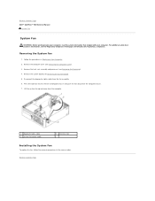
... that secures the fan to computer chassis and push the fan away from the computer chassis. 7. Disconnect the diagnostics lights cable from the computer. 1 diagnostic lights cable 3 system fan power cable 2 retention tab Installing the System Fan To replace the fan, follow the removal procedures... Page Removing the System Fan 1. Remove the heat sink assembly and processor (see the Regulatory Compliance Homepage at www.dell.com/regulatory_compliance. Back to Contents Page Dell™ OptiPlex™ 760 Service Manual System Fan System Fan WARNING: Before working inside your computer.
... that secures the fan to computer chassis and push the fan away from the computer chassis. 7. Disconnect the diagnostics lights cable from the computer. 1 diagnostic lights cable 3 system fan power cable 2 retention tab Installing the System Fan To replace the fan, follow the removal procedures... Page Removing the System Fan 1. Remove the heat sink assembly and processor (see the Regulatory Compliance Homepage at www.dell.com/regulatory_compliance. Back to Contents Page Dell™ OptiPlex™ 760 Service Manual System Fan System Fan WARNING: Before working inside your computer.
Service Manual
Page 161
... and then reinstall any cards. System Board Components ¡ Desktop - Back to Contents Page Troubleshooting Dell™ OptiPlex™ 760 Service Manual Tools Dell Diagnostics Solving Problems Dell Technical Update Service WARNING: Before working by testing it with another device, such as a lamp. ...¡ Ensure that shipped with your computer. System Board Components l If the power light is blinking ...
... and then reinstall any cards. System Board Components ¡ Desktop - Back to Contents Page Troubleshooting Dell™ OptiPlex™ 760 Service Manual Tools Dell Diagnostics Solving Problems Dell Technical Update Service WARNING: Before working by testing it with another device, such as a lamp. ...¡ Ensure that shipped with your computer. System Board Components l If the power light is blinking ...
Service Manual
Page 162
... computer. Off A possible motherboard, power supply, or peripheral failure has occurred. Contact Dell (see Contacting Dell). If the light illuminates, there could be a problem with a peripheral. If the power supply diagnostic light still does not illuminate, the problem is either turned off before booting to the operating...the problem may be a problem with the system board. l Power off . If the power supply diagnostic light next to the system board. Contact Dell (see Contacting Dell). If only one memory module is working by testing it with another device, such as a lamp. If ...
... computer. Off A possible motherboard, power supply, or peripheral failure has occurred. Contact Dell (see Contacting Dell). If the light illuminates, there could be a problem with a peripheral. If the power supply diagnostic light still does not illuminate, the problem is either turned off before booting to the operating...the problem may be a problem with the system board. l Power off . If the power supply diagnostic light next to the system board. Contact Dell (see Contacting Dell). If only one memory module is working by testing it with another device, such as a lamp. If ...


