
Setup and Quick Reference Guide
Page 7
About Your Computer Desktop - Front View 1 2 3 4 5 11 10 98 76 1 optical drive 3 USB 2.0 connectors (2) 5 power button, power light 7 network-connectivity light 9 headphone connector 11 floppy drive or Media Card Reader (optional) 2 optical-drive eject button 4 hard-drive activity light 6 diagnostic lights (4) 8 microphone connector 10 optional floppy drive eject button About Your Computer 7
About Your Computer Desktop - Front View 1 2 3 4 5 11 10 98 76 1 optical drive 3 USB 2.0 connectors (2) 5 power button, power light 7 network-connectivity light 9 headphone connector 11 floppy drive or Media Card Reader (optional) 2 optical-drive eject button 4 hard-drive activity light 6 diagnostic lights (4) 8 microphone connector 10 optional floppy drive eject button About Your Computer 7
Setup and Quick Reference Guide
Page 10
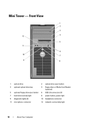
Mini Tower - Front View 1 2 3 4 12 5 11 6 10 7 9 8 1 optical drive 3 optional optical drive bay 5 optional floppy drive eject button 7 hard-drive activity light 9 diagnostic lights (4) 11 microphone connector 2 optical-drive eject button 4 floppy drive or Media Card Reader (optional) 6 USB 2.0 connectors (2) 8 power button, power light 10 headphone connector 12 network-connectivity light 10 About Your Computer
Mini Tower - Front View 1 2 3 4 12 5 11 6 10 7 9 8 1 optical drive 3 optional optical drive bay 5 optional floppy drive eject button 7 hard-drive activity light 9 diagnostic lights (4) 11 microphone connector 2 optical-drive eject button 4 floppy drive or Media Card Reader (optional) 6 USB 2.0 connectors (2) 8 power button, power light 10 headphone connector 12 network-connectivity light 10 About Your Computer

Setup and Quick Reference Guide
Page 13
Front View 1 2 3 4 5 6 11 10 9 8 7 1 optical drive 2 optical-drive eject button 3 USB 2.0 connectors (2) 4 network-connectivity light 5 diagnostic lights (4) 6 hard-drive activity light 7 power button, power light 8 microphone connector 9 headphone connector 10 optional floppy drive eject button 11 floppy drive or Media Card Reader (optional) About Your Computer 13 Small Form Factor -
Front View 1 2 3 4 5 6 11 10 9 8 7 1 optical drive 2 optical-drive eject button 3 USB 2.0 connectors (2) 4 network-connectivity light 5 diagnostic lights (4) 6 hard-drive activity light 7 power button, power light 8 microphone connector 9 headphone connector 10 optional floppy drive eject button 11 floppy drive or Media Card Reader (optional) About Your Computer 13 Small Form Factor -

Setup and Quick Reference Guide
Page 14
Back View 1 2 5 4 3 1 padlock rings 3 power connector 5 expansion-card slots (2) 2 cover release latch 4 back-panel connectors Small Form Factor - Back Panel Connectors 1 2 3 4 5 6 7 11 10 1 parallel connector 3 link-integrity light 5 network-activity light 7 line-in connector 9 VGA video connector 11 DisplayPort connector 14 About Your Computer 9 8 2 serial connector 4 network connector 6 line-out connector 8 USB 2.0 connectors (6) 10 eSATA connector Small Form Factor -
Back View 1 2 5 4 3 1 padlock rings 3 power connector 5 expansion-card slots (2) 2 cover release latch 4 back-panel connectors Small Form Factor - Back Panel Connectors 1 2 3 4 5 6 7 11 10 1 parallel connector 3 link-integrity light 5 network-activity light 7 line-in connector 9 VGA video connector 11 DisplayPort connector 14 About Your Computer 9 8 2 serial connector 4 network connector 6 line-out connector 8 USB 2.0 connectors (6) 10 eSATA connector Small Form Factor -

Setup and Quick Reference Guide
Page 15
Front View 1 2 34 98 1 USB 2.0 connectors (2) 3 hard drive activity light 5 air vents 7 optical drive 9 air vents 76 5 2 microphone connector 4 power button, power light 6 optical-drive eject button 8 headphone connector Ultra Small Form Factor - Back View 1 2 3 6 1 diagnostic lights (4) 3 security cable slot 5 power connector 5 4 2 cover release knob 4 back-panel connectors 6 air vent About Your Computer 15 Ultra Small Form Factor -
Front View 1 2 34 98 1 USB 2.0 connectors (2) 3 hard drive activity light 5 air vents 7 optical drive 9 air vents 76 5 2 microphone connector 4 power button, power light 6 optical-drive eject button 8 headphone connector Ultra Small Form Factor - Back View 1 2 3 6 1 diagnostic lights (4) 3 security cable slot 5 power connector 5 4 2 cover release knob 4 back-panel connectors 6 air vent About Your Computer 15 Ultra Small Form Factor -

Setup and Quick Reference Guide
Page 24
... power adapter to the computer and/or reset the power adapter by disconnecting and reconnecting the plug to the computer. • amber light - The AC power adapter has a status light that the power adapter is connected to an AC power outlet but not to the power outlet. solid amber indicates that is... power outlet. 24 Setting Up Your Computer solid green indicates that the power adapter is green or amber for the following different states: • green light - 1 2 1 grounding source (screw) 2 metal ground connector 4 Connect the AC power cable to the computer.
... power adapter to the computer and/or reset the power adapter by disconnecting and reconnecting the plug to the computer. • amber light - The AC power adapter has a status light that the power adapter is connected to an AC power outlet but not to the power outlet. solid amber indicates that is... power outlet. 24 Setting Up Your Computer solid green indicates that the power adapter is green or amber for the following different states: • green light - 1 2 1 grounding source (screw) 2 metal ground connector 4 Connect the AC power cable to the computer.

Setup and Quick Reference Guide
Page 41
... to the SATA hard drive or CD/DVD. off (no light) - Blinking green in sleep state; Drive activity light green light - The computer is reading data from or writing data to the network. A solid amber light when the computer does not start initialization. Connectors (continued) Processor...connector one 40-pin connector one 775-pin connector one 4-pin connector one 24-pin connector Controls and Lights Front of computer: Power button push button Power light green light - Specifications 41 solid green for power-on page 46). A good connection exists between the network ...
... to the SATA hard drive or CD/DVD. off (no light) - Blinking green in sleep state; Drive activity light green light - The computer is reading data from or writing data to the network. A solid amber light when the computer does not start initialization. Connectors (continued) Processor...connector one 40-pin connector one 775-pin connector one 4-pin connector one 24-pin connector Controls and Lights Front of computer: Power button push button Power light green light - Specifications 41 solid green for power-on page 46). A good connection exists between the network ...
Setup and Quick Reference Guide
Page 42
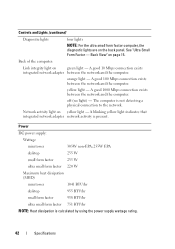
... connection exists integrated network adapter between the network and the computer. The computer is present. Network activity light on page 15. Back View" on yellow light - yellow light - Power DC power supply: Wattage mini tower 305W non-EPA; 255W EPA desktop 255 W small ... Heat dissipation is calculated by using the power supply wattage rating. 42 Specifications off (no light) - Back of the computer: Link integrity light on the back panel. Controls and Lights (continued) Diagnostic lights four lights NOTE: For the ultra small form factor computer, the diagnostic...
... connection exists integrated network adapter between the network and the computer. The computer is present. Network activity light on page 15. Back View" on yellow light - yellow light - Power DC power supply: Wattage mini tower 305W non-EPA; 255W EPA desktop 255 W small ... Heat dissipation is calculated by using the power supply wattage rating. 42 Specifications off (no light) - Back of the computer: Link integrity light on the back panel. Controls and Lights (continued) Diagnostic lights four lights NOTE: For the ultra small form factor computer, the diagnostic...

Setup and Quick Reference Guide
Page 46
...THE POWER LIGHT IS GREEN AND THE COMPUTER IS NOT RESPONDING - • Ensure that the display is connected and powered on. • If the display is connected and powered on, see (see your computer. The computer is in a program, see the Regulatory Compliance Homepage at support.dell.com). ... message may help support personnel to diagnose and fix the problem(s). • If an error message occurs in sleep mode. IF T H E POWER LIGHT IS O F F - For additional safety best practices information, see the program documentation. Press a key on the screen, write down the exact message...
...THE POWER LIGHT IS GREEN AND THE COMPUTER IS NOT RESPONDING - • Ensure that the display is connected and powered on. • If the display is connected and powered on, see (see your computer. The computer is in a program, see the Regulatory Compliance Homepage at support.dell.com). ... message may help support personnel to diagnose and fix the problem(s). • If an error message occurs in sleep mode. IF T H E POWER LIGHT IS O F F - For additional safety best practices information, see the program documentation. Press a key on the screen, write down the exact message...

Setup and Quick Reference Guide
Page 74
... setting up, 28 L license label, 64 P phone numbers, 71 power power light conditions, 46 troubleshooting, 46 problems restore to previous state, 57 M media Drivers and Utilities, 63 operating system, 63 memory troubleshooting, 47 N networks, 23 connecting, 23 O operating system Dell Factory Image Restore, 58 media, 60 reinstalling, 63 System Restore, 56 Operating...
... setting up, 28 L license label, 64 P phone numbers, 71 power power light conditions, 46 troubleshooting, 46 problems restore to previous state, 57 M media Drivers and Utilities, 63 operating system, 63 memory troubleshooting, 47 N networks, 23 connecting, 23 O operating system Dell Factory Image Restore, 58 media, 60 reinstalling, 63 System Restore, 56 Operating...
Setup and Quick Reference Guide
Page 75
specifications all, 35 audio, 36 connectors, 39 controls and lights, 41 drives, 37 environmental, 44 expansion bus, 36 memory, 35 physical, 43 power, 42 processor, 35 system information, 35 video, 36 support, 65 contacting Dell, 71 DellConnect, 66 online services, 66 regional, 66 technical ...Conditions, 64 transferring information to a new computer, 30 troubleshooting, 45, 64 blue screen, 49 computer not responding, 48 Dell Diagnostics, 50 memory, 47 power, 46 power light conditions, 46 program crashes, 48 programs and Windows compatibility, 48 restore to previous state, 56-57 software, 48-49...
specifications all, 35 audio, 36 connectors, 39 controls and lights, 41 drives, 37 environmental, 44 expansion bus, 36 memory, 35 physical, 43 power, 42 processor, 35 system information, 35 video, 36 support, 65 contacting Dell, 71 DellConnect, 66 online services, 66 regional, 66 technical ...Conditions, 64 transferring information to a new computer, 30 troubleshooting, 45, 64 blue screen, 49 computer not responding, 48 Dell Diagnostics, 50 memory, 47 power, 46 power light conditions, 46 program crashes, 48 programs and Windows compatibility, 48 restore to previous state, 56-57 software, 48-49...

Service Manual
Page 28
... front and rear alignment-notches on the processor with the socket, and do not use excessive force when you install the processor. 7. Set the processor lightly in the socket and ensure that the processor is fully seated in the socket, close the processor cover. When the processor is positioned correctly. 8. Apply...
... front and rear alignment-notches on the processor with the socket, and do not use excessive force when you install the processor. 7. Set the processor lightly in the socket and ensure that the processor is fully seated in the socket, close the processor cover. When the processor is positioned correctly. 8. Apply...
Service Manual
Page 58
...basic data unit used for a SATA hard drive Host Controller which allows the storage driver to Contents Page Glossary Dell™ OptiPlex™ 760 Service Manual Terms in your computer when you understand what effect these settings have a bootable CD or floppy ...water. In case your particular computer. A measurement of many processor operations. L1 cache - advanced configuration and power interface - ambient light sensor - A dedicated graphics port that facilitates temporary imports into the processor architecture. An interface for video-related tasks. A program ...
...basic data unit used for a SATA hard drive Host Controller which allows the storage driver to Contents Page Glossary Dell™ OptiPlex™ 760 Service Manual Terms in your computer when you understand what effect these settings have a bootable CD or floppy ...water. In case your particular computer. A measurement of many processor operations. L1 cache - advanced configuration and power interface - ambient light sensor - A dedicated graphics port that facilitates temporary imports into the processor architecture. An interface for video-related tasks. A program ...

Service Manual
Page 61
...can share the same IRQ assignment, you to access its host server to connect directly to as optical drives, a second battery, or a Dell TravelLite™ module. Mbps - megabyte - IC - Although two devices can be assigned an IRQ. Internet service provider - A computer network ...1 cycle per second - A unit of memory chip capacity that equals 1,048,576 bytes. 1 MB equals 1024 KB. local area network - light-emitting diode - The designation for a fee. megabits per second. A measurement of memory integrated circuits. One million bytes per second - infrared sensor...
...can share the same IRQ assignment, you to access its host server to connect directly to as optical drives, a second battery, or a Dell TravelLite™ module. Mbps - megabyte - IC - Although two devices can be assigned an IRQ. Internet service provider - A computer network ...1 cycle per second - A unit of memory chip capacity that equals 1,048,576 bytes. 1 MB equals 1024 KB. local area network - light-emitting diode - The designation for a fee. megabits per second. A measurement of memory integrated circuits. One million bytes per second - infrared sensor...
Service Manual
Page 63
... readme files provide installation information and describe new product enhancements or corrections that cannot be used to as infrared and light. The sharpness and clarity of the electromagnetic frequency spectrum and are recharged (sometimes also referred to install and configure hardware.... smart card - RTC - serial connector - processor - Sometimes the processor is generated at typical radio frequencies, in Hz, at support.dell.com or when you restart the computer after it first. PS/2 - PXE - pre-boot execution environment - A WfM (Wired for customer...
... readme files provide installation information and describe new product enhancements or corrections that cannot be used to as infrared and light. The sharpness and clarity of the electromagnetic frequency spectrum and are recharged (sometimes also referred to install and configure hardware.... smart card - RTC - serial connector - processor - Sometimes the processor is generated at typical radio frequencies, in Hz, at support.dell.com or when you restart the computer after it first. PS/2 - PXE - pre-boot execution environment - A WfM (Wired for customer...

Service Manual
Page 79
Set the processor lightly in the socket, close the processor cover. When the processor is fully seated in the socket and ensure that the processor is a requirement for ensuring ...
Set the processor lightly in the socket, close the processor cover. When the processor is fully seated in the socket and ensure that the processor is a requirement for ensuring ...

Service Manual
Page 117
... that the heat sink is a requirement for ensuring adequate thermal bonding, which is correctly seated and secure. Install the heat sink assembly: a. Set the processor lightly in the socket, close the processor cover.
... that the heat sink is a requirement for ensuring adequate thermal bonding, which is correctly seated and secure. Install the heat sink assembly: a. Set the processor lightly in the socket, close the processor cover.
Service Manual
Page 133
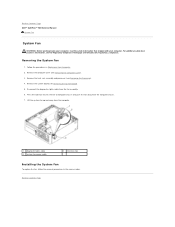
... (see the Regulatory Compliance Homepage at www.dell.com/regulatory_compliance. Remove the system board (see Removing the Computer Cover). 3. Press the tab that shipped with your computer. Removing the System Fan 1. Disconnect the diagnostics lights cable from the computer chassis. 7. Remove ... from the computer. 1 diagnostic lights cable 3 system fan power cable 2 retention tab Installing the System Fan To replace the fan, follow the removal procedures in Working on Your Computer. 2. Back to Contents Page Dell™ OptiPlex™ 760 Service Manual System Fan System Fan...
... (see the Regulatory Compliance Homepage at www.dell.com/regulatory_compliance. Remove the system board (see Removing the Computer Cover). 3. Press the tab that shipped with your computer. Removing the System Fan 1. Disconnect the diagnostics lights cable from the computer chassis. 7. Remove ... from the computer. 1 diagnostic lights cable 3 system fan power cable 2 retention tab Installing the System Fan To replace the fan, follow the removal procedures in Working on Your Computer. 2. Back to Contents Page Dell™ OptiPlex™ 760 Service Manual System Fan System Fan...
Service Manual
Page 161
...possible causes of interference are securely connected to the system board. Back to Contents Page Troubleshooting Dell™ OptiPlex™ 760 Service Manual Tools Dell Diagnostics Solving Problems Dell Technical Update Service WARNING: Before working by testing it with your location, if applicable. ...¡ Ensure that the processor power cable is securely connected to the system board. l If the power light...
...possible causes of interference are securely connected to the system board. Back to Contents Page Troubleshooting Dell™ OptiPlex™ 760 Service Manual Tools Dell Diagnostics Solving Problems Dell Technical Update Service WARNING: Before working by testing it with your location, if applicable. ...¡ Ensure that the processor power cable is securely connected to the system board. l If the power light...
Service Manual
Page 162
... to boot, inspect the processor socket for more memory modules are present on properly. Contact Dell (see Contacting Dell). If the light illuminates, there could be a problem with a known good processor. Contact Dell (see Contacting Dell). If the computer still fails to the switch does not illuminate, disconnect all internal and external peripherals, and press...
... to boot, inspect the processor socket for more memory modules are present on properly. Contact Dell (see Contacting Dell). If the light illuminates, there could be a problem with a known good processor. Contact Dell (see Contacting Dell). If the computer still fails to the switch does not illuminate, disconnect all internal and external peripherals, and press...


