Quick Reference Guide
Page 3
... . . 26 Small Form Factor Computer - Back View 17 Mini Tower Computer - Back-Panel Connectors . . 24 Small Form Factor Computer - Back-Panel Connectors 30 Removing the Computer Cover 32 Before You Begin 32 Mini Tower Computer 34 Desktop Computer 36 Small Form Factor Computer 38 Inside Your... Computer 39 Mini Tower Computer 39 Desktop Computer 43 Small Form Factor Computer 47 Contents 3 Back View 23 ...
... . . 26 Small Form Factor Computer - Back View 17 Mini Tower Computer - Back-Panel Connectors . . 24 Small Form Factor Computer - Back-Panel Connectors 30 Removing the Computer Cover 32 Before You Begin 32 Mini Tower Computer 34 Desktop Computer 36 Small Form Factor Computer 38 Inside Your... Computer 39 Mini Tower Computer 39 Desktop Computer 43 Small Form Factor Computer 47 Contents 3 Back View 23 ...
Quick Reference Guide
Page 17
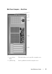
Back View 1 2 3 4 5 6 1 cover release latch 2 padlock ring This latch allows you to lock the computer cover. Mini Tower Computer - Quick Reference Guide 17 Insert a padlock to open the computer cover.
Back View 1 2 3 4 5 6 1 cover release latch 2 padlock ring This latch allows you to lock the computer cover. Mini Tower Computer - Quick Reference Guide 17 Insert a padlock to open the computer cover.
Quick Reference Guide
Page 18
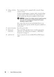
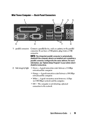
... power available in your location. 4 power connector Insert the power cable. 5 back-panel connectors Plug serial, USB, and other devices into the appropriate connectors. See "Mini Tower Computer - To help avoid damaging a computer with a manual voltage selection switch, set to operate with a manual voltage- NOTICE: In Japan, the voltage selection switch must...
... power available in your location. 4 power connector Insert the power cable. 5 back-panel connectors Plug serial, USB, and other devices into the appropriate connectors. See "Mini Tower Computer - To help avoid damaging a computer with a manual voltage selection switch, set to operate with a manual voltage- NOTICE: In Japan, the voltage selection switch must...
Quick Reference Guide
Page 19
... device, such as a printer, to the network. NOTE: The integrated parallel connector is not detecting a physical connection to the parallel connector. Quick Reference Guide 19 Mini Tower Computer -
... device, such as a printer, to the network. NOTE: The integrated parallel connector is not detecting a physical connection to the parallel connector. Quick Reference Guide 19 Mini Tower Computer -
Quick Reference Guide
Page 33
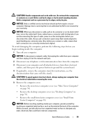
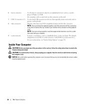
...computer and all attached devices from the electrical outlet before removing the cover. 5 Remove the computer cover: • Remove the mini tower computer cover (see "Mini Tower Computer" on page 34). • Remove the desktop computer cover (see "Desktop Computer" on page 36). • Remove ...the small form factor computer cover (see the documentation that could harm internal components. NOTICE: When you connect a cable, ensure that is not authorized by Dell...
...computer and all attached devices from the electrical outlet before removing the cover. 5 Remove the computer cover: • Remove the mini tower computer cover (see "Mini Tower Computer" on page 34). • Remove the desktop computer cover (see "Desktop Computer" on page 36). • Remove ...the small form factor computer cover (see the documentation that could harm internal components. NOTICE: When you connect a cable, ensure that is not authorized by Dell...
Quick Reference Guide
Page 34
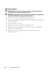
Mini Tower Computer CAUTION: Before you lift the cover. 5 Grip the sides of the procedures in this section, follow the safety instructions in "Before You Begin" on ...
Mini Tower Computer CAUTION: Before you lift the cover. 5 Grip the sides of the procedures in this section, follow the safety instructions in "Before You Begin" on ...
Quick Reference Guide
Page 39
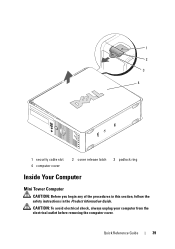
CAUTION: To avoid electrical shock, always unplug your computer from the electrical outlet before removing the computer cover. Quick Reference Guide 39 1 2 3 4 1 security cable slot 4 computer cover 2 cover release latch 3 padlock ring Inside Your Computer Mini Tower Computer CAUTION: Before you begin any of the procedures in this section, follow the safety instructions in the Product Information Guide.
CAUTION: To avoid electrical shock, always unplug your computer from the electrical outlet before removing the computer cover. Quick Reference Guide 39 1 2 3 4 1 security cable slot 4 computer cover 2 cover release latch 3 padlock ring Inside Your Computer Mini Tower Computer CAUTION: Before you begin any of the procedures in this section, follow the safety instructions in the Product Information Guide.
User's Guide
Page 3
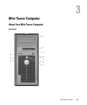
... Tools 19 Turning Off Your Computer 19 Before Working Inside Your Computer 20 3 Mini Tower Computer 21 About Your Mini Tower Computer 21 Front View 21 Back View 23 Back-Panel Connectors 25 Inside Your Computer 26 System Board Components 28 Mini Tower Computer (Model #DCSM) Specifications 31 I/O Panel 37 Removing the I/O Panel 37 Replacing the...
... Tools 19 Turning Off Your Computer 19 Before Working Inside Your Computer 20 3 Mini Tower Computer 21 About Your Mini Tower Computer 21 Front View 21 Back View 23 Back-Panel Connectors 25 Inside Your Computer 26 System Board Components 28 Mini Tower Computer (Model #DCSM) Specifications 31 I/O Panel 37 Removing the I/O Panel 37 Replacing the...
User's Guide
Page 6
6 Advanced Features 249 LegacySelect Technology Control 249 Manageability 249 Alert Standard Format 249 Dell OpenManage™ IT Assistant 250 Dell OpenManage Client Instrumentation 250 Security 250 Chassis Intrusion Detection 250 Option Settings 251 Padlock Ring and Security Cable ...Entering System Setup 257 System Setup Options 258 Booting to a USB Device 264 Memory Key 264 Floppy Drive 264 Jumper Settings 265 Mini Tower, Desktop, and Small Form Factor Computers 265 Clearing Forgotten Passwords 265 Clearing CMOS Settings 266 HyperTransport™ and Dual-Core Technology ...
6 Advanced Features 249 LegacySelect Technology Control 249 Manageability 249 Alert Standard Format 249 Dell OpenManage™ IT Assistant 250 Dell OpenManage Client Instrumentation 250 Security 250 Chassis Intrusion Detection 250 Option Settings 251 Padlock Ring and Security Cable ...Entering System Setup 257 System Setup Options 258 Booting to a USB Device 264 Memory Key 264 Floppy Drive 264 Jumper Settings 265 Mini Tower, Desktop, and Small Form Factor Computers 265 Clearing Forgotten Passwords 265 Clearing CMOS Settings 266 HyperTransport™ and Dual-Core Technology ...
User's Guide
Page 7
...NVIDIA MediaShield 272 Enabling Cool 'n' Quiet™ Technology 275 7 Chassis Intrusion Switch 277 Removing the Chassis Intrusion Switch 277 Mini Tower Computer 278 Desktop Computer 279 Small Form Factor Computer 280 Replacing the Chassis Intrusion Switch 280 Resetting the Chassis Intrusion Detector ... 283 Replacing the Battery 283 9 Replacing the System Board 287 Removing the System Board: Mini Tower, Desktop, and Small Form Factor Computers 287 Replacing the System Board: Mini Tower, Desktop, and Small Form Factor Computers 290 10 Memory 291 DDR2 Memory Overview 291 Addressing...
...NVIDIA MediaShield 272 Enabling Cool 'n' Quiet™ Technology 275 7 Chassis Intrusion Switch 277 Removing the Chassis Intrusion Switch 277 Mini Tower Computer 278 Desktop Computer 279 Small Form Factor Computer 280 Replacing the Chassis Intrusion Switch 280 Resetting the Chassis Intrusion Detector ... 283 Replacing the Battery 283 9 Replacing the System Board 287 Removing the System Board: Mini Tower, Desktop, and Small Form Factor Computers 287 Replacing the System Board: Mini Tower, Desktop, and Small Form Factor Computers 290 10 Memory 291 DDR2 Memory Overview 291 Addressing...
User's Guide
Page 20
...to servicing that could harm internal components. 20 Before You Begin if you begin any static electricity that is not authorized by Dell is not covered by your computer and all attached devices from the electrical outlet before you are disconnecting this type of the procedures...with locking tabs; Before Working Inside Your Computer Use the following steps before removing the cover. 5 Remove the computer cover: • Remove the mini tower computer cover (see "Removing the Computer Cover" on page 39). • Remove the desktop computer cover (see "Removing the Computer Cover" ...
...to servicing that could harm internal components. 20 Before You Begin if you begin any static electricity that is not authorized by Dell is not covered by your computer and all attached devices from the electrical outlet before you are disconnecting this type of the procedures...with locking tabs; Before Working Inside Your Computer Use the following steps before removing the cover. 5 Remove the computer cover: • Remove the mini tower computer cover (see "Removing the Computer Cover" on page 39). • Remove the desktop computer cover (see "Removing the Computer Cover" ...
User's Guide
Page 21
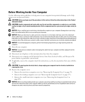
3 Mini Tower Computer About Your Mini Tower Computer Front View 1 2 3 10 4 9 5 8 6 7 Mini Tower Computer 21
3 Mini Tower Computer About Your Mini Tower Computer Front View 1 2 3 10 4 9 5 8 6 7 Mini Tower Computer 21
User's Guide
Page 22
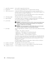
... devices (see "Diagnostic Lights" on the computer. See "System Lights" on page 267. Press this drive. See "Power Problems" on booting to attach a microphone. 22 Mini Tower Computer This light flickers when the hard drive is turned off the computer by pressing the power button. 1 optical drive (optional) 2 Flexbay drive 3 USB 2.0 connectors...
... devices (see "Diagnostic Lights" on the computer. See "System Lights" on page 267. Press this drive. See "Power Problems" on booting to attach a microphone. 22 Mini Tower Computer This light flickers when the hard drive is turned off the computer by pressing the power button. 1 optical drive (optional) 2 Flexbay drive 3 USB 2.0 connectors...
User's Guide
Page 24
... into the appropriate connectors. NOTICE: In Japan, the voltage selection switch must be set the switch for any installed PCI and PCI Express cards. 24 Mini Tower Computer Also, ensure that most closely matches the AC power available in Japan is equipped with the AC power available in your location. . See "Back...
... into the appropriate connectors. NOTICE: In Japan, the voltage selection switch must be set the switch for any installed PCI and PCI Express cards. 24 Mini Tower Computer Also, ensure that most closely matches the AC power available in Japan is equipped with the AC power available in your location. . See "Back...
User's Guide
Page 25
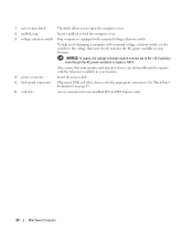
... device. On computers with a sound card, use Category 5 wiring and connectors for your computer. A high volume of a network cable to be in a steady "on" state. Mini Tower Computer 25 If you have a USB printer, plug it into the network connector. A click indicates that you must use the connector on the card. If...
... device. On computers with a sound card, use Category 5 wiring and connectors for your computer. A high volume of a network cable to be in a steady "on" state. Mini Tower Computer 25 If you have a USB printer, plug it into the network connector. A click indicates that you must use the connector on the card. If...
User's Guide
Page 26
CAUTION: To avoid electrical shock, always unplug your computer from the system board. 26 Mini Tower Computer On computers with your VGA-compatible monitor into the blue connector. NOTE: If you do not accidentally disconnect cables from the electrical outlet before ...
CAUTION: To avoid electrical shock, always unplug your computer from the system board. 26 Mini Tower Computer On computers with your VGA-compatible monitor into the blue connector. NOTE: If you do not accidentally disconnect cables from the electrical outlet before ...

User's Guide
Page 27
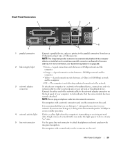
3 2 1 4 5 1 optical drive 4 chassis intrusion switch (optional) 7 hard drive 2 floppy drive 5 system board 6 7 3 power supply 6 heat sink assembly Mini Tower Computer 27
3 2 1 4 5 1 optical drive 4 chassis intrusion switch (optional) 7 hard drive 2 floppy drive 5 system board 6 7 3 power supply 6 heat sink assembly Mini Tower Computer 27
User's Guide
Page 31
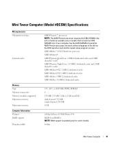
Mini Tower Computer (Model #DCSM) Specifications . AMD Athlon™ 64 X2 Dual-Core processor AMD Athlon 64 AMD Phenom Quad-Core: 2-MB L2 dedicated cache and 2-MB ... Internal cache AMD Phenom™ processors NOTE: The AMD Phenom processor requires the 8-Mb NVRAM chip and is available only for select models. 64 bits Mini Tower Computer 31 If your computer has the 8-Mb NVRAM chip and the AMD Phenom processor, the word enhanced appears in the title on models that...
Mini Tower Computer (Model #DCSM) Specifications . AMD Athlon™ 64 X2 Dual-Core processor AMD Athlon 64 AMD Phenom Quad-Core: 2-MB L2 dedicated cache and 2-MB ... Internal cache AMD Phenom™ processors NOTE: The AMD Phenom processor requires the 8-Mb NVRAM chip and is available only for select models. 64 bits Mini Tower Computer 31 If your computer has the 8-Mb NVRAM chip and the AMD Phenom processor, the word enhanced appears in the title on models that...
User's Guide
Page 32
...; 24-bit digital-to-analog two SATA controllers supporting two devices each, including two 3.5-inch hard drives PCI 2.3 PCI Express 1.0A SATA 1.0A and 2.0 USB 2.0 Mini Tower Computer 32 If your computer has the 8-Mb NVRAM chip and the AMD Phenom processor, the word enhanced appears in the title on models that...
...; 24-bit digital-to-analog two SATA controllers supporting two devices each, including two 3.5-inch hard drives PCI 2.3 PCI Express 1.0A SATA 1.0A and 2.0 USB 2.0 Mini Tower Computer 32 If your computer has the 8-Mb NVRAM chip and the AMD Phenom processor, the word enhanced appears in the title on models that...
User's Guide
Page 33
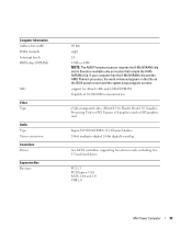
Mini Tower Computer 33 Expansion Bus Bus speed Cards: PCI: connectors connector size connector data width (maximum) PCI Express: connectors power connector size connector data width (maximum) ...
Mini Tower Computer 33 Expansion Bus Bus speed Cards: PCI: connectors connector size connector data width (maximum) PCI Express: connectors power connector size connector data width (maximum) ...


