Quick Reference Guide
Page 18
..., ensure that most closely matches the AC power available in your location. Back-Panel Connectors" on page 19. 6 card slots (4) Access connectors for the voltage that your monitor and attached devices are electrically rated to the 115-V position even though the AC power available in Japan is ...
..., ensure that most closely matches the AC power available in your location. Back-Panel Connectors" on page 19. 6 card slots (4) Access connectors for the voltage that your monitor and attached devices are electrically rated to the 115-V position even though the AC power available in Japan is ...
Quick Reference Guide
Page 23
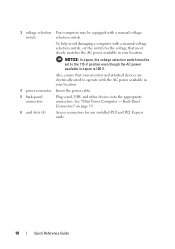
Insert an optical drive (if supported) into the appropriate connectors (see "Desktop Computer - Insert the power cable. Desktop Computer - Back View 1 2 3 4 5 6 1 card slots (3) 2 back-panel connectors 3 power connector Access connectors for any installed PCI and PCI Express cards. Quick Reference Guide 23 This bay accommodates an optional floppy drive, media card reader, or second hard ...
Insert an optical drive (if supported) into the appropriate connectors (see "Desktop Computer - Insert the power cable. Desktop Computer - Back View 1 2 3 4 5 6 1 card slots (3) 2 back-panel connectors 3 power connector Access connectors for any installed PCI and PCI Express cards. Quick Reference Guide 23 This bay accommodates an optional floppy drive, media card reader, or second hard ...
Quick Reference Guide
Page 27
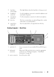
... hard drive is established. Quick Reference Guide 27 NOTICE: If your operating system has ACPI enabled, when you use the back USB connectors for devices that typically remain connected, such as joysticks or cameras, or for bootable USB devices (see "System Setup Program" in your...). It is recommended that you press the power button the computer will perform an operating system shutdown. 3 Dell badge This badge can also rotate the badge using the slot provided near the bottom of your online User's Guide for instructions for more information, see "Diagnostic Lights" ...
... hard drive is established. Quick Reference Guide 27 NOTICE: If your operating system has ACPI enabled, when you use the back USB connectors for devices that typically remain connected, such as joysticks or cameras, or for bootable USB devices (see "System Setup Program" in your...). It is recommended that you press the power button the computer will perform an operating system shutdown. 3 Dell badge This badge can also rotate the badge using the slot provided near the bottom of your online User's Guide for instructions for more information, see "Diagnostic Lights" ...
Quick Reference Guide
Page 29
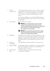
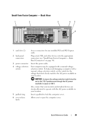
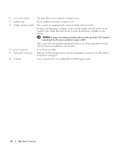
Plug serial, USB, and other devices into the appropriate connectors (see "Small Form Factor Computer - To help avoid damaging a computer with a manual voltage selection switch, set to operate with a manual voltageselection ...a padlock to open the computer cover. Insert the power cable. Back View 1 2 3 45 6 1 card slots (2) 2 back-panel connectors 3 power connector 4 voltage selection switch 5 padlock ring 6 cover release latch Access connectors for the voltage that your monitor and attached devices are electrically rated to the 115-V position even though the AC...
Plug serial, USB, and other devices into the appropriate connectors (see "Small Form Factor Computer - To help avoid damaging a computer with a manual voltage selection switch, set to operate with a manual voltageselection ...a padlock to open the computer cover. Insert the power cable. Back View 1 2 3 45 6 1 card slots (2) 2 back-panel connectors 3 power connector 4 voltage selection switch 5 padlock ring 6 cover release latch Access connectors for the voltage that your monitor and attached devices are electrically rated to the 115-V position even though the AC...
User's Guide
Page 24
... selection switch, set to lock the computer cover. 3 voltage selection switch Your computer is 100 V. See "Back-Panel Connectors" on page 25. 6 card slots Access connectors for the voltage that most closely matches the AC power available in your location. 4 power... connector Insert the power cable. 5 back-panel connectors Plug serial, USB, and other devices into the appropriate connectors. To help avoid damaging a computer with the AC power...
... selection switch, set to lock the computer cover. 3 voltage selection switch Your computer is 100 V. See "Back-Panel Connectors" on page 25. 6 card slots Access connectors for the voltage that most closely matches the AC power available in your location. 4 power... connector Insert the power cable. 5 back-panel connectors Plug serial, USB, and other devices into the appropriate connectors. To help avoid damaging a computer with the AC power...
User's Guide
Page 33
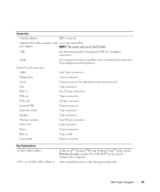
Mini Tower Computer 33 Expansion Bus Bus speed Cards: PCI: connectors connector size connector data width (maximum) PCI Express: connectors power connector size connector data width (maximum) Drives Externally accessible Internally accessible Connectors External connectors: Serial Parallel Video Optional DVI PCI: 133 MB/s PCI Express x16: 40 GB/s bidirectional speed PCI ... hard drives two 5.25-inch drive bays two bays for 1-inch-high hard drives 9-pin connector; 16550C-compatible 25-hole connector (bidirectional) 15-hole VGA connector 36-pin connector NOTE: This option uses one of the PCI...
Mini Tower Computer 33 Expansion Bus Bus speed Cards: PCI: connectors connector size connector data width (maximum) PCI Express: connectors power connector size connector data width (maximum) Drives Externally accessible Internally accessible Connectors External connectors: Serial Parallel Video Optional DVI PCI: 133 MB/s PCI Express x16: 40 GB/s bidirectional speed PCI ... hard drives two 5.25-inch drive bays two bays for 1-inch-high hard drives 9-pin connector; 16550C-compatible 25-hole connector (bidirectional) 15-hole VGA connector 36-pin connector NOTE: This option uses one of the PCI...
User's Guide
Page 34
... serial two 6-pin mini-DINs port adapter NOTE: This option uses one of the PCI slots. two front-panel connectors for headphones and microphone System board connectors: SATA four 7-pin connectors Floppy drive 34-pin connector Serial 24-pin connector for line-in and line-out; USB two front-panel and five back-panel USB 2.0-compliant...
... serial two 6-pin mini-DINs port adapter NOTE: This option uses one of the PCI slots. two front-panel connectors for headphones and microphone System board connectors: SATA four 7-pin connectors Floppy drive 34-pin connector Serial 24-pin connector for line-in and line-out; USB two front-panel and five back-panel USB 2.0-compliant...
User's Guide
Page 41
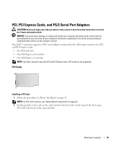
...supported. MiniTower Computer 41 Your Dell™ computer supports a PS/2 serial adapter and provides the following connectors for PCI and PCI Express cards. • Two PCI card slots • One PCI Express x16 card slot • One PCI Express x1 card slot NOTE: Your Dell computer uses only PCI and... PCI Express slots. NOTE: For PCI card locations, see "System...
...supported. MiniTower Computer 41 Your Dell™ computer supports a PS/2 serial adapter and provides the following connectors for PCI and PCI Express cards. • Two PCI card slots • One PCI Express x16 card slot • One PCI Express x1 card slot NOTE: Your Dell computer uses only PCI and... PCI Express slots. NOTE: For PCI card locations, see "System...
User's Guide
Page 42
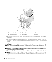
... shock, be sure to unplug your computer 6 Place the card in the slot. 2 1 3 4 6 5 1 card retention latch 4 card-edge connector 2 alignment guide 5 card connector 3 card 6 release tab 3 If you are connected to a network. NOTE: If the card is fully seated in the connector and press down firmly. Ensure that came with step 6. 5 Prepare the new...
... shock, be sure to unplug your computer 6 Place the card in the slot. 2 1 3 4 6 5 1 card retention latch 4 card-edge connector 2 alignment guide 5 card connector 3 card 6 release tab 3 If you are connected to a network. NOTE: If the card is fully seated in the connector and press down firmly. Ensure that came with step 6. 5 Prepare the new...

User's Guide
Page 43
... jack and then plug it into the computer. 2 1 3 4 1 fully seated card 2 4 bracket caught outside of the computer (see "Back-Panel Connectors" on page 25). 11 If you installed a sound card: a Enter system setup, select Integrated Audio from the Onboard Devices group, and change the setting ...b Connect external audio devices to the card. 9 Replace the computer cover (see "System Setup" on the back panel of slot not fully seated card 3 bracket within slot 7 Secure the card(s) by closing properly or cause damage to the equipment. 8 Connect any cables that should be attached to ...
... jack and then plug it into the computer. 2 1 3 4 1 fully seated card 2 4 bracket caught outside of the computer (see "Back-Panel Connectors" on page 25). 11 If you installed a sound card: a Enter system setup, select Integrated Audio from the Onboard Devices group, and change the setting ...b Connect external audio devices to the card. 9 Replace the computer cover (see "System Setup" on the back panel of slot not fully seated card 3 bracket within slot 7 Secure the card(s) by closing properly or cause damage to the equipment. 8 Connect any cables that should be attached to ...
User's Guide
Page 44
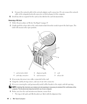
...are removing the card permanently, install a filler bracket in the empty card-slot opening. The latch will remain in the card documentation. Do not connect the network cable to the integrated network connector on the card retention latch from the inside to pivot the latch open...6 5 1 card retention latch 4 card-edge connector 2 alignment guide 5 card connector 3 card 6 release tab 3 If necessary, disconnect any drivers required for the card as described in the open . NOTE: Installing filler brackets over empty card-slot openings is necessary to maintain FCC certification of the...
...are removing the card permanently, install a filler bracket in the empty card-slot opening. The latch will remain in the card documentation. Do not connect the network cable to the integrated network connector on the card retention latch from the inside to pivot the latch open...6 5 1 card retention latch 4 card-edge connector 2 alignment guide 5 card connector 3 card 6 release tab 3 If necessary, disconnect any drivers required for the card as described in the open . NOTE: Installing filler brackets over empty card-slot openings is necessary to maintain FCC certification of the...
User's Guide
Page 45
... setup, select Integrated NIC from the Onboard Devices group, and change the setting to the integrated network connector on the back panel of slot not fully seated card 3 bracket within slot 7 Secure the card(s) by closing the card retention latch and snapping it into place. 8 Replace ...the alignment guide. 2 1 3 4 1 fully seated card 2 4 bracket caught outside of the computer. b Connect external audio devices to the audio connectors on the back panel of the computer. 11 If you removed a sound card: a Enter system setup, select Integrated Audio from the Onboard Devices group,...
... setup, select Integrated NIC from the Onboard Devices group, and change the setting to the integrated network connector on the back panel of slot not fully seated card 3 bracket within slot 7 Secure the card(s) by closing the card retention latch and snapping it into place. 8 Replace ...the alignment guide. 2 1 3 4 1 fully seated card 2 4 bracket caught outside of the computer. b Connect external audio devices to the audio connectors on the back panel of the computer. 11 If you removed a sound card: a Enter system setup, select Integrated Audio from the Onboard Devices group,...
User's Guide
Page 47
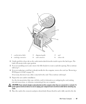
... the computer when they are replacing a card that is fully seated in the open . The latch will remain in the slot. Ensure that came with step 6. 5 Prepare the new card for your computer from its electrical outlet before installing any cables connected ...to create a card-slot opening. 2 1 3 4 6 5 1 card retention latch 4 card-edge connector 2 alignment guide 5 card connector 3 card 6 release tab 2 Gently push the release tab on page 49). Mini Tower Computer 47 If ...
... the computer when they are replacing a card that is fully seated in the open . The latch will remain in the slot. Ensure that came with step 6. 5 Prepare the new card for your computer from its electrical outlet before installing any cables connected ...to create a card-slot opening. 2 1 3 4 6 5 1 card retention latch 4 card-edge connector 2 alignment guide 5 card connector 3 card 6 release tab 2 Gently push the release tab on page 49). Mini Tower Computer 47 If ...
User's Guide
Page 48
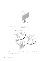
1 1 PCI Express x1 card 2 2 2 PCI Express x1 card connector 1 3 4 1 fully seated card 2 4 bracket caught outside of slot not fully seated card 3 bracket within slot 48 Mini Tower Computer
1 1 PCI Express x1 card 2 2 2 PCI Express x1 card connector 1 3 4 1 fully seated card 2 4 bracket caught outside of slot not fully seated card 3 bracket within slot 48 Mini Tower Computer
User's Guide
Page 50
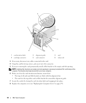
... cover (see "Replacing the Computer Cover" on page 297). 50 Mini Tower Computer NOTE: Installing filler brackets over empty card-slot openings is necessary to the card. 4 Grasp the card by its connector. 5 If you close the card retention mechanism, ensure that: • The tops of all cards and filler brackets are...
... cover (see "Replacing the Computer Cover" on page 297). 50 Mini Tower Computer NOTE: Installing filler brackets over empty card-slot openings is necessary to the card. 4 Grasp the card by its connector. 5 If you close the card retention mechanism, ensure that: • The tops of all cards and filler brackets are...
User's Guide
Page 51
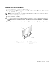
... your computer. 3 Prepare the card for your computer from its electrical outlet before installing any cards. 4 Place the card in the slot. 1 1 PCI Express x16 card 2 2 PCI Express x16 card connector Mini Tower Computer 51 CAUTION: Some network adapters automatically start the computer when they are replacing a PCI Express x16 card, remove... customizing it for installation. To guard against electrical shock, be sure to a network. NOTE: See the documentation that the card is fully seated in the connector and press down firmly.
... your computer. 3 Prepare the card for your computer from its electrical outlet before installing any cards. 4 Place the card in the slot. 1 1 PCI Express x16 card 2 2 PCI Express x16 card connector Mini Tower Computer 51 CAUTION: Some network adapters automatically start the computer when they are replacing a PCI Express x16 card, remove... customizing it for installation. To guard against electrical shock, be sure to a network. NOTE: See the documentation that the card is fully seated in the connector and press down firmly.

User's Guide
Page 53
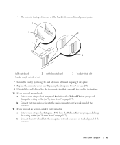
... fully seated card 3 bracket within slot 5 Connect any cables that : • The tops of all cards and filler brackets are flush with the alignment bar. • The notch in connector on the back panel of the card or filler bracket fits around the alignment guide. 7 Secure the card...into place. 8 Replace the computer cover (see "Replacing the Computer Cover" on page 99). b Connect external audio devices to Off (see "Back-Panel Connectors" on page 297). 9 If you close the card retention mechanism, ensure that should be attached to the card. NOTICE: To connect a network cable,...
... fully seated card 3 bracket within slot 5 Connect any cables that : • The tops of all cards and filler brackets are flush with the alignment bar. • The notch in connector on the back panel of the card or filler bracket fits around the alignment guide. 7 Secure the card...into place. 8 Replace the computer cover (see "Replacing the Computer Cover" on page 99). b Connect external audio devices to Off (see "Back-Panel Connectors" on page 297). 9 If you close the card retention mechanism, ensure that should be attached to the card. NOTICE: To connect a network cable,...
User's Guide
Page 54
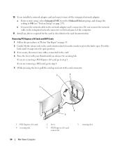
...change the setting to Off (see "System Setup" on the back panel of the card connector. 2 3 1 1 PCI Express x16 card 4 securing tab 54 Mini Tower Computer 4 5 2 lever 5 PCI Express x16 card connector 3 securing slot Removing PCI Express x16 Cards and DVI-Cards 1 Follow the procedures in the card documentation.... and want to turn off the integrated network adapter: a Enter system setup, select Integrated NIC from the inside to the network adapter card's connectors. 10 If you are removing a PCI Express x16 card, go to step 6 5 While pressing the lever, pull the card up and ...
...change the setting to Off (see "System Setup" on the back panel of the card connector. 2 3 1 1 PCI Express x16 card 4 securing tab 54 Mini Tower Computer 4 5 2 lever 5 PCI Express x16 card connector 3 securing slot Removing PCI Express x16 Cards and DVI-Cards 1 Follow the procedures in the card documentation.... and want to turn off the integrated network adapter: a Enter system setup, select Integrated NIC from the inside to the network adapter card's connectors. 10 If you are removing a PCI Express x16 card, go to step 6 5 While pressing the lever, pull the card up and ...
User's Guide
Page 55
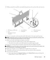
... cover from the Onboard Devices group, and change the setting to maintain FCC certification of the card connector. 2 3 4 1 5 7 6 1 PCI Express x16 DVI-card 4 lever 7 PCI Express x16 card connector 2 removal pull tab 5 securing slot 3 DVI-card connector 6 securing tab 7 If you are flush with the card for instructions. 12 If you close the card...
... cover from the Onboard Devices group, and change the setting to maintain FCC certification of the card connector. 2 3 4 1 5 7 6 1 PCI Express x16 DVI-card 4 lever 7 PCI Express x16 card connector 2 removal pull tab 5 securing slot 3 DVI-card connector 6 securing tab 7 If you are flush with the card for instructions. 12 If you close the card...
User's Guide
Page 58
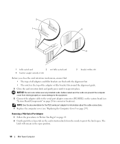
... installed cards. NOTICE: Do not route cables over the cards can prevent the computer cover from the inside to the serial port adapter connector (PS2/SER2) on the system board (see "Replacing the Computer Cover" on page 28 for information about the cable connections. 7 ... computer cover (see "System Board Components" on page 297). 2 1 3 4 1 fully seated card 2 4 bracket caught outside of slot not fully seated card 3 bracket within slot Before you close the card retention mechanism, ensure that: • The tops of the adapter or filler bracket fits around the alignment...
... installed cards. NOTICE: Do not route cables over the cards can prevent the computer cover from the inside to the serial port adapter connector (PS2/SER2) on the system board (see "Replacing the Computer Cover" on page 28 for information about the cable connections. 7 ... computer cover (see "System Board Components" on page 297). 2 1 3 4 1 fully seated card 2 4 bracket caught outside of slot not fully seated card 3 bracket within slot Before you close the card retention mechanism, ensure that: • The tops of the adapter or filler bracket fits around the alignment...


