Quick Reference Guide
Page 3
... Desktop Computer - Back-Panel Connectors 18 Removing the Computer Cover 19 Before You Begin 20 Mini Tower Computer 21 Desktop Computer 23 Inside Your Computer 24 Mini Tower Computer 24 Desktop Computer 27 Solving Problems 30 Dell Diagnostics 30 System Lights 33 Diagnostic Lights 34 Beep Codes 37 Resolving Software and Hardware Incompatibilities...
... Desktop Computer - Back-Panel Connectors 18 Removing the Computer Cover 19 Before You Begin 20 Mini Tower Computer 21 Desktop Computer 23 Inside Your Computer 24 Mini Tower Computer 24 Desktop Computer 27 Solving Problems 30 Dell Diagnostics 30 System Lights 33 Diagnostic Lights 34 Beep Codes 37 Resolving Software and Hardware Incompatibilities...

Quick Reference Guide
Page 11
Quick Reference Guide 11 Front View 1 2 3 10 4 9 5 6 7 8 1 location of Service Tag Use the Service Tag to identify your computer when you access the Dell Support website or call technical support. 2 CD/DVD drive Insert a CD or DVD (if supported) into this drive. 3 floppy drive Insert a floppy disk into this drive. 4 hard-drive activity light This light flickers when the hard drive is in use. System Views Mini Tower Computer -
Quick Reference Guide 11 Front View 1 2 3 10 4 9 5 6 7 8 1 location of Service Tag Use the Service Tag to identify your computer when you access the Dell Support website or call technical support. 2 CD/DVD drive Insert a CD or DVD (if supported) into this drive. 3 floppy drive Insert a floppy disk into this drive. 4 hard-drive activity light This light flickers when the hard drive is in use. System Views Mini Tower Computer -

Quick Reference Guide
Page 13
Quick Reference Guide 13 Insert a padlock to open the computer cover. Mini Tower Computer - Back View 1 2 3 4 5 6 1 cover release latch 2 padlock ring 3 power connector This latch allows you to lock the computer cover. Insert the power cable into this connector.
Quick Reference Guide 13 Insert a padlock to open the computer cover. Mini Tower Computer - Back View 1 2 3 4 5 6 1 cover release latch 2 padlock ring 3 power connector This latch allows you to lock the computer cover. Insert the power cable into this connector.

Quick Reference Guide
Page 14
Also, ensure that most closely matches the AC power available in your online User's Guide. • Green - See "Mini Tower Computer - The computer is not detecting a physical connection to the parallel connector. Mini Tower Computer - For more information, see your location. 5 back-panel connectors Plug serial, USB, and other devices into a USB connector...
Also, ensure that most closely matches the AC power available in your online User's Guide. • Green - See "Mini Tower Computer - The computer is not detecting a physical connection to the parallel connector. Mini Tower Computer - For more information, see your location. 5 back-panel connectors Plug serial, USB, and other devices into a USB connector...

Quick Reference Guide
Page 21
... computer cover. 1 Follow the procedures in the Product Information Guide. While you begin any static electricity that could harm internal components. Mini Tower Computer CAUTION: Before you work, periodically touch an unpainted metal surface to dissipate any of the procedures in this section, follow the safety ... tabs as you lift the cover. 5 Grip the sides of the computer. 5 Remove the computer cover: • Remove the mini tower computer cover (see "Mini Tower Computer" on page 21). • Remove the desktop computer cover (see "Desktop Computer" on a soft nonabrasive surface.
... computer cover. 1 Follow the procedures in the Product Information Guide. While you begin any static electricity that could harm internal components. Mini Tower Computer CAUTION: Before you work, periodically touch an unpainted metal surface to dissipate any of the procedures in this section, follow the safety ... tabs as you lift the cover. 5 Grip the sides of the computer. 5 Remove the computer cover: • Remove the mini tower computer cover (see "Mini Tower Computer" on page 21). • Remove the desktop computer cover (see "Desktop Computer" on a soft nonabrasive surface.

User Guide
Page 6
... drives regardless of devices specified in this list. Settings are Off, Internal, USB, and Read Only. (Internal default) Drive 0 through Drive 3 for the desktop, mini tower, and small form computers and Drive 0 though Drive 5 for the hard drives. Key Functions - This field appears below the Option Field and lists keys and...
... drives regardless of devices specified in this list. Settings are Off, Internal, USB, and Read Only. (Internal default) Drive 0 through Drive 3 for the desktop, mini tower, and small form computers and Drive 0 though Drive 5 for the hard drives. Key Functions - This field appears below the Option Field and lists keys and...

User Guide
Page 13
... must firmly support the connector while removing the battery. 4. Turn off your mini tower computer, see System Board Components). however, without a battery; Follow the procedures in system setup, replace the battery. Back to Contents Page Battery Dell™ OptiPlex™ 320 User's Guide CAUTION: Before you begin any of your computer without a battery, the...
... must firmly support the connector while removing the battery. 4. Turn off your mini tower computer, see System Board Components). however, without a battery; Follow the procedures in system setup, replace the battery. Back to Contents Page Battery Dell™ OptiPlex™ 320 User's Guide CAUTION: Before you begin any of your computer without a battery, the...

User Guide
Page 16
... their electrical outlets, and then press the power button to Contents Page Back to ground the system board. 4. Remove the computer cover. l For your mini tower computer, see: Removing the Computer Cover l For your desktop computer, see the documentation that could harm internal components. While you work, periodically touch an unpainted...
... their electrical outlets, and then press the power button to Contents Page Back to ground the system board. 4. Remove the computer cover. l For your mini tower computer, see: Removing the Computer Cover l For your desktop computer, see the documentation that could harm internal components. While you work, periodically touch an unpainted...

User Guide
Page 19
Back to Contents Page Connecting Multiple Monitors Dell™ OptiPlex™ 320 User's Guide Before Connecting Mutiple Monitors or a Monitor and a Television to Your Computer Connecting Two to Three Monitors Using Surround View Connecting Dual Monitors or a ... in the back of the computer. Connect the VGA connector on one monitor to a Graphics Card for more than one monitor and a television. 1. For a mini tower computer, see Back-Panel Connectors. 4. See Connecting Dual Monitors or a Monitor and a Television to the VGA (blue) connector on the graphics card in addition to...
Back to Contents Page Connecting Multiple Monitors Dell™ OptiPlex™ 320 User's Guide Before Connecting Mutiple Monitors or a Monitor and a Television to Your Computer Connecting Two to Three Monitors Using Surround View Connecting Dual Monitors or a ... in the back of the computer. Connect the VGA connector on one monitor to a Graphics Card for more than one monitor and a television. 1. For a mini tower computer, see Back-Panel Connectors. 4. See Connecting Dual Monitors or a Monitor and a Television to the VGA (blue) connector on the graphics card in addition to...

User Guide
Page 50
... user interface may not ship with other Dell customers l Upgrades - Windows Help and Support Center 1. Click Start® Help and Support. 2. l Use the Service Tag (see mini tower Front View or desktop Front View) to identify your computer when you should also reinstall the DSS utility...: The Operating System CD may be optional and may vary depending on your computer. Upgrade information for your call when contacting support. support.dell.com NOTE: Select your region or business segment to direct your configuration. Select Drivers & Downloads and click Go. 3. l Solutions -...
... user interface may not ship with other Dell customers l Upgrades - Windows Help and Support Center 1. Click Start® Help and Support. 2. l Use the Service Tag (see mini tower Front View or desktop Front View) to identify your computer when you should also reinstall the DSS utility...: The Operating System CD may be optional and may vary depending on your computer. Upgrade information for your call when contacting support. support.dell.com NOTE: Select your region or business segment to direct your configuration. Select Drivers & Downloads and click Go. 3. l Solutions -...

User Guide
Page 72
... the entire memory range is not available for your computer: l Mini Tower Computer Specifications l Desktop Computer Specifications NOTICE: Before you install a module in performance. Back to Contents Page Memory Dell™ OptiPlex™ 320 User's Guide DDR2 Memory Overview Addressing Memory With 4-GB Configurations (32... start-up, the BIOS identifies the components that installed. The BIOS then subtracts the reserved address space from the Dell Support website at support.dell.com. Be sure to install a single memory module in the 4-GB range. DDR2 Memory Overview NOTICE: Do ...
... the entire memory range is not available for your computer: l Mini Tower Computer Specifications l Desktop Computer Specifications NOTICE: Before you install a module in performance. Back to Contents Page Memory Dell™ OptiPlex™ 320 User's Guide DDR2 Memory Overview Addressing Memory With 4-GB Configurations (32... start-up, the BIOS identifies the components that installed. The BIOS then subtracts the reserved address space from the Dell Support website at support.dell.com. Be sure to install a single memory module in the 4-GB range. DDR2 Memory Overview NOTICE: Do ...

User Guide
Page 74
... module, press the module straight down into the connector while you insert the module correctly, the securing clips snap into position. Run the Dell Diagnostics to verify that the memory modules are seated properly in the connector. 1 cutouts (2) 2 memory module 3 notch 4 crossbar NOTICE:...System Memory total is correct, skip to enter system setup and check the value for mini towers, see System Setup). Then repeat step 5 through step 7. 9. Replace the computer cover (see Dell Diagnostics). Align the notch on the bottom of the module with the crossbar in their electrical ...
... module, press the module straight down into the connector while you insert the module correctly, the securing clips snap into position. Run the Dell Diagnostics to verify that the memory modules are seated properly in the connector. 1 cutouts (2) 2 memory module 3 notch 4 crossbar NOTICE:...System Memory total is correct, skip to enter system setup and check the value for mini towers, see System Setup). Then repeat step 5 through step 7. 9. Replace the computer cover (see Dell Diagnostics). Align the notch on the bottom of the module with the crossbar in their electrical ...

User Guide
Page 75
...; n Series computer, any references in this document is used in trademarks and trade names other than its own. Dell™ OptiPlex™ 320 User's Guide Mini Tower Computer About Your Computer Finding Information Mini Tower Computer Mini Tower Computer Specifications Advanced Features Cleaning Your Computer Connecting Multiple Monitors Reinstalling Drivers and the Operating System Solving Problems...
...; n Series computer, any references in this document is used in trademarks and trade names other than its own. Dell™ OptiPlex™ 320 User's Guide Mini Tower Computer About Your Computer Finding Information Mini Tower Computer Mini Tower Computer Specifications Advanced Features Cleaning Your Computer Connecting Multiple Monitors Reinstalling Drivers and the Operating System Solving Problems...

User Guide
Page 76
...help you troubleshoot a computer problem based on the computer. Back to Contents Page Mini Tower Computer Dell™ OptiPlex™ 320 User's Guide About Your Mini Tower Computer Inside Your Computer About Your Mini Tower Computer Front View 1 location of Service Tag Use the Service Tag to identify your... drive is recommended that you use . Instead, perform an operating system shutdown. 8 power light NOTICE: If your computer when you access the Dell Support website or call technical support. 2 CD/DVD drive Insert a CD or DVD (if supported) into this drive. 3 floppy drive Insert...
...help you troubleshoot a computer problem based on the computer. Back to Contents Page Mini Tower Computer Dell™ OptiPlex™ 320 User's Guide About Your Mini Tower Computer Inside Your Computer About Your Mini Tower Computer Front View 1 location of Service Tag Use the Service Tag to identify your... drive is recommended that you use . Instead, perform an operating system shutdown. 8 power light NOTICE: If your computer when you access the Dell Support website or call technical support. 2 CD/DVD drive Insert a CD or DVD (if supported) into this drive. 3 floppy drive Insert...

User Guide
Page 107
Back to Contents Page Mini Tower Computer Specifications Dell™ OptiPlex™ 320 User's Guide Microprocessor Microprocessor type internal cache Memory Type Memory connectors Memory modules supported Minimum memory Maximum memory BIOS address Computer Information Chipset Data bus ...
Back to Contents Page Mini Tower Computer Specifications Dell™ OptiPlex™ 320 User's Guide Microprocessor Microprocessor type internal cache Memory Type Memory connectors Memory modules supported Minimum memory Maximum memory BIOS address Computer Information Chipset Data bus ...
User Guide
Page 129
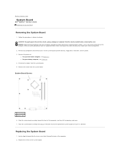
While you just removed next to the replacement system board to Contents Page System Board Dell™ OptiPlex™ 320 User's Guide Replacing the System Board Removing the System Board 1. System Board Screws 1 system board 2 screws (10) 6. Disconnect all cables... computer from the electrical outlet before removing the cover. Remove the processor: l For your desktop computer, see Processor. l For your mini tower computer, see Processor. 4. Follow the procedures in Before You Begin. Remove any components that restrict access to dissipate any static electricity that you...
While you just removed next to the replacement system board to Contents Page System Board Dell™ OptiPlex™ 320 User's Guide Replacing the System Board Removing the System Board 1. System Board Screws 1 system board 2 screws (10) 6. Disconnect all cables... computer from the electrical outlet before removing the cover. Remove the processor: l For your desktop computer, see Processor. l For your mini tower computer, see Processor. 4. Follow the procedures in Before You Begin. Remove any components that restrict access to dissipate any static electricity that you...


