
Quick Reference Guide
Page 27
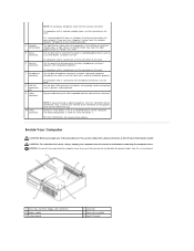
The real-time clock is being reset (jumpered temporarily). Password features are enabled (default setting). jumpered Desktop Computer unjumpered 2 1 3 4 6 5 1 drive bay (CD/DVD, floppy, 4 card slots and hard drive) 2 power supply 5 heat sink assembly 3 system board 6 front I/O panel Quick Reference Guide 27 Jumper PSWD Setting 1 RTCRST 1 Description Password features are disabled. The real-time clock has been enabled (default setting).
The real-time clock is being reset (jumpered temporarily). Password features are enabled (default setting). jumpered Desktop Computer unjumpered 2 1 3 4 6 5 1 drive bay (CD/DVD, floppy, 4 card slots and hard drive) 2 power supply 5 heat sink assembly 3 system board 6 front I/O panel Quick Reference Guide 27 Jumper PSWD Setting 1 RTCRST 1 Description Password features are disabled. The real-time clock has been enabled (default setting).

Quick Reference Guide
Page 33
... page 37. No corrective action is identified. Blinking green The computer is in your online User's Guide. Solid yellow The Dell Diagnostics is running , allow the testing to complete. Blinking yellow A power supply or system board failure has occurred. For instructions on diagnosing the beep code see "Beep Codes" on the system board...
... page 37. No corrective action is identified. Blinking green The computer is in your online User's Guide. Solid yellow The Dell Diagnostics is running , allow the testing to complete. Blinking yellow A power supply or system board failure has occurred. For instructions on diagnosing the beep code see "Beep Codes" on the system board...
User Guide
Page 23
... yellow when the computer is recommended that you do not accidentally disconnect cables from the system board. 1 drives bay (CD/DVD, floppy, and hard drive) 2 power supply 3 system board 4 card slots 5 heat sink assembly 6 front I/O panel Use the blue line-in connector It is transmitting or receiving network data. Use the back...
... yellow when the computer is recommended that you do not accidentally disconnect cables from the system board. 1 drives bay (CD/DVD, floppy, and hard drive) 2 power supply 3 system board 4 card slots 5 heat sink assembly 6 front I/O panel Use the blue line-in connector It is transmitting or receiving network data. Use the back...

User Guide
Page 40
... computer's electronic components. Lift the power supply up and out of the computer chassis. 1 release button 2 power supply 3 screws (2) 4 AC power connector 6. Replace the screws that attach the power supply to the back of the computer chassis. 4. Back to Contents Page Power Supply Dell™ OptiPlex™ 320 User's Guide Replacing the Power Supply DC Power Connectors Replacing the Power Supply CAUTION: Before you begin any of...
... computer's electronic components. Lift the power supply up and out of the computer chassis. 1 release button 2 power supply 3 screws (2) 4 AC power connector 6. Replace the screws that attach the power supply to the back of the computer chassis. 4. Back to Contents Page Power Supply Dell™ OptiPlex™ 320 User's Guide Replacing the Power Supply DC Power Connectors Replacing the Power Supply CAUTION: Before you begin any of...

User Guide
Page 47
... blinking light four lights on the front panel (see Diagnostic Lights) AUX_PWR on the system board Power DC power supply: Wattage Heat dissipation Voltage Backup battery 280 W 955 BTU/hr NOTE: Heat dissipation is calculated based upon the power supply wattage rating. 90 to 135 V at 60 Hz; 180 to 264 V at 50 Hz; 100...
... blinking light four lights on the front panel (see Diagnostic Lights) AUX_PWR on the system board Power DC power supply: Wattage Heat dissipation Voltage Backup battery 280 W 955 BTU/hr NOTE: Heat dissipation is calculated based upon the power supply wattage rating. 90 to 135 V at 60 Hz; 180 to 264 V at 50 Hz; 100...
User Guide
Page 70
...word wrap or formatting functionality (the option to operate with the monitor-for 2 hours. U UMA - uninterruptible power supply - Small UPS systems provide battery power for video cards and controllers that when combined with an integrated video controller) that can also be defined as... program that contain only text; A common type of virus is a boot virus, which is 1 ampere of characters. The measurement of electrical power. WHr - A connector used to attach a TV or digital audio device to video. trusted platform module - System memory dynamically allocated to the...
...word wrap or formatting functionality (the option to operate with the monitor-for 2 hours. U UMA - uninterruptible power supply - Small UPS systems provide battery power for video cards and controllers that when combined with an integrated video controller) that can also be defined as... program that contain only text; A common type of virus is a boot virus, which is 1 ampere of characters. The measurement of electrical power. WHr - A connector used to attach a TV or digital audio device to video. trusted platform module - System memory dynamically allocated to the...

User Guide
Page 75
...be used in any manner whatsoever without notice. © 2006 Dell Inc. Only) Removing and Replacing Parts Before You Begin Removing the Computer Cover I/O Panel Drives PCI and PCI Express Cards Power Supply Processor Battery System Board Memory Replacing the Computer Cover Notes, ...Bluetooth is a registered trademark of your computer. Information in trademarks and trade names other than its own. A00 Dell™ OptiPlex™ 320 User's Guide Mini Tower Computer About Your Computer Finding Information Mini Tower Computer Mini Tower Computer Specifications Advanced Features...
...be used in any manner whatsoever without notice. © 2006 Dell Inc. Only) Removing and Replacing Parts Before You Begin Removing the Computer Cover I/O Panel Drives PCI and PCI Express Cards Power Supply Processor Battery System Board Memory Replacing the Computer Cover Notes, ...Bluetooth is a registered trademark of your computer. Information in trademarks and trade names other than its own. A00 Dell™ OptiPlex™ 320 User's Guide Mini Tower Computer About Your Computer Finding Information Mini Tower Computer Mini Tower Computer Specifications Advanced Features...

User Guide
Page 79
CAUTION: To avoid electrical shock, always unplug your computer from the system board. 1 floppy drive 2 CD/DVD drive 3 power supply 4 system board 5 heat sink assembly 6 hard drive System Board Components 1 fan connector (FAN) 2 processor connector (CPU) 3 processor power connector (12VPOWER) 4 front-panel connector (FNT_PANEL) 5 memory module connectors (DIMM_1, DIMM_2) 10 internal buzzer (SPKR1) 11...
CAUTION: To avoid electrical shock, always unplug your computer from the system board. 1 floppy drive 2 CD/DVD drive 3 power supply 4 system board 5 heat sink assembly 6 hard drive System Board Components 1 fan connector (FAN) 2 processor connector (CPU) 3 processor power connector (12VPOWER) 4 front-panel connector (FNT_PANEL) 5 memory module connectors (DIMM_1, DIMM_2) 10 internal buzzer (SPKR1) 11...

User Guide
Page 102
... inside your computer's electronic components. You must route these cables properly when you touch any of the computer. 7. Back to Contents Page Power Supply Dell™ OptiPlex™ 320 User's Guide Replacing the Power Supply DC Power Connectors Replacing the Power Supply CAUTION: Before you remove them from the system board and drives. Remove the four screws that secure the...
... inside your computer's electronic components. You must route these cables properly when you touch any of the computer. 7. Back to Contents Page Power Supply Dell™ OptiPlex™ 320 User's Guide Replacing the Power Supply DC Power Connectors Replacing the Power Supply CAUTION: Before you remove them from the system board and drives. Remove the four screws that secure the...
User Guide
Page 103
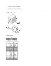
DC Power Connectors DC Power Connector P1 Pin Number Signal name 18-AWG Wire 1 +3.3 VDC Orange 2 +3.3 VDC Orange 3 GND Black 4 +5 VDC Red 5 GND Black 6 +5 VDC Red 7 GND Black 8 PS_PWRGOOD Gray 9 P5AUX Purple 10 +12 VDC White 11 +12 VDC White 12 +3.3 VDC Orange 13 +3.3 VDC Orange 14 -12 VDC Blue 15 GND Black 16 PWR_PS_ON Green 17 GND Black Replace the computer cover (see Replacing the Computer Cover). Connect the AC power cable to the power supply. 10. 9. Reconnect the DC power cables to the AC power connector. 11.
DC Power Connectors DC Power Connector P1 Pin Number Signal name 18-AWG Wire 1 +3.3 VDC Orange 2 +3.3 VDC Orange 3 GND Black 4 +5 VDC Red 5 GND Black 6 +5 VDC Red 7 GND Black 8 PS_PWRGOOD Gray 9 P5AUX Purple 10 +12 VDC White 11 +12 VDC White 12 +3.3 VDC Orange 13 +3.3 VDC Orange 14 -12 VDC Blue 15 GND Black 16 PWR_PS_ON Green 17 GND Black Replace the computer cover (see Replacing the Computer Cover). Connect the AC power cable to the power supply. 10. 9. Reconnect the DC power cables to the AC power connector. 11.

User Guide
Page 109
... integrated network adapter) Diagnostic lights Standby power light green light for 10-Mb operation and orange light for 100-Mb operation yellow blinking light four lights on the front panel (see Diagnostic Lights) AUX_PWR on the system board Power DC power supply: Wattage Heat dissipation Voltage Backup battery ...305 W 1041 BTU/hr NOTE: Heat dissipation is calculated based upon the power supply rating. 90 to 135 V at 60 Hz; 180 to 264 V at ...
... integrated network adapter) Diagnostic lights Standby power light green light for 10-Mb operation and orange light for 100-Mb operation yellow blinking light four lights on the front panel (see Diagnostic Lights) AUX_PWR on the system board Power DC power supply: Wattage Heat dissipation Voltage Backup battery ...305 W 1041 BTU/hr NOTE: Heat dissipation is calculated based upon the power supply rating. 90 to 135 V at 60 Hz; 180 to 264 V at ...

User Guide
Page 114
...proprietary interest in this product meets the ENERGY STAR guidelines for property damage, personal injury, or death. Dell™ OptiPlex™ 320 User's Guide Desktop Computer About Your Computer Finding Information Desktop Computer Desktop Computer Specifications Advanced Features Connecting Multiple ... Only) Removing and Replacing Parts Before You Begin Removing the Computer Cover I/O Panel Drives PCI and PCI Express Cards Power Supply Processor Battery System Board Memory Replacing the Computer Cover Notes, Notices, and Cautions NOTE: A NOTE indicates important information that...
...proprietary interest in this product meets the ENERGY STAR guidelines for property damage, personal injury, or death. Dell™ OptiPlex™ 320 User's Guide Desktop Computer About Your Computer Finding Information Desktop Computer Desktop Computer Specifications Advanced Features Connecting Multiple ... Only) Removing and Replacing Parts Before You Begin Removing the Computer Cover I/O Panel Drives PCI and PCI Express Cards Power Supply Processor Battery System Board Memory Replacing the Computer Cover Notes, Notices, and Cautions NOTE: A NOTE indicates important information that...

User Guide
Page 134
A power supply or system board failure has occurred. An integrated system board device may be off or green. If the Dell Diagnostics is in a normal "off" condition, or a possible pre-BIOS failure has occurred. Diagnostic Lights CAUTION: Before you begin any of ... installed, reinstall it , and then restart the computer. l If available, install properly working electrical outlet and press the power button. If the computer does not boot, contact Dell for technical assistance (see Diagnostic Lights). When the computer starts normally, the patterns or codes on the system board may...
A power supply or system board failure has occurred. An integrated system board device may be off or green. If the Dell Diagnostics is in a normal "off" condition, or a possible pre-BIOS failure has occurred. Diagnostic Lights CAUTION: Before you begin any of ... installed, reinstall it , and then restart the computer. l If available, install properly working electrical outlet and press the power button. If the computer does not boot, contact Dell for technical assistance (see Diagnostic Lights). When the computer starts normally, the patterns or codes on the system board may...


