Quick Reference Guide
Page 10
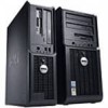
... must be set the switch to the voltage that your monitor and attached devices are electrically rated to 115-V. Mini Tower Computer - Back View 1 2 3 4 5 6 1 cover release latch 2 padlock ring 3 voltage selection switch This latch allows you to lock the computer cover. To avoid damaging a computer with a manual voltage-selection switch.
... must be set the switch to the voltage that your monitor and attached devices are electrically rated to 115-V. Mini Tower Computer - Back View 1 2 3 4 5 6 1 cover release latch 2 padlock ring 3 voltage selection switch This latch allows you to lock the computer cover. To avoid damaging a computer with a manual voltage-selection switch.
Quick Reference Guide
Page 14
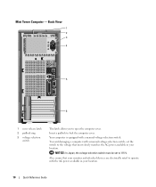
.... 4 voltage selection switch Your computer is equipped with the AC power available in your location. 5 padlock ring Insert a padlock to lock the computer cover. 6 cover release latch Use this latch to operate with a manual voltage-selection switch.
.... 4 voltage selection switch Your computer is equipped with the AC power available in your location. 5 padlock ring Insert a padlock to lock the computer cover. 6 cover release latch Use this latch to operate with a manual voltage-selection switch.
Quick Reference Guide
Page 17
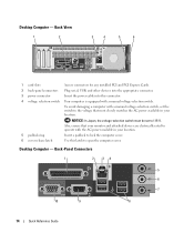
...components and cards with locking tabs; Mini Tower Computer CAUTION: Before you begin working inside your computer. Hold a card by its edges or by Dell is attached. NOTICE: When you begin any static electricity that both connectors are disconnecting this section, follow the safety instructions in "Before You Begin"... on page 16. 2 Lay the computer on its strain-relief loop, not on its side. 3 Slide the cover release latch back as the metal at the back of cable, press in on the locking tabs before you disconnect a cable, pull on its connector or...
...components and cards with locking tabs; Mini Tower Computer CAUTION: Before you begin working inside your computer. Hold a card by its edges or by Dell is attached. NOTICE: When you begin any static electricity that both connectors are disconnecting this section, follow the safety instructions in "Before You Begin"... on page 16. 2 Lay the computer on its strain-relief loop, not on its side. 3 Slide the cover release latch back as the metal at the back of cable, press in on the locking tabs before you disconnect a cable, pull on its connector or...
Quick Reference Guide
Page 18
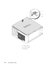
1 2 3 1 security cable slot 2 cover release latch 3 padlock ring 18 Quick Reference Guide
1 2 3 1 security cable slot 2 cover release latch 3 padlock ring 18 Quick Reference Guide
Quick Reference Guide
Page 19
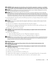
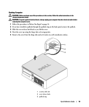
... electrical shock, always unplug your computer from the hinge tabs and set it aside on a soft nonabrasive surface. 1 2 3 1 security cable slot 2 cover release latch 3 padlock ring Quick Reference Guide 19 Desktop Computer CAUTION: Before you begin any of the procedures in this section, follow the safety instructions in..." on page 16. 2 If you have installed a padlock through the padlock ring on the back panel, remove the padlock. 3 Slide the cover release latch back as you lift the cover. 4 Pivot the cover up using the hinge tabs as leverage points. 5 Remove the cover from the electrical ...
... electrical shock, always unplug your computer from the hinge tabs and set it aside on a soft nonabrasive surface. 1 2 3 1 security cable slot 2 cover release latch 3 padlock ring Quick Reference Guide 19 Desktop Computer CAUTION: Before you begin any of the procedures in this section, follow the safety instructions in..." on page 16. 2 If you have installed a padlock through the padlock ring on the back panel, remove the padlock. 3 Slide the cover release latch back as you lift the cover. 4 Pivot the cover up using the hinge tabs as leverage points. 5 Remove the cover from the electrical ...


