Quick Reference Guide
Page 3
... Turning Off Your Computer 16 Mini Tower Computer 17 Desktop Computer 19 Inside Your Computer 20 Mini Tower Computer 20 Desktop Computer 23 Setting Up Your Computer 26 Solving Problems 28 Dell Diagnostics 28 System Lights 31 Diagnostic Lights 32 Beep Codes 35 Resolving Software and Hardware Incompatibilities 36 Using Microsoft Windows XP System Restore 36 Reinstalling Microsoft Windows XP 37 Using the Drivers and Utilities CD 40 Index 41 Contents 3 Back-Panel Connectors...
... Turning Off Your Computer 16 Mini Tower Computer 17 Desktop Computer 19 Inside Your Computer 20 Mini Tower Computer 20 Desktop Computer 23 Setting Up Your Computer 26 Solving Problems 28 Dell Diagnostics 28 System Lights 31 Diagnostic Lights 32 Beep Codes 35 Resolving Software and Hardware Incompatibilities 36 Using Microsoft Windows XP System Restore 36 Reinstalling Microsoft Windows XP 37 Using the Drivers and Utilities CD 40 Index 41 Contents 3 Back-Panel Connectors...
Quick Reference Guide
Page 5
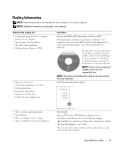
... updates can use the CD to your documentation. (see "Dell Diagnostics" on the optional Drivers and Utilities CD (ResourceCD). Quick Reference Guide 5 Dell™ Product Information Guide • How to remove and replace parts • Specifications • How to configure system settings • How to troubleshoot and solve problems User's Guide Microsoft® Windows® XP Help and Support Center 1 Click the Start button, then click Help and Support. 2 Click Dell User and System Guides, then click System Guides. 3 Click Dell Optiplex User's Guide...
... updates can use the CD to your documentation. (see "Dell Diagnostics" on the optional Drivers and Utilities CD (ResourceCD). Quick Reference Guide 5 Dell™ Product Information Guide • How to remove and replace parts • Specifications • How to configure system settings • How to troubleshoot and solve problems User's Guide Microsoft® Windows® XP Help and Support Center 1 Click the Start button, then click Help and Support. 2 Click Dell User and System Guides, then click System Guides. 3 Click Dell Optiplex User's Guide...
Quick Reference Guide
Page 6
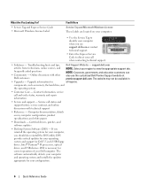
... Microsoft Windows License These labels are located on my computer configuration, product specifications, and white papers • Downloads - Upgrade information for correct operation of your computer. • Use the Service Tag to view the appropriate support site. Computer documentation, details on your Dell computer. DSS provides critical updates for your operating system and support for your configuration. 6 Quick Reference Guide Certified drivers, patches, and software updates • Desktop System Software (DSS...
... Microsoft Windows License These labels are located on my computer configuration, product specifications, and white papers • Downloads - Upgrade information for correct operation of your computer. • Use the Service Tag to view the appropriate support site. Computer documentation, details on your Dell computer. DSS provides critical updates for your operating system and support for your configuration. 6 Quick Reference Guide Certified drivers, patches, and software updates • Desktop System Software (DSS...
Quick Reference Guide
Page 7
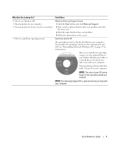
... Guide 7 Operating System CD The operating system is optional and may not ship with your problem. 4 Follow the instructions on page 37 for devices (such as a modem) • How to use the Operating System CD (see "Reinstalling Microsoft Windows XP" on the screen. What Are You Looking For? Find It Here • How to reinstall my operating system Windows Help and Support Center 1 Click the Start button...
... Guide 7 Operating System CD The operating system is optional and may not ship with your problem. 4 Follow the instructions on page 37 for devices (such as a modem) • How to use the Operating System CD (see "Reinstalling Microsoft Windows XP" on the screen. What Are You Looking For? Find It Here • How to reinstall my operating system Windows Help and Support Center 1 Click the Start button...
Quick Reference Guide
Page 9
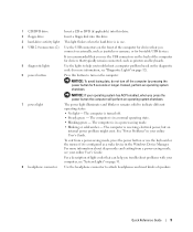
... USB devices. The computer is in your online User's Guide. NOTICE: To avoid losing data, do not turn on page 31. 8 headphone connector Use the headphone connector to indicate different operating states: • No light - To exit from a power-saving mode, see "System Lights" on the computer. The computer is in the Windows Device Manager. 1 CD/DVD drive Insert a CD or DVD (if applicable) into this drive. 2 floppy drive Insert a floppy disk...
... USB devices. The computer is in your online User's Guide. NOTICE: To avoid losing data, do not turn on page 31. 8 headphone connector Use the headphone connector to indicate different operating states: • No light - To exit from a power-saving mode, see "System Lights" on the computer. The computer is in the Windows Device Manager. 1 CD/DVD drive Insert a CD or DVD (if applicable) into this drive. 2 floppy drive Insert a floppy disk...
Quick Reference Guide
Page 10
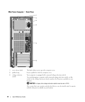
... a computer with the AC power available in your location. 10 Quick Reference Guide Insert a padlock to open the computer cover. Mini Tower Computer - Your computer is equipped with a manual voltage-selection switch. NOTICE: In Japan, the voltage-selection switch must be set the switch to the voltage that your monitor and attached devices are electrically rated to operate with a manual voltage-selection switch, set to 115-V.
... a computer with the AC power available in your location. 10 Quick Reference Guide Insert a padlock to open the computer cover. Mini Tower Computer - Your computer is equipped with a manual voltage-selection switch. NOTICE: In Japan, the voltage-selection switch must be set the switch to the voltage that your monitor and attached devices are electrically rated to operate with a manual voltage-selection switch, set to 115-V.
Quick Reference Guide
Page 11
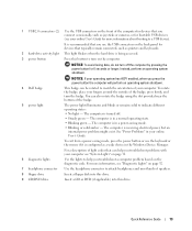
... must use the connector on the card. NOTE: The integrated parallel connector is not detecting a physical connection to the network. The computer is automatically disabled if the computer detects an installed card containing a parallel connector configured to the same address. A click indicates that you have a USB printer, plug it into a USB connector. NOTE: Do not plug a telephone cable into the appropriate connector. 6 card slots Access connectors for your online User's Guide. • Green - This light flashes...
... must use the connector on the card. NOTE: The integrated parallel connector is not detecting a physical connection to the network. The computer is automatically disabled if the computer detects an installed card containing a parallel connector configured to the same address. A click indicates that you have a USB printer, plug it into a USB connector. NOTE: Do not plug a telephone cable into the appropriate connector. 6 card slots Access connectors for your online User's Guide. • Green - This light flashes...
Quick Reference Guide
Page 13
... connect occasionally, such as printers and keyboards. 2 hard-drive activity light This light flickers when the hard drive is in a normal operating state. • Blinking green - The computer is recommended that you use the keyboard or the mouse if it is receiving electrical power, but an internal power problem might exist. The computer is being accessed. 3 power button Press this drive. For more information about booting to a USB device). 1 USB 2.0 connectors (2) Use the USB connectors on page 32. 7 headphone connector Use...
... connect occasionally, such as printers and keyboards. 2 hard-drive activity light This light flickers when the hard drive is in a normal operating state. • Blinking green - The computer is recommended that you use the keyboard or the mouse if it is receiving electrical power, but an internal power problem might exist. The computer is being accessed. 3 power button Press this drive. For more information about booting to a USB device). 1 USB 2.0 connectors (2) Use the USB connectors on page 32. 7 headphone connector Use...
Quick Reference Guide
Page 14
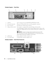
... to lock the computer cover. 6 cover release latch Use this connector. 4 voltage selection switch Your computer is equipped with the AC power available in your location. Desktop Computer - Back View 1 2 3 4 5 6 1 card slots Access connectors for any installed PCI and PCI Express Cards. 2 back-panel connectors Plug serial, USB, and other devices into the appropriate connector. 3 power connector Insert the power cable into this latch to 115-V. To avoid damaging a computer with a manual voltage-selection switch, set to open the computer cover. Desktop Computer -
... to lock the computer cover. 6 cover release latch Use this connector. 4 voltage selection switch Your computer is equipped with the AC power available in your location. Desktop Computer - Back View 1 2 3 4 5 6 1 card slots Access connectors for any installed PCI and PCI Express Cards. 2 back-panel connectors Plug serial, USB, and other devices into the appropriate connector. 3 power connector Insert the power cable into this latch to 115-V. To avoid damaging a computer with a manual voltage-selection switch, set to open the computer cover. Desktop Computer -

Quick Reference Guide
Page 15
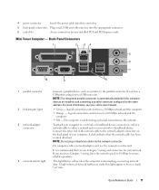
... integrated parallel connector is automatically disabled if the computer detects an installed card containing a parallel connector configured to the network. A click indicates that you use Category 3 wiring, force the network speed to 10 Mbps to ensure reliable operation. On computers with a network adapter card, use the connector on the card. If you have a USB printer, plug it into a USB connector. This light flashes yellow when the computer is on the back panel of a network cable to attach...
... integrated parallel connector is automatically disabled if the computer detects an installed card containing a parallel connector configured to the network. A click indicates that you use Category 3 wiring, force the network speed to 10 Mbps to ensure reliable operation. On computers with a network adapter card, use the connector on the card. If you have a USB printer, plug it into a USB connector. This light flashes yellow when the computer is on the back panel of a network cable to attach...
Quick Reference Guide
Page 16
... Guide. 16 Quick Reference Guide 8 USB 2.0 connectors (4) 9 video connector 10 serial connector Use the back USB connectors for devices that typically remain connected, such as a handheld device, to the serial port. NOTE: If you shut down the operating system: a Save and close any open files and exit any open programs before you purchased an optional graphics card, this section, follow the safety instructions in your operating system, turn off when you are turned off. Removing the Computer Cover...
... Guide. 16 Quick Reference Guide 8 USB 2.0 connectors (4) 9 video connector 10 serial connector Use the back USB connectors for devices that typically remain connected, such as a handheld device, to the serial port. NOTE: If you shut down the operating system: a Save and close any open files and exit any open programs before you purchased an optional graphics card, this section, follow the safety instructions in your operating system, turn off when you are turned off. Removing the Computer Cover...
Quick Reference Guide
Page 17
... the cable. Hold a card by its edges or by Dell is attached. NOTICE: Only a certified service technician should perform repairs on a soft nonabrasive surface. Damage due to dissipate any telephone or telecommunication lines from the electrical outlet before you work, periodically touch an unpainted metal surface to servicing that both connectors are disconnecting this section, follow the safety instructions...
... the cable. Hold a card by its edges or by Dell is attached. NOTICE: Only a certified service technician should perform repairs on a soft nonabrasive surface. Damage due to dissipate any telephone or telecommunication lines from the electrical outlet before you work, periodically touch an unpainted metal surface to servicing that both connectors are disconnecting this section, follow the safety instructions...
Quick Reference Guide
Page 25
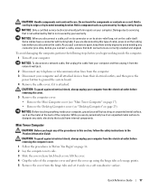
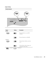
The real-time clock has not been reset. unjumpered Quick Reference Guide 25 Jumper Settings Desktop Computer PSWD RTCRST Jumper PSWD 1 2 3 Setting Description Password features are disabled. jumpered The real-time clock is being reset (jumpered temporarily). RTCRST 3 2 1 Password features are enabled (default).
The real-time clock has not been reset. unjumpered Quick Reference Guide 25 Jumper Settings Desktop Computer PSWD RTCRST Jumper PSWD 1 2 3 Setting Description Password features are disabled. jumpered The real-time clock is being reset (jumpered temporarily). RTCRST 3 2 1 Password features are enabled (default).

Quick Reference Guide
Page 26
... follow the safety instructions in Product Information Guide. NOTICE: Do not attempt to the network adapter 2 Connect the modem or network cable. Align and gently insert the monitor cable to the modem. 3 Connect the monitor. NOTE: Before you have the video connector underneath the back of the procedures in your computer. NOTICE: To avoid damaging a computer with a manual voltage-selection switch, set the switch to the voltage...
... follow the safety instructions in Product Information Guide. NOTICE: Do not attempt to the network adapter 2 Connect the modem or network cable. Align and gently insert the monitor cable to the modem. 3 Connect the monitor. NOTE: Before you have the video connector underneath the back of the procedures in your computer. NOTICE: To avoid damaging a computer with a manual voltage-selection switch, set the switch to the voltage...

Quick Reference Guide
Page 30
... your part. Performs a thorough check of each test screen. You can customize the test by changing the test settings. 4 When the tests are completed, if you are running the test. NOTE: The Service Tag for all devices attached to select a test based on your hardware configuration for running the Dell Diagnostics from system setup, memory, and various internal tests, and it displays the information in the device list in the following table for the option you...
... your part. Performs a thorough check of each test screen. You can customize the test by changing the test settings. 4 When the tests are completed, if you are running the test. NOTE: The Service Tag for all devices attached to select a test based on your hardware configuration for running the Dell Diagnostics from system setup, memory, and various internal tests, and it displays the information in the device list in the following table for the option you...
Quick Reference Guide
Page 31
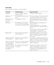
... incorrectly installed. Press the power button, move the mouse, or press a key on page 32). Blinking yellow A power supply or system board failure has occurred. If the problem is identified. If the computer does not boot, contact Dell for technical assistance. see your online User's Guide. Solid green and a beep A problem was detected while the code during POST Solid green power light and no be faulty. Solid green power light, The monitor or the graphics card...
... incorrectly installed. Press the power button, move the mouse, or press a key on page 32). Blinking yellow A power supply or system board failure has occurred. If the problem is identified. If the computer does not boot, contact Dell for technical assistance. see your online User's Guide. Solid green and a beep A problem was detected while the code during POST Solid green power light and no be faulty. Solid green power light, The monitor or the graphics card...
Quick Reference Guide
Page 34
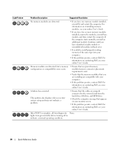
...; Verify that the memory modules that appears on contacting Dell, see your online User's Guide. • If you have two or more memory modules installed, remove the modules, reinstall one memory module installed, reinstall it and restart the computer. For information on your online User's Guide. A failure has occurred. lights turn green briefly before turning off to the system board from the hard drive, CD drive, and DVD drive. • Check...
...; Verify that the memory modules that appears on contacting Dell, see your online User's Guide. • If you have two or more memory modules installed, remove the modules, reinstall one memory module installed, reinstall it and restart the computer. For information on your online User's Guide. A failure has occurred. lights turn green briefly before turning off to the system board from the hard drive, CD drive, and DVD drive. • Check...
Quick Reference Guide
Page 37
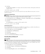
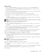
... written for the Windows default view in Windows XP Home Edition, so the steps will differ if you reinstall Windows XP with a newly installed driver, first try using Windows XP Professional. To verify that System Restore is enabled: 1 Click the Start button and click Control Panel. 2 Click Performance and Maintenance. 3 Click System. 4 Click the System Restore tab. 5 Ensure that Turn off System Restore is automatically disabled. 5 Click Next. Undoing...
... written for the Windows default view in Windows XP Home Edition, so the steps will differ if you reinstall Windows XP with a newly installed driver, first try using Windows XP Professional. To verify that System Restore is enabled: 1 Click the Start button and click Control Panel. 2 Click Performance and Maintenance. 3 Click System. 4 Click the System Restore tab. 5 Ensure that Turn off System Restore is automatically disabled. 5 Click Next. Undoing...
Quick Reference Guide
Page 39
... Windows XP installed and you want to install a new copy of Windows XP, press to select that option. 5 Press to select the highlighted partition (recommended), and follow the instructions on the size of the hard drive and the speed of your current Windows XP data, type r to select the repair option, and remove the CD. 4 If you want to recover your settings, accept the default selections. Windows XP installs the operating...
... Windows XP installed and you want to install a new copy of Windows XP, press to select that option. 5 Press to select the highlighted partition (recommended), and follow the instructions on the size of the hard drive and the speed of your current Windows XP data, type r to select the repair option, and remove the CD. 4 If you want to recover your settings, accept the default selections. Windows XP installs the operating...
Quick Reference Guide
Page 42
R reinstalling Drivers and Utilties CD, 5 ResourceCD, 5 Windows XP, 37 S safety instructions, 5 Service Tag, 6 software conflicts, 36 system board, 21, 24 System Restore, 36 Windows XP Hardware Troubleshooter, 36 Help and Support Center, 7 reinstalling, 37 setup, 39 System Restore, 36 T troubleshooting beep codes, 35 conflicts, 36 Dell Diagnostics, 28 diagnostic lights, 32 Hardware Troubleshooter, 36 Help and Support Center, 7 restore computer to previous operating state, 36 system lights, 31 U User's Guide, 5 W warranty, 5 42 Index
R reinstalling Drivers and Utilties CD, 5 ResourceCD, 5 Windows XP, 37 S safety instructions, 5 Service Tag, 6 software conflicts, 36 system board, 21, 24 System Restore, 36 Windows XP Hardware Troubleshooter, 36 Help and Support Center, 7 reinstalling, 37 setup, 39 System Restore, 36 T troubleshooting beep codes, 35 conflicts, 36 Dell Diagnostics, 28 diagnostic lights, 32 Hardware Troubleshooter, 36 Help and Support Center, 7 restore computer to previous operating state, 36 system lights, 31 U User's Guide, 5 W warranty, 5 42 Index


