Quick Reference Guide
Page 3
...- Front View 12 Desktop Computer - Back View 14 Desktop Computer - Front View 8 Mini Tower Computer - Back-Panel Connectors 14 Removing the Computer Cover 16 Before You Begin 16 Turning Off Your Computer 16 Mini Tower Computer 17 Desktop Computer 19 Inside Your Computer 20 Mini Tower Computer... 20 Desktop Computer 23 Setting Up Your Computer 26 Solving Problems 28 Dell Diagnostics 28 System Lights 31 Diagnostic Lights...
...- Front View 12 Desktop Computer - Back View 14 Desktop Computer - Front View 8 Mini Tower Computer - Back-Panel Connectors 14 Removing the Computer Cover 16 Before You Begin 16 Turning Off Your Computer 16 Mini Tower Computer 17 Desktop Computer 19 Inside Your Computer 20 Mini Tower Computer... 20 Desktop Computer 23 Setting Up Your Computer 26 Solving Problems 28 Dell Diagnostics 28 System Lights 31 Diagnostic Lights...
Quick Reference Guide
Page 12
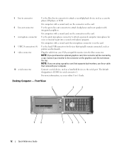
Do not remove the cap. Connect a serial device, such as a cassette player, CD player, or VCR. NOTE: If you are using a graphics card that supports dual monitors, use ... attach a personal computer microphone for voice or musical input into the blue connector. NOTE: If you purchased an optional graphics card, this connector will be covered by a cap. Desktop Computer - 5 line-in connector 6 line-out connector 7 microphone connector 8 USB 2.0 connectors (4) 9 video connector 10 serial connector Use the blue line-in connector...
Do not remove the cap. Connect a serial device, such as a cassette player, CD player, or VCR. NOTE: If you are using a graphics card that supports dual monitors, use ... attach a personal computer microphone for voice or musical input into the blue connector. NOTE: If you purchased an optional graphics card, this connector will be covered by a cap. Desktop Computer - 5 line-in connector 6 line-out connector 7 microphone connector 8 USB 2.0 connectors (4) 9 video connector 10 serial connector Use the blue line-in connector...
Quick Reference Guide
Page 16
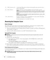
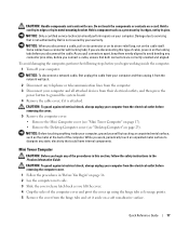
... and any of the procedures in this connector will be covered by a cap. Removing the Computer Cover Before You Begin This chapter provides procedures for removing and installing the components in the Product Information Guide. 16... Quick Reference Guide b In the Turn off computer window, click Turn off . Before Working Inside Your Computer Use the following conditions exist: • You have performed the steps in your Dell...
... and any of the procedures in this connector will be covered by a cap. Removing the Computer Cover Before You Begin This chapter provides procedures for removing and installing the components in the Product Information Guide. 16... Quick Reference Guide b In the Turn off computer window, click Turn off . Before Working Inside Your Computer Use the following conditions exist: • You have performed the steps in your Dell...
Quick Reference Guide
Page 17
...unplug your computer and all attached devices from the electrical outlet before removing the cover. 5 Remove the computer cover: • Remove the Mini Computer cover (see "Mini Tower Computer" on page 17). • Remove the Desktop Computer cover (see "Desktop Computer" on the locking tabs before you disconnect the... Only a certified service technician should perform repairs on a card. While you connect a cable, ensure that is not authorized by Dell is attached. NOTICE: To disconnect a network cable, first unplug the cable from your computer and then unplug it from the electrical ...
...unplug your computer and all attached devices from the electrical outlet before removing the cover. 5 Remove the computer cover: • Remove the Mini Computer cover (see "Mini Tower Computer" on page 17). • Remove the Desktop Computer cover (see "Desktop Computer" on the locking tabs before you disconnect the... Only a certified service technician should perform repairs on a card. While you connect a cable, ensure that is not authorized by Dell is attached. NOTICE: To disconnect a network cable, first unplug the cable from your computer and then unplug it from the electrical ...
Quick Reference Guide
Page 19
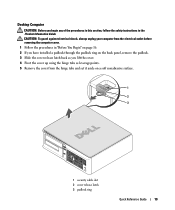
... the hinge tabs and set it aside on the back panel, remove the padlock. 3 Slide the cover release latch back as you lift the cover. 4 Pivot the cover up using the hinge tabs as leverage points. 5 Remove the cover from the electrical outlet before removing the computer cover. 1 Follow the procedures in the Product Information Guide. Desktop Computer...
... the hinge tabs and set it aside on the back panel, remove the padlock. 3 Slide the cover release latch back as you lift the cover. 4 Pivot the cover up using the hinge tabs as leverage points. 5 Remove the cover from the electrical outlet before removing the computer cover. 1 Follow the procedures in the Product Information Guide. Desktop Computer...
Quick Reference Guide
Page 20
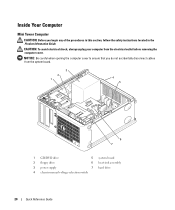
... Reference Guide Inside Your Computer Mini Tower Computer CAUTION: Before you do not accidentally disconnect cables from the electrical outlet before removing the computer cover. NOTICE: Be careful when opening the computer cover to ensure that you begin any of the procedures in this section, follow the safety instructions located in the Product...
... Reference Guide Inside Your Computer Mini Tower Computer CAUTION: Before you do not accidentally disconnect cables from the electrical outlet before removing the computer cover. NOTICE: Be careful when opening the computer cover to ensure that you begin any of the procedures in this section, follow the safety instructions located in the Product...

Quick Reference Guide
Page 23
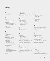
NOTICE: Be careful when opening the computer cover to ensure that you begin any of the procedures in this section, follow the safety instructions in the Product Information Guide. CAUTION: To avoid electrical shock, always unplug your computer from the system board. 2 1 3 4 6 5 1 drive bay (CD/DVD, floppy, 4 card slots and hard drive) 2 power supply 5 heat sink assembly 3 system board 6 front I/O panel Quick Reference Guide 23 Desktop Computer CAUTION: Before you do not accidentally disconnect cables from the electrical outlet before removing the computer cover.
NOTICE: Be careful when opening the computer cover to ensure that you begin any of the procedures in this section, follow the safety instructions in the Product Information Guide. CAUTION: To avoid electrical shock, always unplug your computer from the system board. 2 1 3 4 6 5 1 drive bay (CD/DVD, floppy, 4 card slots and hard drive) 2 power supply 5 heat sink assembly 3 system board 6 front I/O panel Quick Reference Guide 23 Desktop Computer CAUTION: Before you do not accidentally disconnect cables from the electrical outlet before removing the computer cover.
Quick Reference Guide
Page 41
Index B beep codes, 35 C CD operating system, 7 conflicts software and hardware incompatibilities, 36 cover removing, 16 D Dell support site, 6 Dell Diagnostics, 28 Dell Premier Support website, 5-6 diagnostics beep codes, 35 Dell Diagnostics, 28 Drivers and Utilities CD, 5 documentation device, 5 online, 6 ResourceCD, 5 System Information ... codes, 35 diagnostic lights, 32 system lights, 31 F Finding Information, 5 H hardware beep codes, 35 conflicts, 36 Dell Diagnostics, 28 Hardware Troubleshooter, 36 Help and Support Center, 7 I installing parts before you begin, 16 turning off your computer...
Index B beep codes, 35 C CD operating system, 7 conflicts software and hardware incompatibilities, 36 cover removing, 16 D Dell support site, 6 Dell Diagnostics, 28 Dell Premier Support website, 5-6 diagnostics beep codes, 35 Dell Diagnostics, 28 Drivers and Utilities CD, 5 documentation device, 5 online, 6 ResourceCD, 5 System Information ... codes, 35 diagnostic lights, 32 system lights, 31 F Finding Information, 5 H hardware beep codes, 35 conflicts, 36 Dell Diagnostics, 28 Hardware Troubleshooter, 36 Help and Support Center, 7 I installing parts before you begin, 16 turning off your computer...


