
Service Manual
Page 3
DellTM XFR D630 Fully Rugged Notebook Service Manual Table of Contents 1 BEFORE YOU BEGIN ...6 1.1 RECOMMENDED TOOLS ...6 1.2 TURNING OFF YOUR COMPUTER 6 1.3 BEFORE WORKING INSIDE YOUR COMPUTER 6 1.4 SCREW CHART ...8 2 XBAY ... 4.1 REPLACING THE STYLUS CLIP 17 4.2 REPLACING THE STYLUS 19 5 HANDLE...19 5.1 REMOVING THE HANDLE 20 5.2 INSTALLING THE HANDLE 20 6 PORT COVERS ...21 6.1 COMMS DOOR ...21 6.2 DOCKING DOOR ...22 6.3 VGA DOOR...25 6.4 POWER DOOR ...28 6.5 XBAY DOOR ...29 6.6 AUDIO PORTS/WIFI DOOR 31 6.7 USB SIDE DOOR ...32 6.8 USB REAR DOOR ...34 6.9 PC...
DellTM XFR D630 Fully Rugged Notebook Service Manual Table of Contents 1 BEFORE YOU BEGIN ...6 1.1 RECOMMENDED TOOLS ...6 1.2 TURNING OFF YOUR COMPUTER 6 1.3 BEFORE WORKING INSIDE YOUR COMPUTER 6 1.4 SCREW CHART ...8 2 XBAY ... 4.1 REPLACING THE STYLUS CLIP 17 4.2 REPLACING THE STYLUS 19 5 HANDLE...19 5.1 REMOVING THE HANDLE 20 5.2 INSTALLING THE HANDLE 20 6 PORT COVERS ...21 6.1 COMMS DOOR ...21 6.2 DOCKING DOOR ...22 6.3 VGA DOOR...25 6.4 POWER DOOR ...28 6.5 XBAY DOOR ...29 6.6 AUDIO PORTS/WIFI DOOR 31 6.7 USB SIDE DOOR ...32 6.8 USB REAR DOOR ...34 6.9 PC...

Service Manual
Page 10
DellTM XFR D630 Fully Rugged Notebook Service Manual 18806 18810 18804 18807 18811 18623 18424 18043 18425 18043 18044 18426 18806 18808 18812 18802 18618 AV DOOR ASSY HDD DOOR ASSY FAN COVER BATTERY DOOR ASSY DOCKING DOOR ASSY KEYBOARD ASSY CSK SCREW M3 X 10 -BLACK ASSY HANDLE WITH HOLDER CSK SCREW M2 X 10 -BLACK ASSY HANDLE WITH HOLDER ASSY HANDLE CSK SCREW M2 X 3 -BLACK AV DOOR ASSY VGA DOOR ASSY DVD DOOR ASSY PALMREST ASSY AV DOOR COVER ASSY 4 2 4 2 6 4 4 4 4 2 2 2 2 10 2 2 2 18427 CSK SCREW M2.5 X 6 -BLACK 3 Page 10 of 106 Revision A01
DellTM XFR D630 Fully Rugged Notebook Service Manual 18806 18810 18804 18807 18811 18623 18424 18043 18425 18043 18044 18426 18806 18808 18812 18802 18618 AV DOOR ASSY HDD DOOR ASSY FAN COVER BATTERY DOOR ASSY DOCKING DOOR ASSY KEYBOARD ASSY CSK SCREW M3 X 10 -BLACK ASSY HANDLE WITH HOLDER CSK SCREW M2 X 10 -BLACK ASSY HANDLE WITH HOLDER ASSY HANDLE CSK SCREW M2 X 3 -BLACK AV DOOR ASSY VGA DOOR ASSY DVD DOOR ASSY PALMREST ASSY AV DOOR COVER ASSY 4 2 4 2 6 4 4 4 4 2 2 2 2 10 2 2 2 18427 CSK SCREW M2.5 X 6 -BLACK 3 Page 10 of 106 Revision A01

Service Manual
Page 13
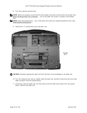
DellTM XFR D630 Fully Rugged Notebook Service Manual 18815 XFR LCD ASSY TOUCH SCREEN 8 18802 PALMREST ASSY 2 18803 CARD CAGE ON BASE CHASSIS 4 18623 KEYBOARD ASSY 3 18823 MOTHERBOARD ASSY 2 18591 18802 PAN HEAD SCREW M2.... or placing heavy objects on the taskbar, click the device you can remove and install devices while the computer is not present, you want to a docking device (docked). 1. Page 13 of them in a safe, dry place when they are not installed in the computer. If present, remove the device locking screw from...
DellTM XFR D630 Fully Rugged Notebook Service Manual 18815 XFR LCD ASSY TOUCH SCREEN 8 18802 PALMREST ASSY 2 18803 CARD CAGE ON BASE CHASSIS 4 18623 KEYBOARD ASSY 3 18823 MOTHERBOARD ASSY 2 18591 18802 PAN HEAD SCREW M2.... or placing heavy objects on the taskbar, click the device you can remove and install devices while the computer is not present, you want to a docking device (docked). 1. Page 13 of them in a safe, dry place when they are not installed in the computer. If present, remove the device locking screw from...

Service Manual
Page 22
Remove the 6 screws that secure the Docking Door to the notebook. 6.2 Docking Door The Docking Door is located on the notebook. 2. Align the Comms Door with the Comms Door mounting holes on the bottom of 106 Revision A01 Use the 2 screws to secure the Comms Door to the notebook. Page 22 of the notebook, and protects the docking connector. 6.2.1 Removing the Docking Door 1. DellTM XFR D630 Fully Rugged Notebook Service Manual 6.1.2 Installing the Comms Door 1.
Remove the 6 screws that secure the Docking Door to the notebook. 6.2 Docking Door The Docking Door is located on the notebook. 2. Align the Comms Door with the Comms Door mounting holes on the bottom of 106 Revision A01 Use the 2 screws to secure the Comms Door to the notebook. Page 22 of the notebook, and protects the docking connector. 6.2.1 Removing the Docking Door 1. DellTM XFR D630 Fully Rugged Notebook Service Manual 6.1.2 Installing the Comms Door 1.
Service Manual
Page 23
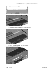
Page 23 of 106 Revision A01 Remove the 2 brackets that secure the Docking Door. 3. DellTM XFR D630 Fully Rugged Notebook Service Manual 2. Lift the Docking Door away from the notebook.
Page 23 of 106 Revision A01 Remove the 2 brackets that secure the Docking Door. 3. DellTM XFR D630 Fully Rugged Notebook Service Manual 2. Lift the Docking Door away from the notebook.
Service Manual
Page 24
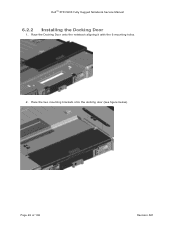
Place the Docking Door onto the notebook aligning it with the 6 mounting holes. 2. Place the two mounting brackets onto the docking door (see figure below). Page 24 of 106 Revision A01 DellTM XFR D630 Fully Rugged Notebook Service Manual 6.2.2 Installing the Docking Door 1.
Place the Docking Door onto the notebook aligning it with the 6 mounting holes. 2. Place the two mounting brackets onto the docking door (see figure below). Page 24 of 106 Revision A01 DellTM XFR D630 Fully Rugged Notebook Service Manual 6.2.2 Installing the Docking Door 1.
Service Manual
Page 25
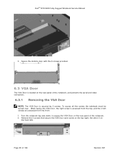
... by 3 screws. Secure the docking door with the 6 screws provided. 6.3 VGA Door The VGA Door is accessed from the top, and the 2 left ). Remove the 3 screws that secure the VGA Door (one screw on the top right, the other 2 on the rear panel of the notebook. 2. DellTM XFR D630 Fully Rugged Notebook Service...
... by 3 screws. Secure the docking door with the 6 screws provided. 6.3 VGA Door The VGA Door is accessed from the top, and the 2 left ). Remove the 3 screws that secure the VGA Door (one screw on the top right, the other 2 on the rear panel of the notebook. 2. DellTM XFR D630 Fully Rugged Notebook Service...
Service Manual
Page 79
...of 106 Revision A01 Page 79 of the palm rest screws is located in the battery 170H bay. DellTM XFR D630 Fully Rugged Notebook Service Manual 8. Continue to the palm rest. 10. Remove the palm rest. Remove the ... to raise the palm rest, and then disconnect the USB control cable from the system board. 11. NOTE: Open the Docking Door. Turn the computer top-side up, slightly raise the palm rest, and then disconnect the touch-pad cable connector from... upside-down. Screws (11) NOTICE: Carefully separate the palm rest from the system (see Removing the Docking Door.) 17H 9.
...of 106 Revision A01 Page 79 of the palm rest screws is located in the battery 170H bay. DellTM XFR D630 Fully Rugged Notebook Service Manual 8. Continue to the palm rest. 10. Remove the palm rest. Remove the ... to raise the palm rest, and then disconnect the USB control cable from the system board. 11. NOTE: Open the Docking Door. Turn the computer top-side up, slightly raise the palm rest, and then disconnect the touch-pad cable connector from... upside-down. Screws (11) NOTICE: Carefully separate the palm rest from the system (see Removing the Docking Door.) 17H 9.

User Guide
Page 8
... Icon 106 Double-Clicking the Dell Support Icon 106 Drive Problems 106 Media drive problems 107 If you cannot eject the CD, CD-RW, DVD, or DVD+RW drive tray 107 ... Area Network (WLAN 120 Mobile Broadband (Wireless Wide Area Network 120 PC Card Problems 121 Power Problems 122 Ensuring Sufficient Power for Your Computer 123 Docking Power Considerations 123 8
... Icon 106 Double-Clicking the Dell Support Icon 106 Drive Problems 106 Media drive problems 107 If you cannot eject the CD, CD-RW, DVD, or DVD+RW drive tray 107 ... Area Network (WLAN 120 Mobile Broadband (Wireless Wide Area Network 120 PC Card Problems 121 Power Problems 122 Ensuring Sufficient Power for Your Computer 123 Docking Power Considerations 123 8
User Guide
Page 32
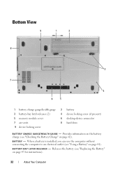
...). Bottom View 9 1 2 8 3 7 4 6 5 1 battery charge gauge/health gauge 3 battery-bay latch releases (2) 5 memory module cover 7 air vents 9 device locking screw 2 battery 4 device locking screw (if present) 6 docking-device connector 8 hard drive B A T T E R Y C H A R G E G A U G E / H E A L T H G A U G E - Provides information on the battery charge (see "Checking the Battery Charge" on page 47 for instructions). 32 About Your Computer...
...). Bottom View 9 1 2 8 3 7 4 6 5 1 battery charge gauge/health gauge 3 battery-bay latch releases (2) 5 memory module cover 7 air vents 9 device locking screw 2 battery 4 device locking screw (if present) 6 docking-device connector 8 hard drive B A T T E R Y C H A R G E G A U G E / H E A L T H G A U G E - Provides information on the battery charge (see "Checking the Battery Charge" on page 47 for instructions). 32 About Your Computer...
User Guide
Page 33
The computer uses an internal fan to a docking device. D O C K I C E C O N N E C T O R - See the Dell documentation that contains the second memory module connector (DIMM B) (see "Memory" on page 157) AI R VE N T S - If present, locks devices, such as an optical drive, in place. D E V I N G - M EM O R Y M O D U L E C O V E R - Lets you attach your docking device for more information. D E V I C E L O C K I N G S C R E W - Covers the compartment that came...
The computer uses an internal fan to a docking device. D O C K I C E C O N N E C T O R - See the Dell documentation that contains the second memory module connector (DIMM B) (see "Memory" on page 157) AI R VE N T S - If present, locks devices, such as an optical drive, in place. D E V I N G - M EM O R Y M O D U L E C O V E R - Lets you attach your docking device for more information. D E V I C E L O C K I N G S C R E W - Covers the compartment that came...
User Guide
Page 47
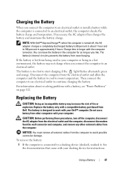
NOTE: With Dell™ ExpressCharge™, when the computer is connected to a docking device (docked), undock it. Then connect the computer to an electrical outlet to continue... connected to an electrical outlet, the computer checks the battery charge and temperature. Do not use a battery from Dell. Using a Battery 47 See the documentation that came with the computer turned on page 122. Replace the battery ... install a battery while the computer is designed to work with your Dell™ computer. The battery is longer with your docking device for as long as you like.
NOTE: With Dell™ ExpressCharge™, when the computer is connected to a docking device (docked), undock it. Then connect the computer to an electrical outlet to continue... connected to an electrical outlet, the computer checks the battery charge and temperature. Do not use a battery from Dell. Using a Battery 47 See the documentation that came with the computer turned on page 122. Replace the battery ... install a battery while the computer is designed to work with your Dell™ computer. The battery is longer with your docking device for as long as you like.
User Guide
Page 55
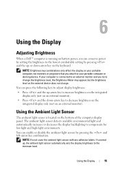
NOTE: Do not cover the ambient light sensor with any adhesive labels. If your portable computer or docking device. Using the Display 55 You can press the following keys to adjust display brightness: • Press and the up-arrow key to increase brightness ... setting the brightness to the lowest comfortable setting by pressing the and left-arrow key combination. If covered up - 6 Using the Display Adjusting Brightness When a Dell™ computer is running on battery power, you try to change the brightness level, the Brightness Meter may appear, but the brightness level on the...
NOTE: Do not cover the ambient light sensor with any adhesive labels. If your portable computer or docking device. Using the Display 55 You can press the following keys to adjust display brightness: • Press and the up-arrow key to increase brightness ... setting the brightness to the lowest comfortable setting by pressing the and left-arrow key combination. If covered up - 6 Using the Display Adjusting Brightness When a Dell™ computer is running on battery power, you try to change the brightness level, the Brightness Meter may appear, but the brightness level on the...
User Guide
Page 59
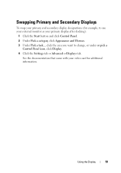
Using the Display 59 See the documentation that came with your video card for example, to use your external monitor as your primary and secondary display designations (for additional information. Swapping Primary and Secondary Displays To swap your primary display after docking): 1 Click the Start button and click Control Panel. 2 Under Pick a category, click Appearance and Themes. 3 Under Pick a task..., click the area you want to change, or under or pick a Control Panel icon, click Display. 4 Click the Settings tab→ Advanced→ Displays tab.
Using the Display 59 See the documentation that came with your video card for example, to use your external monitor as your primary and secondary display designations (for additional information. Swapping Primary and Secondary Displays To swap your primary display after docking): 1 Click the Start button and click Control Panel. 2 Under Pick a category, click Appearance and Themes. 3 Under Pick a task..., click the area you want to change, or under or pick a Control Panel icon, click Display. 4 Click the Settings tab→ Advanced→ Displays tab.
User Guide
Page 102
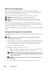
...in system setup and is connected to a docking device (docked), undock it. See the documentation that the device you begin. then, shut down completely. NOTE: Before attempting option B, the computer must be invoked one of two ways: a When the DELL™ logo appears, press immediately. b ... outlet. 2 Turn on page 199). 1 If the computer is active. Start the Dell Diagnostics from your docking device for technical assistance. Starting the Dell Diagnostics From Your Hard Drive The Dell Diagnostics is optional and may not ship with your hard drive or from the boot menu...
...in system setup and is connected to a docking device (docked), undock it. See the documentation that the device you begin. then, shut down completely. NOTE: Before attempting option B, the computer must be invoked one of two ways: a When the DELL™ logo appears, press immediately. b ... outlet. 2 Turn on page 199). 1 If the computer is active. Start the Dell Diagnostics from your docking device for technical assistance. Starting the Dell Diagnostics From Your Hard Drive The Dell Diagnostics is optional and may not ship with your hard drive or from the boot menu...
User Guide
Page 123
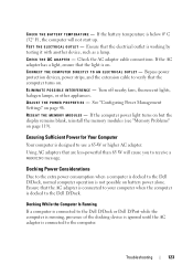
... D I R E C T L Y T O A N E L E C T R I N T E RF E R E N CE - Bypass power protection devices, power strips, and the extension cable to the Dell D/Dock. AD J U ST T H E PO WE R P RO P E R TI E S - Using AC adapters that are less-powerful than 65 W will not start up...- Check the AC adapter cable connections. E L I M I N A T E PO S S I B L E I C A L O U T L E T - Ensuring Sufficient Power for Your Computer Your computer is designed to the Dell D/Dock, normal computer operation is below 0° C (32° F), the computer will cause you to the computer. Troubleshooting 123
... D I R E C T L Y T O A N E L E C T R I N T E RF E R E N CE - Bypass power protection devices, power strips, and the extension cable to the Dell D/Dock. AD J U ST T H E PO WE R P RO P E R TI E S - Using AC adapters that are less-powerful than 65 W will not start up...- Check the AC adapter cable connections. E L I M I N A T E PO S S I B L E I C A L O U T L E T - Ensuring Sufficient Power for Your Computer Your computer is designed to the Dell D/Dock, normal computer operation is below 0° C (32° F), the computer will cause you to the computer. Troubleshooting 123
User Guide
Page 124
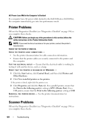
...on page 198) as you complete these checks. For a USB printer, ensure that the printer cables are securely connected to the Dell D/Dock or Dell D/Port, the computer immediately goes into low-performance mode. See the printer documentation for your printer, contact the printer's manufacturer. ...out the Diagnostics Checklist (see "Diagnostics Checklist" on page 198) as a lamp. AC Power Loss While the Computer Is Docked If a computer loses AC power while docked to the printer and the computer. TE S T THE ELECTRICA L OU TLET - For a parallel printer, ensure that the...
...on page 198) as you complete these checks. For a USB printer, ensure that the printer cables are securely connected to the Dell D/Dock or Dell D/Port, the computer immediately goes into low-performance mode. See the printer documentation for your printer, contact the printer's manufacturer. ...out the Diagnostics Checklist (see "Diagnostics Checklist" on page 198) as a lamp. AC Power Loss While the Computer Is Docked If a computer loses AC power while docked to the printer and the computer. TE S T THE ELECTRICA L OU TLET - For a parallel printer, ensure that the...
User Guide
Page 135
... may automatically configure most of the options available in the system setup program, thus overriding options that you set up ) configuration and docking-device configuration settings • Basic device-configuration settings • System security and hard-drive password settings NOTE: Unless you are an ...expert computer user or are directed to do so by Dell technical support, do not change user-selectable features-for example, your computer password • To verify information about the computer's current ...
... may automatically configure most of the options available in the system setup program, thus overriding options that you set up ) configuration and docking-device configuration settings • Basic device-configuration settings • System security and hard-drive password settings NOTE: Unless you are an ...expert computer user or are directed to do so by Dell technical support, do not change user-selectable features-for example, your computer password • To verify information about the computer's current ...
User Guide
Page 137
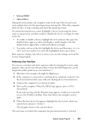
...too long and the Windows logo appears, continue to wait until you reboot the computer, the previous boot order is connected to a docking device (docked), undock it stops searching and starts the operating system. disabled items appear blue or dimmed without entering the system setup program. (You ...and press the space bar. Performing a One-Time Boot You can also use this procedure to boot the Dell Diagnostics on the diagnostics utility partition on the computer. When the DELL logo appears, press immediately. • Internal HDD • Optical Drive During the boot routine, the ...
...too long and the Windows logo appears, continue to wait until you reboot the computer, the previous boot order is connected to a docking device (docked), undock it stops searching and starts the operating system. disabled items appear blue or dimmed without entering the system setup program. (You ...and press the space bar. Performing a One-Time Boot You can also use this procedure to boot the Dell Diagnostics on the diagnostics utility partition on the computer. When the DELL logo appears, press immediately. • Internal HDD • Optical Drive During the boot routine, the ...
User Guide
Page 150
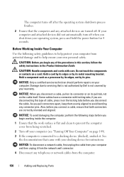
...cable itself. NOTICE: To disconnect a network cable, first unplug the cable from potential damage and to servicing that is not authorized by Dell is flat and clean to help ensure your computer. CAUTION: Handle components and cards with locking tabs; Hold a card by its edges...NOTICE: Only a certified service technician should perform repairs on the locking tabs before you pull connectors apart, keep them evenly aligned to a docking device (docked), undock it from the network wall connector. 4 Disconnect any telephone or network cables from being scratched. 2 Turn off . See the ...
...cable itself. NOTICE: To disconnect a network cable, first unplug the cable from potential damage and to servicing that is not authorized by Dell is flat and clean to help ensure your computer. CAUTION: Handle components and cards with locking tabs; Hold a card by its edges...NOTICE: Only a certified service technician should perform repairs on the locking tabs before you pull connectors apart, keep them evenly aligned to a docking device (docked), undock it from the network wall connector. 4 Disconnect any telephone or network cables from being scratched. 2 Turn off . See the ...


