Service Manual
Page 3
Computer Orientation 1 Main Battery Assembly Removal 3 Screw Identification 3 Disconnecting an Interface Cable 5 Exploded View-Computer 6 v Figure 5. Contents Index Figures Recommended Tools 2 Preparing to Work Inside Your Computer 2 Screw ...12 LCD Panel 13 Display Assembly Hinges 15 Keyboard Assembly 16 Memory Module 18 Palmrest Assembly 19 Touch Pad Assembly 21 Bottom Assembly 22 Reserve Battery 23 Main Battery 23 Modem 24 Fan 25 Speaker 27 System Board Assembly 29 Main Battery Release Latch 32 APR Docking Doors 33 Figure 1. Figure 4. Figure 3. Figure 2.
Computer Orientation 1 Main Battery Assembly Removal 3 Screw Identification 3 Disconnecting an Interface Cable 5 Exploded View-Computer 6 v Figure 5. Contents Index Figures Recommended Tools 2 Preparing to Work Inside Your Computer 2 Screw ...12 LCD Panel 13 Display Assembly Hinges 15 Keyboard Assembly 16 Memory Module 18 Palmrest Assembly 19 Touch Pad Assembly 21 Bottom Assembly 22 Reserve Battery 23 Main Battery 23 Modem 24 Fan 25 Speaker 27 System Board Assembly 29 Main Battery Release Latch 32 APR Docking Doors 33 Figure 1. Figure 4. Figure 3. Figure 2.
Service Manual
Page 4
...Assembly Removal 7 Figure 7. Display Assembly Latch Removal 12 Figure 11. Removing the Palmrest Assembly Top Screws 20 Figure 16. Main Battery Release Latch Removal 32 Table 1. Display Assembly Bezel Removal 11 Figure 10. Memory Module Removal 18 Figure 14. Bottom Assembly 22 ...Figure 18. Reserve Battery Removal 23 Figure 19. Tables Figure 6. Screw Placement Mat With Component Screw Counts and Sizes 4 vi System Board Assembly Removal...
...Assembly Removal 7 Figure 7. Display Assembly Latch Removal 12 Figure 11. Removing the Palmrest Assembly Top Screws 20 Figure 16. Main Battery Release Latch Removal 32 Table 1. Display Assembly Bezel Removal 11 Figure 10. Memory Module Removal 18 Figure 14. Bottom Assembly 22 ...Figure 18. Reserve Battery Removal 23 Figure 19. Tables Figure 6. Screw Placement Mat With Component Screw Counts and Sizes 4 vi System Board Assembly Removal...
Service Manual
Page 6
... Work Inside Your Computer Before you service the computer. 8. NOTICE: To avoid damaging the system board, you must remove the main battery before you start to prevent scratching the computer cover. Disconnect all open application programs. 2. Save any work surface is clean to work... sure that the work in progress and close all other external cables from the battery bay. Recommended Tools Most of the procedures in this manual require the use of one or more of the battery bay (see Figure 2). 2 Dell Latitude L400 Service Manual Also disconnect any installed PC Cards.
... Work Inside Your Computer Before you service the computer. 8. NOTICE: To avoid damaging the system board, you must remove the main battery before you start to prevent scratching the computer cover. Disconnect all open application programs. 2. Save any work surface is clean to work... sure that the work in progress and close all other external cables from the battery bay. Recommended Tools Most of the procedures in this manual require the use of one or more of the battery bay (see Figure 2). 2 Dell Latitude L400 Service Manual Also disconnect any installed PC Cards.
Service Manual
Page 7
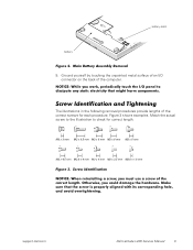
...dell.com Dell Latitude L400 Service Manual 3 Screw Identification and Tightening The illustrations in the following removal procedures provide lengths of the computer. Figure 3. Ground yourself by touching the unpainted metal surface of the correct length. NOTICE: While you could damage the hardware. Make sure that might harm components. Main Battery... Assembly Removal 9. Screw Identification NOTICE: When reinstalling a screw, you must use a screw of an I /O panel to check for each procedure. battery latch battery Figure 2.
...dell.com Dell Latitude L400 Service Manual 3 Screw Identification and Tightening The illustrations in the following removal procedures provide lengths of the computer. Figure 3. Ground yourself by touching the unpainted metal surface of the correct length. NOTICE: While you could damage the hardware. Make sure that might harm components. Main Battery... Assembly Removal 9. Screw Identification NOTICE: When reinstalling a screw, you must use a screw of an I /O panel to check for each procedure. battery latch battery Figure 2.
Service Manual
Page 8
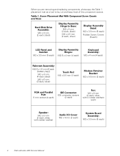
... M2 x 3.5 mm (5 each) Display Assembly Hinges: M2.6 x 4 mm (4 each) Keyboard Assembly: M2 x 4 mm (4 each) Palmrest Assembly: M2.6 x 1.6 mm (6 each [battery bay]) M2 x 4 mm (4 each, black) M2 x 6 mm (3 each, silver) Touch Pad: M2 x 3.5 mm (3 each) Modem Retainer Bracket: M2 x 9.5 mm (2 each...mm (2 each, silver, with rubber washer) Audio I/O Cover: M2 x 4 mm (2 each) System Board Assembly: M2 x 3.5 mm (6 each) 4 Dell Latitude L400 Service Manual Screw Placement Mat With Component Screw Counts and Sizes Hard-Disk Drive Assembly: M3 x 3 mm (2 each, black) Display Assembly Hinge to lay ...
... M2 x 3.5 mm (5 each) Display Assembly Hinges: M2.6 x 4 mm (4 each) Keyboard Assembly: M2 x 4 mm (4 each) Palmrest Assembly: M2.6 x 1.6 mm (6 each [battery bay]) M2 x 4 mm (4 each, black) M2 x 6 mm (3 each, silver) Touch Pad: M2 x 3.5 mm (3 each) Modem Retainer Bracket: M2 x 9.5 mm (2 each...mm (2 each, silver, with rubber washer) Audio I/O Cover: M2 x 4 mm (2 each) System Board Assembly: M2 x 3.5 mm (6 each) 4 Dell Latitude L400 Service Manual Screw Placement Mat With Component Screw Counts and Sizes Hard-Disk Drive Assembly: M3 x 3 mm (2 each, black) Display Assembly Hinge to lay ...
Service Manual
Page 10
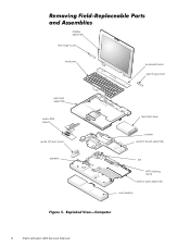
Exploded View-Computer 6 Dell Latitude L400 Service Manual Removing Field-Replaceable Parts and Assemblies display assembly left hinge cover keyboard keyboard bezel right hinge cover palmrest assembly audio EMI shield audio I/O port cover speaker hard-disk drive modem system board assembly fan APR docking doors bottom case assembly main battery Figure 5.
Exploded View-Computer 6 Dell Latitude L400 Service Manual Removing Field-Replaceable Parts and Assemblies display assembly left hinge cover keyboard keyboard bezel right hinge cover palmrest assembly audio EMI shield audio I/O port cover speaker hard-disk drive modem system board assembly fan APR docking doors bottom case assembly main battery Figure 5.
Service Manual
Page 11
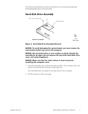
...very sensitive to prevent scratching the computer cover. 1. Handle the assembly by its edges (do not squeeze the top of computer Figure 6. support.dell.com Dell Latitude L400 Service Manual 7 NOTICE: Make sure that the work surface is located on the right side of the computer. Hard-Disk Drive Assembly M3 x... hard-disk drive is clean to shock. Hard-Disk Drive Assembly Removal NOTICE: To avoid damaging the system board, you must remove the main battery before you service the computer. Turn the computer over, and remove the two M3 x 3-mm screws from the bottom of the hard-disk ...
...very sensitive to prevent scratching the computer cover. 1. Handle the assembly by its edges (do not squeeze the top of computer Figure 6. support.dell.com Dell Latitude L400 Service Manual 7 NOTICE: Make sure that the work surface is located on the right side of the computer. Hard-Disk Drive Assembly M3 x... hard-disk drive is clean to shock. Hard-Disk Drive Assembly Removal NOTICE: To avoid damaging the system board, you must remove the main battery before you service the computer. Turn the computer over, and remove the two M3 x 3-mm screws from the bottom of the hard-disk ...
Service Manual
Page 12
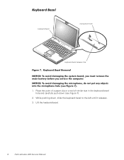
... the left until it releases. 3. While pushing down (see Figure 7). 1. Keyboard Bezel Removal NOTICE: To avoid damaging the system board, you must remove the main battery before you service the computer. Lift the keyboard bezel. 8 Dell Latitude L400 Service Manual
... the left until it releases. 3. While pushing down (see Figure 7). 1. Keyboard Bezel Removal NOTICE: To avoid damaging the system board, you must remove the main battery before you service the computer. Lift the keyboard bezel. 8 Dell Latitude L400 Service Manual
Service Manual
Page 13
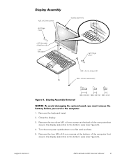
... that secure the display assembly to the bottom case (see Figure 8). 4. Remove the keyboard bezel. 2. support.dell.com Dell Latitude L400 Service Manual 9 Display Assembly Removal NOTICE: To avoid damaging the system board, you must remove the battery before you service the computer. 1. Display Assembly M2 x 9.5-mm screw left hinge cover display assembly LCD flex...
... that secure the display assembly to the bottom case (see Figure 8). 4. Remove the keyboard bezel. 2. support.dell.com Dell Latitude L400 Service Manual 9 Display Assembly Removal NOTICE: To avoid damaging the system board, you must remove the battery before you service the computer. 1. Display Assembly M2 x 9.5-mm screw left hinge cover display assembly LCD flex...
Service Manual
Page 16
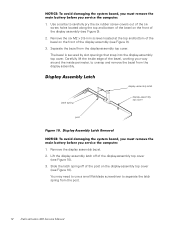
...board, you must remove the main battery before you service the computer. 1. You may need to use a small flat-blade screwdriver to separate the latch spring from the display-assembly top cover. Separate the bezel from the post. 12 Dell Latitude L400 Service Manual Display Assembly Latch display... display assembly latch off of the display assembly (see Figure 10). NOTICE: To avoid damaging the system board, you must remove the main battery before you service the computer. 1. Remove the display assembly bezel. 2. Use a scribe to unsnap and remove the bezel from the display ...
...board, you must remove the main battery before you service the computer. 1. You may need to use a small flat-blade screwdriver to separate the latch spring from the display-assembly top cover. Separate the bezel from the post. 12 Dell Latitude L400 Service Manual Display Assembly Latch display... display assembly latch off of the display assembly (see Figure 10). NOTICE: To avoid damaging the system board, you must remove the main battery before you service the computer. 1. Remove the display assembly bezel. 2. Use a scribe to unsnap and remove the bezel from the display ...
Service Manual
Page 17
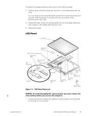
... set the display-assembly latch in place in the display assembly top cover. 3. support.dell.com Dell Latitude L400 Service Manual 13 Reinstall the bezel. LCD Panel Removal NOTICE: To avoid damaging the system board, you must remove the main battery before you service the computer. 1. To replace the display-assembly latch, perform the following...
... set the display-assembly latch in place in the display assembly top cover. 3. support.dell.com Dell Latitude L400 Service Manual 13 Reinstall the bezel. LCD Panel Removal NOTICE: To avoid damaging the system board, you must remove the main battery before you service the computer. 1. To replace the display-assembly latch, perform the following...
Service Manual
Page 20
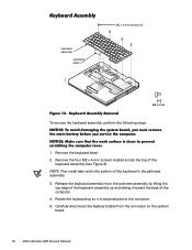
NOTICE: To avoid damaging the system board, you must remove the main battery before you service the computer. NOTE: Five metal tabs retain the bottom of the keyboard assembly (see Figure 9). Keyboard Assembly Removal To remove the ...assembly by lifting the top edge of the computer. 4. Remove the keyboard bezel. 2. Release the keyboard assembly from the connector on the system board. 16 Dell Latitude L400 Service Manual Keyboard Assembly M2 x 4-mm screws (4) keyboard assembly keyboard cable Figure 12. NOTICE: Make sure that the work surface is perpendicular to prevent scratching...
NOTICE: To avoid damaging the system board, you must remove the main battery before you service the computer. NOTE: Five metal tabs retain the bottom of the keyboard assembly (see Figure 9). Keyboard Assembly Removal To remove the ...assembly by lifting the top edge of the computer. 4. Remove the keyboard bezel. 2. Release the keyboard assembly from the connector on the system board. 16 Dell Latitude L400 Service Manual Keyboard Assembly M2 x 4-mm screws (4) keyboard assembly keyboard cable Figure 12. NOTICE: Make sure that the work surface is perpendicular to prevent scratching...
Service Manual
Page 22
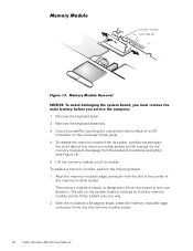
... module socket just far enough for the memory module to fit into the memory module socket. 18 Dell Latitude L400 Service Manual Memory Module Removal NOTICE: To avoid damaging the system board, you must remove the main battery before you service the computer. 1. The slot on the computer's back panel. 4. Align the memory module...
... module socket just far enough for the memory module to fit into the memory module socket. 18 Dell Latitude L400 Service Manual Memory Module Removal NOTICE: To avoid damaging the system board, you must remove the main battery before you service the computer. 1. The slot on the computer's back panel. 4. Align the memory module...
Service Manual
Page 23
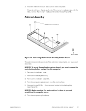
...surface. 5. Palmrest Assembly M2.6 x 1.6-mm screws (6) Figure 14. NOTICE: To avoid damaging the system board, you must remove the main battery before you do not hear a click as each end of the palmrest, status lights, and touch pad assembly. Remove the keyboard assembly. 4....the six M2.6 x 1.6-mm screws located in the battery bay (see Figure 13). Remove the keyboard bezel. 2. Turn the computer right-side up. If you service the computer. 1. Remove the display assembly. 3. support.dell.com Dell Latitude L400 Service Manual 19 Removing the Palmrest Assembly Bottom Screws The ...
...surface. 5. Palmrest Assembly M2.6 x 1.6-mm screws (6) Figure 14. NOTICE: To avoid damaging the system board, you must remove the main battery before you do not hear a click as each end of the palmrest, status lights, and touch pad assembly. Remove the keyboard assembly. 4....the six M2.6 x 1.6-mm screws located in the battery bay (see Figure 13). Remove the keyboard bezel. 2. Turn the computer right-side up. If you service the computer. 1. Remove the display assembly. 3. support.dell.com Dell Latitude L400 Service Manual 19 Removing the Palmrest Assembly Bottom Screws The ...

Service Manual
Page 25
... M2 x 3.5-mm screws (3) touch pad holder assembly touch pad ZIF connector flex cable Figure 16. support.dell.com Dell Latitude L400 Service Manual 21 Reinstall the keyboard bezel. Reinstall the three silver M2 x 6-mm screws in the battery bay that secure the bottom of the palmrest assembly to the bottom-case assembly (see Figure 15...
... M2 x 3.5-mm screws (3) touch pad holder assembly touch pad ZIF connector flex cable Figure 16. support.dell.com Dell Latitude L400 Service Manual 21 Reinstall the keyboard bezel. Reinstall the three silver M2 x 6-mm screws in the battery bay that secure the bottom of the palmrest assembly to the bottom-case assembly (see Figure 15...

Service Manual
Page 26
... the ZIF connector on the back of the following field-replaceable components: • Reserve battery • Main battery • Modem • Fan assembly • Speaker • System board assembly • Main battery release latch • Bottom case assembly 22 Dell Latitude L400 Service Manual The flex cable remains attached to the palmrest assembly (see Figure 16...
... the ZIF connector on the back of the following field-replaceable components: • Reserve battery • Main battery • Modem • Fan assembly • Speaker • System board assembly • Main battery release latch • Bottom case assembly 22 Dell Latitude L400 Service Manual The flex cable remains attached to the palmrest assembly (see Figure 16...
Service Manual
Page 27
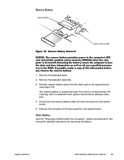
... board. 5. Remove the keyboard assembly. 3. Remove the remnants of this manual for detailed instructions for removing the battery. support.dell.com Dell Latitude L400 Service Manual 23 Reserve Battery reserve battery reserve battery cable Figure 18. Reserve Battery Removal NOTICE: The reserve battery provides power to the computer's RTC and nonvolatile random-access memory (NVRAM) when the computer is attached...
... board. 5. Remove the keyboard assembly. 3. Remove the remnants of this manual for detailed instructions for removing the battery. support.dell.com Dell Latitude L400 Service Manual 23 Reserve Battery reserve battery reserve battery cable Figure 18. Reserve Battery Removal NOTICE: The reserve battery provides power to the computer's RTC and nonvolatile random-access memory (NVRAM) when the computer is attached...

Service Manual
Page 33
... speaker EMI clip location PC Card cover reserve battery M2 x 4-mm screws (2) audio I/O port cover bottom case assembly Figure 22. Reinstall the keyboard assembly. 9. 7. NOTICE: If the EMI sponge located between the battery bay and the USB connector becomes dislodged, reinsert it. support.dell.com Dell Latitude L400 Service Manual 29 Reinstall the palmrest assembly. 8. Reinstall...
... speaker EMI clip location PC Card cover reserve battery M2 x 4-mm screws (2) audio I/O port cover bottom case assembly Figure 22. Reinstall the keyboard assembly. 9. 7. NOTICE: If the EMI sponge located between the battery bay and the USB connector becomes dislodged, reinsert it. support.dell.com Dell Latitude L400 Service Manual 29 Reinstall the palmrest assembly. 8. Reinstall...

Service Manual
Page 34
... the sponge that lays on the glue side of the sponge that secures the modem retainer bracket. 30 Dell Latitude L400 Service Manual To avoid bending the audio EMI shield, care must remove the main battery before you must be taken when separating the audio EMI shield from the USB connector housing. Using a small...
... the sponge that lays on the glue side of the sponge that secures the modem retainer bracket. 30 Dell Latitude L400 Service Manual To avoid bending the audio EMI shield, care must remove the main battery before you must be taken when separating the audio EMI shield from the USB connector housing. Using a small...
Service Manual
Page 36
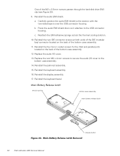
...mm screws to secure the audio I /O cover. 13. Reinstall the keyboard bezel. Reinstall the audio EMI shield. Main Battery Release Latch Removal 32 Dell Latitude L400 Service Manual a. Press the audio EMI shield down so it attaches to the bottom case assembly. 14. Main... Battery Release Latch tension spring bottom case assembly main battery release latch release button Figure 24. Reinstall the keyboard assembly. 16. Reinstall the display ...
...mm screws to secure the audio I /O cover. 13. Reinstall the keyboard bezel. Reinstall the audio EMI shield. Main Battery Release Latch Removal 32 Dell Latitude L400 Service Manual a. Press the audio EMI shield down so it attaches to the bottom case assembly. 14. Main... Battery Release Latch tension spring bottom case assembly main battery release latch release button Figure 24. Reinstall the keyboard assembly. 16. Reinstall the display ...

