
Owner's Manual
Page 3
... Battery...11 Installing the Battery...12 Removing the Base Cover...12 Installing the Base Cover...14 Removing the mSATA SSD Card...14 Installing the mSATA SSD Card...14 Removing the Keyboard Trim...14 Installing the Keyboard Trim...15 Removing the Keyboard...15 Installing the Keyboard...16 Removing the Palmrest...16 Installing the Palmrest...17 Removing the Wi‐Fi Switch Board...17 Installing the Wi‐Fi Switch Board...18 Removing the Memory Module...18 Installing the Memory Module...19 Removing the WLAN Card...19 Installing...
... Battery...11 Installing the Battery...12 Removing the Base Cover...12 Installing the Base Cover...14 Removing the mSATA SSD Card...14 Installing the mSATA SSD Card...14 Removing the Keyboard Trim...14 Installing the Keyboard Trim...15 Removing the Keyboard...15 Installing the Keyboard...16 Removing the Palmrest...16 Installing the Palmrest...17 Removing the Wi‐Fi Switch Board...17 Installing the Wi‐Fi Switch Board...18 Removing the Memory Module...18 Installing the Memory Module...19 Removing the WLAN Card...19 Installing...
Owner's Manual
Page 4
... Board...28 Removing the Power Connector ...29 Installing the Power Connector...29 3 Docking Port Information...31 4 System Setup...33 Boot Sequence...33 Navigation Keys...33 System Setup Options...34 Updating the BIOS ...43 System and Setup Password...44 Assigning a System Password and Setup Password 44 Deleting or Changing an Existing System and/or Setup Password 45 5 Diagnostics...47 Enhanced Pre-Boot System Assessment (ePSA) Diagnostics 47 Device Status Lights...47 Battery Status Lights...48 6 Specifications...49 7 Contacting Dell...
... Board...28 Removing the Power Connector ...29 Installing the Power Connector...29 3 Docking Port Information...31 4 System Setup...33 Boot Sequence...33 Navigation Keys...33 System Setup Options...34 Updating the BIOS ...43 System and Setup Password...44 Assigning a System Password and Setup Password 44 Deleting or Changing an Existing System and/or Setup Password 45 5 Diagnostics...47 Enhanced Pre-Boot System Assessment (ePSA) Diagnostics 47 Device Status Lights...47 Battery Status Lights...48 6 Specifications...49 7 Contacting Dell...

Owner's Manual
Page 5
... order. 1 Working on a card. For additional safety best practices information, see Turning Off Your Computer). 3. Read and follow the safety instructions that shipped with your computer (see the Regulatory Compliance Homepage at www.dell.com/ regulatory_compliance CAUTION: Many repairs may appear differently than shown in on the cable itself. NOTE: The color of the computer. Disconnect all attached devices...
... order. 1 Working on a card. For additional safety best practices information, see Turning Off Your Computer). 3. Read and follow the safety instructions that shipped with your computer (see the Regulatory Compliance Homepage at www.dell.com/ regulatory_compliance CAUTION: Many repairs may appear differently than shown in on the cable itself. NOTE: The color of the computer. Disconnect all attached devices...
Owner's Manual
Page 6
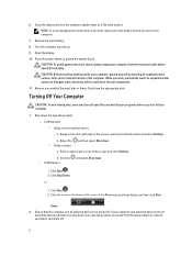
... computer. 1. In Windows 8: * Using a touch-enabled device: a. Click the - If your computer and attached devices did not automatically turn off your computer from the appropriate slots. CAUTION: Before touching anything inside your operating system, press and hold the power button for about 4 seconds to upper-right corner of the Start menu as the metal at the back of the screen, opening the display. Select the * Using a mouse: and then...
... computer. 1. In Windows 8: * Using a touch-enabled device: a. Click the - If your computer and attached devices did not automatically turn off your computer from the appropriate slots. CAUTION: Before touching anything inside your operating system, press and hold the power button for about 4 seconds to upper-right corner of the Start menu as the metal at the back of the screen, opening the display. Select the * Using a mouse: and then...

Owner's Manual
Page 7
... computer, use batteries designed for this particular Dell computer. Do not use only the battery designed for other Dell computers. 1. CAUTION: To avoid damage to their electrical outlets. 5. CAUTION: To connect a network cable, first plug the cable into the network device and then plug it into the computer. 3. Turn on your computer. Replace the battery. 4. Connect any external devices, such as a port replicator, battery slice, or media base, and replace any cards, such...
... computer, use batteries designed for this particular Dell computer. Do not use only the battery designed for other Dell computers. 1. CAUTION: To avoid damage to their electrical outlets. 5. CAUTION: To connect a network cable, first plug the cable into the network device and then plug it into the computer. 3. Turn on your computer. Replace the battery. 4. Connect any external devices, such as a port replicator, battery slice, or media base, and replace any cards, such...

Owner's Manual
Page 18
... its slot. 2. Connect the wi-fi switch board to the system board. 4. Follow the procedures in Before Working Inside Your Computer. 2. Remove: a) battery b) base cover 3. Pry the securing clips away from the system board and remove the screw that secures the wi-fi switch board to the system board. 3. Installing the Wi‐Fi Switch Board 1. Disconnect the wi-fi switch board cable from the memory module until it pops up. Install: a) palmrest b) keyboard c) keyboard...
... its slot. 2. Connect the wi-fi switch board to the system board. 4. Follow the procedures in Before Working Inside Your Computer. 2. Remove: a) battery b) base cover 3. Pry the securing clips away from the system board and remove the screw that secures the wi-fi switch board to the system board. 3. Installing the Wi‐Fi Switch Board 1. Disconnect the wi-fi switch board cable from the memory module until it pops up. Install: a) palmrest b) keyboard c) keyboard...
Owner's Manual
Page 34
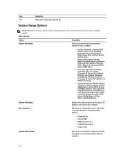
...; Diskette Drive • Internal HDD • USB Storage Device • CD/DVD/CD-RW Drive • Onboard NIC Advance Boot Option This option is enabled. 34 This option is not allowed if Secure Boot is required for Legacy boot mode. Keys Navigation Displays the System Setup help file. Table 2. General Option System Information Description This section lists the primary hardware features of AC adapter connected to the computer Allows you to change the order in...
...; Diskette Drive • Internal HDD • USB Storage Device • CD/DVD/CD-RW Drive • Onboard NIC Advance Boot Option This option is enabled. 34 This option is not allowed if Secure Boot is required for Legacy boot mode. Keys Navigation Displays the System Setup help file. Table 2. General Option System Information Description This section lists the primary hardware features of AC adapter connected to the computer Allows you to change the order in...
Owner's Manual
Page 36
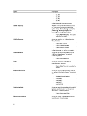
.... Allows you to define the USB configuration. The options are reported during system startup. This technology is disabled by default. This option is part of the USB PowerShare feature. Option SMART Reporting USB Configuration USB PowerShare Audio Keyboard Illumination Unobtrusive Mode Miscellaneous Devices 36 Description • SATA-0 • SATA-1 • SATA-2 • SATA-3 Default Setting: All drives are : • Enable Boot Support • Enable External USB Port • Enable USB3.0 Controller Default Setting: all light and sound emissions from the system. The...
.... Allows you to define the USB configuration. The options are reported during system startup. This technology is disabled by default. This option is part of the USB PowerShare feature. Option SMART Reporting USB Configuration USB PowerShare Audio Keyboard Illumination Unobtrusive Mode Miscellaneous Devices 36 Description • SATA-0 • SATA-1 • SATA-2 • SATA-3 Default Setting: All drives are : • Enable Boot Support • Enable External USB Port • Enable USB3.0 Controller Default Setting: all light and sound emissions from the system. The...
Owner's Manual
Page 37
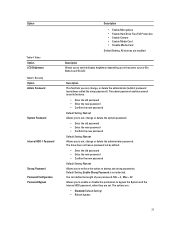
... Option Admin Password System Password Internal HDD-1 Password Strong Password Password Configuration Password Bypass Description • Enable Microphone • Enable Hard Drive Free Fall Protection • Enable Camera • Enable Media Card • Disable Media Card Default Setting: All devices are enabled Description Allows you set the display brightness depending up on the power source (On Battery and On AC). The drive does not have a password set by default. • Enter the old password • Enter the new password • Confirm the new password Default Setting: Not set...
... Option Admin Password System Password Internal HDD-1 Password Strong Password Password Configuration Password Bypass Description • Enable Microphone • Enable Hard Drive Free Fall Protection • Enable Camera • Enable Media Card • Disable Media Card Default Setting: All devices are enabled Description Allows you set the display brightness depending up on the power source (On Battery and On AC). The drive does not have a password set by default. • Enter the old password • Enter the new password • Confirm the new password Default Setting: Not set...
Owner's Manual
Page 38
... whether changes to enter the Option ROM Configuration screens using hotkeys during POST. The options are : • Deactivate (Default Setting) • Disable • Activate NOTE: The Activate and Disable options will permanently activate or disable the feature and no further changes will be turned off. Default Setting: Disabled Allows you to set . Default Setting: Enable CPU XD Support Allows you to enable or disable Secure Boot feature • Disabled • Enabled(Default Setting) NOTE: For enable system needs to be UEFI boot mode and enable legacy option ROMs to...
... whether changes to enter the Option ROM Configuration screens using hotkeys during POST. The options are : • Deactivate (Default Setting) • Disable • Activate NOTE: The Activate and Disable options will permanently activate or disable the feature and no further changes will be turned off. Default Setting: Disabled Allows you to set . Default Setting: Enable CPU XD Support Allows you to enable or disable Secure Boot feature • Disabled • Enabled(Default Setting) NOTE: For enable system needs to be UEFI boot mode and enable legacy option ROMs to...
Owner's Manual
Page 41
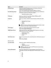
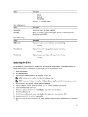
... battery must be disabled in order to define how the computer handles the mouse and touchpad input. Battery Slice Configuration (Latitude 7240) Allows you to enable this option has no effect, Setup works in the "Fn Key Only" mode. The options are : • Standard Charge • Express Charge (Default Setting) Intel Smart Connect Technology The option is plugged in. The options are: • Adaptive(Enabled) • Standard Charge • Express Charge • Primary AC Use • Custom Charge...
... battery must be disabled in order to define how the computer handles the mouse and touchpad input. Battery Slice Configuration (Latitude 7240) Allows you to enable this option has no effect, Setup works in the "Fn Key Only" mode. The options are : • Standard Charge • Express Charge (Default Setting) Intel Smart Connect Technology The option is plugged in. The options are: • Adaptive(Enabled) • Standard Charge • Express Charge • Primary AC Use • Custom Charge...

Owner's Manual
Page 42
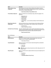
... match the key feature of PS-2 keyboard with the key feature in an internal keyboard. Allows you to enable or disable the wireless devices. The option is enabled by default. • Enable Fn Key Emulation Allows you to speed up the boot process by default. Option Numlock Enable Fn Key Emulation Fastboot Extended BIOS POST Time Table 10. Wireless Option Wireless Switch Wireless Device Enable Description Specifies if the NumLock function can utilize the additional hardware capabilities provided by the wireless switch.
... match the key feature of PS-2 keyboard with the key feature in an internal keyboard. Allows you to enable or disable the wireless devices. The option is enabled by default. • Enable Fn Key Emulation Allows you to speed up the boot process by default. Option Numlock Enable Fn Key Emulation Fastboot Extended BIOS POST Time Table 10. Wireless Option Wireless Switch Wireless Device Enable Description Specifies if the NumLock function can utilize the additional hardware capabilities provided by the wireless switch.
Owner's Manual
Page 43
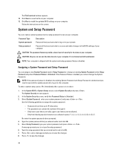
...; Clear Log Updating the BIOS It is not set . Proceed with the instructions on replacing the system board or if an update is not already set by default. If you are enabled by default. Select your computer model and the Product Support page of your Service Tag, click Detect Service Tag. Click Drivers & Downloads. 9. click Download File. 43 Allows you to locate or find your computer. 6. This option is recommended to create...
...; Clear Log Updating the BIOS It is not set . Proceed with the instructions on replacing the system board or if an update is not already set by default. If you are enabled by default. Select your computer model and the Product Support page of your Service Tag, click Detect Service Tag. Click Drivers & Downloads. 9. click Download File. 43 Allows you to locate or find your computer. 6. This option is recommended to create...
Owner's Manual
Page 44
... deleted and you cannot change an existing System Password and/or Setup Password only when Password Status is Unlocked. 3. The File Download window appears. 12. The password can access the data stored on to the BIOS settings of security for the data on your computer. To enter a system setup, press immediately after a power-on the screen. Password Type System password Setup password Description Password that you must enter to access and make changes to your computer.
... deleted and you cannot change an existing System Password and/or Setup Password only when Password Status is Unlocked. 3. The File Download window appears. 12. The password can access the data stored on to the BIOS settings of security for the data on your computer. To enter a system setup, press immediately after a power-on the screen. Password Type System password Setup password Description Password that you must enter to access and make changes to your computer.

Owner's Manual
Page 47
... BIOS internally. NOTE: Some tests for particular devices or device groups allowing you to stop the diagnostic test. 5. If you are displayed. Using this program with the BIOS and is embedded with other computers may cause invalid results or error messages. As the computer boots, press the key as system diagnostics) performs a complete check of options for specific devices require user interaction. On the boot menu screen...
... BIOS internally. NOTE: Some tests for particular devices or device groups allowing you to stop the diagnostic test. 5. If you are displayed. Using this program with the BIOS and is embedded with other computers may cause invalid results or error messages. As the computer boots, press the key as system diagnostics) performs a complete check of options for specific devices require user interaction. On the boot menu screen...
Owner's Manual
Page 48
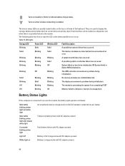
... card/video failure has occurred. Solid Blinking Blinking No memory modules are detected but has encountered an error. The following table lists how to the system. Blinking Solid Blinking The display encountered a problem during initialization. Battery Status Lights If the computer is connected to display the storage, battery and wireless devices connectivity and activity. Apart from completing POST Off Blinking Off Memory failed to initialize or memory is attached to indicate battery charge status. Table 15. Blinking Blinking Blinking A system board...
... card/video failure has occurred. Solid Blinking Blinking No memory modules are detected but has encountered an error. The following table lists how to the system. Blinking Solid Blinking The display encountered a problem during initialization. Battery Status Lights If the computer is connected to display the storage, battery and wireless devices connectivity and activity. Apart from completing POST Off Blinking Off Memory failed to initialize or memory is attached to indicate battery charge status. Table 15. Blinking Blinking Blinking A system board...
Owner's Manual
Page 51
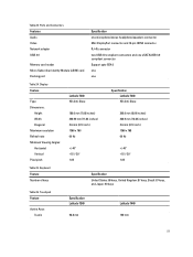
Ports and Connectors Features Audio Video Network adapter USB 3.0 Memory card reader Micro Subscriber Identity Module (uSIM) card Docking port Specification one microphone/stereo headphone/speakers connector Mini DisplayPort connector and 19-pin HDMI connector RJ-45 connector two USB 3.0 compliant connectors and one eSATA/USB 3.0 compliant connector Support upto SD4.0 one one Table 24. Touchpad Feature Active Area: X-axis Specification Latitude 7240 98.8 mm Latitude 7440 100 mm 51 Display Feature Type Dimensions: Height Width...
Ports and Connectors Features Audio Video Network adapter USB 3.0 Memory card reader Micro Subscriber Identity Module (uSIM) card Docking port Specification one microphone/stereo headphone/speakers connector Mini DisplayPort connector and 19-pin HDMI connector RJ-45 connector two USB 3.0 compliant connectors and one eSATA/USB 3.0 compliant connector Support upto SD4.0 one one Table 24. Touchpad Feature Active Area: X-axis Specification Latitude 7240 98.8 mm Latitude 7440 100 mm 51 Display Feature Type Dimensions: Height Width...
Setup and Features Information Tech Sheet
Page 1
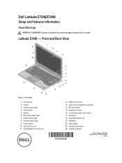
...camera 3. security lock slot 11. audio and microphone connector 14. contactless smart-card reader 17. microphone 2. microphone 5. mini Display Port connector 12. camera status light 4. SD card reader 15. wireless status light 9. USB 3.0 connector 13. touchpad 18. mute button 21. volume up button Regulatory Model: : P22S, P40G Regulatory Type: : P22S001, P40G001 2013- 04 keyboard 20. hard-drive status light 7. volume down button 22. Front View 1. touchpad buttons (2) 19. Latitude E7240 - fingerprint reader 16. display 6. power button 10. battery...
...camera 3. security lock slot 11. audio and microphone connector 14. contactless smart-card reader 17. microphone 2. microphone 5. mini Display Port connector 12. camera status light 4. SD card reader 15. wireless status light 9. USB 3.0 connector 13. touchpad 18. mute button 21. volume up button Regulatory Model: : P22S, P40G Regulatory Type: : P22S001, P40G001 2013- 04 keyboard 20. hard-drive status light 7. volume down button 22. Front View 1. touchpad buttons (2) 19. Latitude E7240 - fingerprint reader 16. display 6. power button 10. battery...
Statement Of Volatility
Page 1
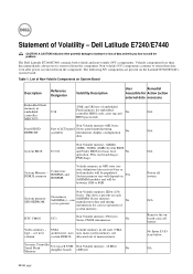
... (NV) components. The following NV components are present on each SoDIMM. Stores memory manufacturer data and timing information for basic boot No operation, PSA (on System Board Description Reference Designator Volatility Description User Remedial Accessible for embedded controller BIOS code, asset tag and No N/A BIOS passwords Non Volatile memory 64K bytes. NA Month yyyy Dell Latitude E7240/E7440 CAUTION: A CAUTION indicates either potential damage to 8GB...
... (NV) components. The following NV components are present on each SoDIMM. Stores memory manufacturer data and timing information for basic boot No operation, PSA (on System Board Description Reference Designator Volatility Description User Remedial Accessible for embedded controller BIOS code, asset tag and No N/A BIOS passwords Non Volatile memory 64K bytes. NA Month yyyy Dell Latitude E7240/E7440 CAUTION: A CAUTION indicates either potential damage to 8GB...
Statement Of Volatility
Page 2
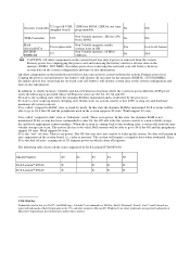
... state is the working state, a restore file from the system. Microsoft®, Windows® are registered trademarks of Dell Inc. S3 is read/write by Dell Latitude E7240/E7440: Model Number Dell Latitude™ E7240 Dell Latitude™ E7440 S0 S1 S3 S4 S5 X X X X X X X X © 2013 Dell Inc. Win8 support S4 state. Secondary power loss (removing the on-board coin-cell battery) destroys system data on the system configuration and time...
... state is the working state, a restore file from the system. Microsoft®, Windows® are registered trademarks of Dell Inc. S3 is read/write by Dell Latitude E7240/E7440: Model Number Dell Latitude™ E7240 Dell Latitude™ E7440 S0 S1 S3 S4 S5 X X X X X X X X © 2013 Dell Inc. Win8 support S4 state. Secondary power loss (removing the on-board coin-cell battery) destroys system data on the system configuration and time...


