
User Manual
Page 2
trackstick 21. device status lights Figure 2. HDMI connector 2. power connector 6. network connector 7. audio connector 10. Do not store your Dell computer in the air vents. Installing the Handle Assembly 1. Insert a paper clip into , or allow dust to unlock and remove the covering plugs from their ... when the computer gets hot. touchpad buttons (2) 18. VGA connector 9. fingerprint reader 15. ExpressCard slot 14. trackstick buttons (3) 20. cooling vents 11. 13. power and battery status lights 5. touchpad 19. Secure Digital (SD) memory-card reader 16.
trackstick 21. device status lights Figure 2. HDMI connector 2. power connector 6. network connector 7. audio connector 10. Do not store your Dell computer in the air vents. Installing the Handle Assembly 1. Insert a paper clip into , or allow dust to unlock and remove the covering plugs from their ... when the computer gets hot. touchpad buttons (2) 18. VGA connector 9. fingerprint reader 15. ExpressCard slot 14. trackstick buttons (3) 20. cooling vents 11. 13. power and battery status lights 5. touchpad 19. Secure Digital (SD) memory-card reader 16.

User Manual
Page 5
... switchable Memory Memory connector Memory capacity Memory type Minimum memory Maximum memory two SODIMM slots 1 GB, 2 GB, or 4 GB DDR3 SDRAM (1333 MHz) 1 GB 8 GB Battery Type Dimensions: • 6-cell "smart" Lithium ion • 9-cell "smart" Lithium ion 5 Specifications NOTE: Offerings may vary by law to view information about your computer...
... switchable Memory Memory connector Memory capacity Memory type Minimum memory Maximum memory two SODIMM slots 1 GB, 2 GB, or 4 GB DDR3 SDRAM (1333 MHz) 1 GB 8 GB Battery Type Dimensions: • 6-cell "smart" Lithium ion • 9-cell "smart" Lithium ion 5 Specifications NOTE: Offerings may vary by law to view information about your computer...

User Manual
Page 6
... Height Width 9-cell Depth Height Width Weight: 6-cell 9-cell Voltage Temperature range: Operating Non-Operating Coin-cell battery AC Adapter Type Input voltage Input current (maximum) Input frequency Output power Output current Rated output voltage 6 48.08 mm (1.89 inches) 20.00 mm (0....
... Height Width 9-cell Depth Height Width Weight: 6-cell 9-cell Voltage Temperature range: Operating Non-Operating Coin-cell battery AC Adapter Type Input voltage Input current (maximum) Input frequency Output power Output current Rated output voltage 6 48.08 mm (1.89 inches) 20.00 mm (0....

User Manual
Page 7
...;C to 40 °C (32 °F to 104 °F) -40 °C to 70 °C (-40 °F to 158 °F) Physical Height Width Depth Weight (with 6-cell battery and air bay) 29.00 mm to 37.70 mm (1.14 inches to 1.48 inches) 357.30 mm (14.07 inches) 246.50 mm (9.70...
...;C to 40 °C (32 °F to 104 °F) -40 °C to 70 °C (-40 °F to 158 °F) Physical Height Width Depth Weight (with 6-cell battery and air bay) 29.00 mm to 37.70 mm (1.14 inches to 1.48 inches) 357.30 mm (14.07 inches) 246.50 mm (9.70...

Owners Manual
Page 3
... Installing The ATG Handle 14 3 ATG Port Cover 15 Removing the ATG Port Cover 15 Installing The ATG Port Cover 16 4 Modem Connector Plug 17 Removing the Modem Connector Plug 17 Installing the Modem Connector Plug 18 5 ExpressCard 19 Removing the ExpressCard 19 Installing the ExpressCard 19 6 Battery...21 Removing the Battery...21 Installing the Battery...22...
... Installing The ATG Handle 14 3 ATG Port Cover 15 Removing the ATG Port Cover 15 Installing The ATG Port Cover 16 4 Modem Connector Plug 17 Removing the Modem Connector Plug 17 Installing the Modem Connector Plug 18 5 ExpressCard 19 Removing the ExpressCard 19 Installing the ExpressCard 19 6 Battery...21 Removing the Battery...21 Installing the Battery...22...

Owners Manual
Page 4
... Network (WWAN) Card 41 Removing the Wireless Wide Area Network (WWAN) Card 41 Installing the Wireless Wide Area Network (WWAN) Card 43 15 Coin-Cell Battery 45 Removing the Coin-Cell Battery 45 Installing the Coin-Cell...
... Network (WWAN) Card 41 Removing the Wireless Wide Area Network (WWAN) Card 41 Installing the Wireless Wide Area Network (WWAN) Card 43 15 Coin-Cell Battery 45 Removing the Coin-Cell Battery 45 Installing the Coin-Cell...

Owners Manual
Page 7
33 Display Panel 113 Removing the Display Panel 113 Installing the Display Panel 115 34 Display Bracket 117 Removing the Display Bracket 117 Installing the Display Bracket 117 35 Camera 119 Removing the Camera 119 Installing the Camera...120 36 Specifications 121 Technical Specifications 121 37 System Setup 129 Setup Overview...129 Entering System Setup 129 System Setup Menu...129 38 Diagnostics 141 Diagnostic LED Codes 141 Battery Status Lights...142 Device Status Lights...143 39 Contacting Dell 145 Contacting Dell...145
33 Display Panel 113 Removing the Display Panel 113 Installing the Display Panel 115 34 Display Bracket 117 Removing the Display Bracket 117 Installing the Display Bracket 117 35 Camera 119 Removing the Camera 119 Installing the Camera...120 36 Specifications 121 Technical Specifications 121 37 System Setup 129 Setup Overview...129 Entering System Setup 129 System Setup Menu...129 38 Diagnostics 141 Diagnostic LED Codes 141 Battery Status Lights...142 Device Status Lights...143 39 Contacting Dell 145 Contacting Dell...145

Owners Manual
Page 10
... outlet before you begin working inside your work surface. NOTE: To avoid damaging the system board, you must remove the main battery before you work, periodically touch an unpainted metal surface to prevent the computer cover from the network device. 4. Remove the main...than shown in this document. Ensure that your computer, ground yourself by touching an unpainted metal surface, such as the optional Media Base or Battery Slice, undock it. CAUTION: Before touching anything inside the computer. 1. Recommended Tools The procedures in this document may require the following steps ...
... outlet before you begin working inside your work surface. NOTE: To avoid damaging the system board, you must remove the main battery before you work, periodically touch an unpainted metal surface to prevent the computer cover from the network device. 4. Remove the main...than shown in this document. Ensure that your computer, ground yourself by touching an unpainted metal surface, such as the optional Media Base or Battery Slice, undock it. CAUTION: Before touching anything inside the computer. 1. Recommended Tools The procedures in this document may require the following steps ...
Owners Manual
Page 11
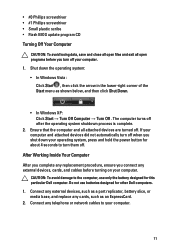
Do not use only the battery designed for other Dell computers. 1. If your computer and attached devices did not automatically turn off when you turn them off . CAUTION: To avoid damage to your computer. • #0 ... , then click the arrow in the lower-right corner of the Start menu as a port replicator, battery slice, or media base, and replace any telephone or network cables to the computer, use batteries designed for this particular Dell computer. Connect any cards, such as an ExpressCard. 2. Connect any external devices, such as shown...
Do not use only the battery designed for other Dell computers. 1. If your computer and attached devices did not automatically turn off when you turn them off . CAUTION: To avoid damage to your computer. • #0 ... , then click the arrow in the lower-right corner of the Start menu as a port replicator, battery slice, or media base, and replace any telephone or network cables to the computer, use batteries designed for this particular Dell computer. Connect any cards, such as an ExpressCard. 2. Connect any external devices, such as shown...

Owners Manual
Page 12
CAUTION: To connect a network cable, first plug the cable into the network device and then plug it into the computer. 3. Turn on your computer and all attached devices to their electrical outlets. 5. Connect your computer. 12 Replace the battery. 4.
CAUTION: To connect a network cable, first plug the cable into the network device and then plug it into the computer. 3. Turn on your computer and all attached devices to their electrical outlets. 5. Connect your computer. 12 Replace the battery. 4.
Owners Manual
Page 17
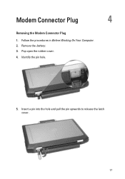
Remove the battery. 3. Pop open the rubber cover. 4. Insert a pin into the hole and pull the pin upwards to release the latch cover. 17 Identify the pin hole. 5. Modem Connector Plug 4 Removing the Modem Connector Plug 1. Follow the procedures in Before Working On Your Computer. 2.
Remove the battery. 3. Pop open the rubber cover. 4. Insert a pin into the hole and pull the pin upwards to release the latch cover. 17 Identify the pin hole. 5. Modem Connector Plug 4 Removing the Modem Connector Plug 1. Follow the procedures in Before Working On Your Computer. 2.

Owners Manual
Page 18
Follow the procedures in After Working Inside Your Computer. 18 6. Installing the Modem Connector Plug 1. Lock the rubber cover. 4. Remove the cover. Place the modem cover. 2. Install the Battery. 5. Identify the pin hole and insert a pin into the hole and pull the pin to lock the cover. 3.
Follow the procedures in After Working Inside Your Computer. 18 6. Installing the Modem Connector Plug 1. Lock the rubber cover. 4. Remove the cover. Place the modem cover. 2. Install the Battery. 5. Identify the pin hole and insert a pin into the hole and pull the pin to lock the cover. 3.

Owners Manual
Page 21
Slide the battery latches toward the unlock position. 3. Battery 6 Removing the Battery 1. Slide the battery out of the computer and remove it. 21 Follow the procedures in Before Working On Your Computer. 2.
Slide the battery latches toward the unlock position. 3. Battery 6 Removing the Battery 1. Slide the battery out of the computer and remove it. 21 Follow the procedures in Before Working On Your Computer. 2.

Owners Manual
Page 22
Follow the procedures in After working inside your computer. 22 Slide the battery into its slot until it clicks into place. 2. Installing the Battery 1.
Follow the procedures in After working inside your computer. 22 Slide the battery into its slot until it clicks into place. 2. Installing the Battery 1.

Owners Manual
Page 23
Remove the SIM card from the system. 23 Insert the SIM card into the slot. 4. Remove the Battery. 3. Follow the procedures in Before Working On Your Computer. 2. Subscriber Identity Module (SIM) Card 7 Removing the Subscriber Identity Module (SIM) Card 1.
Remove the SIM card from the system. 23 Insert the SIM card into the slot. 4. Remove the Battery. 3. Follow the procedures in Before Working On Your Computer. 2. Subscriber Identity Module (SIM) Card 7 Removing the Subscriber Identity Module (SIM) Card 1.

Owners Manual
Page 24
Slide the SIM card into its slot. 2. Installing the Subscriber Identity Module (SIM) Card 1. Follow the procedures in After Working Inside Your Computer. 24 Install the Battery. 3.
Slide the SIM card into its slot. 2. Installing the Subscriber Identity Module (SIM) Card 1. Follow the procedures in After Working Inside Your Computer. 24 Install the Battery. 3.
Owners Manual
Page 27
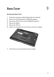
Remove the ATG Port Cover (only for E6420 ATG systems). 3. Base Cover 9 Removing the Base Cover 1. Lift the base cover up and away from the computer. 27 Remove the Battery. 5. Remove the screws that secure the base cover to the computer. 7. Follow the procedures in Before Working On Your Computer. 2. Remove the SD Card. 6. Remove the ATG Handle (only for E6420 ATG systems). 4.
Remove the ATG Port Cover (only for E6420 ATG systems). 3. Base Cover 9 Removing the Base Cover 1. Lift the base cover up and away from the computer. 27 Remove the Battery. 5. Remove the screws that secure the base cover to the computer. 7. Follow the procedures in Before Working On Your Computer. 2. Remove the SD Card. 6. Remove the ATG Handle (only for E6420 ATG systems). 4.

Owners Manual
Page 28
Install the ATG Port Cover (only for E6420 ATG systems). 7. Place the base cover to the computer. 3. Install the Secure Digital (SD) Card. 4. Follow the procedures in After Working Inside Your Computer. 28 Install the Battery. 5. Install the ATG Handle (only for E6420 ATG systems). 6. Installing the Base Cover 1. Tighten the screws that secure the base cover to align the screw holes correctly with the computer. 2.
Install the ATG Port Cover (only for E6420 ATG systems). 7. Place the base cover to the computer. 3. Install the Secure Digital (SD) Card. 4. Follow the procedures in After Working Inside Your Computer. 28 Install the Battery. 5. Install the ATG Handle (only for E6420 ATG systems). 6. Installing the Base Cover 1. Tighten the screws that secure the base cover to align the screw holes correctly with the computer. 2.
Owners Manual
Page 29
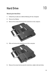
Follow the procedures in Before Working On Your Computer. 2. Remove the screws that secures the hard drive caddy to the computer. 4. Remove the Battery. 3. Slide and remove the hard drive out of the computer. 5. Remove the screw that secure the hard drive to the hard drive. 29 Hard Drive 10 Removing the Hard Drive 1.
Follow the procedures in Before Working On Your Computer. 2. Remove the screws that secures the hard drive caddy to the computer. 4. Remove the Battery. 3. Slide and remove the hard drive out of the computer. 5. Remove the screw that secure the hard drive to the hard drive. 29 Hard Drive 10 Removing the Hard Drive 1.

Owners Manual
Page 30
Replace and tighten the screws that secure the hard drive to the hard drive. 3. 6. Tighten the screw to secure the hard-drive caddy to the computer. 5. Install the Battery. 6. Attach the hard drive caddy to the hard drive. 2. Slide the hard drive into the computer. 4. Installing the Hard Drive 1. Follow the procedures in After working inside your computer. 30 Pull and remove the hard drive caddy away from the hard drive.
Replace and tighten the screws that secure the hard drive to the hard drive. 3. 6. Tighten the screw to secure the hard-drive caddy to the computer. 5. Install the Battery. 6. Attach the hard drive caddy to the hard drive. 2. Slide the hard drive into the computer. 4. Installing the Hard Drive 1. Follow the procedures in After working inside your computer. 30 Pull and remove the hard drive caddy away from the hard drive.

