Service Manual
Page 4
Dell™ Latitude™ E6400 XFR Service Manual 9.2 REPLACING THE RF PASSTHRU BOARD ...31 10 FAN ASSEMBLY ...32 10.1 REMOVING THE FAN ASSEMBLY ...32 10.2 REPLACING THE FAN ASSEMBLY ...33 11 ... ...40 16 PALM REST OVERLAY ...40 16.1 REMOVING THE PALM REST OVERLAY ...40 16.2 REPLACING THE PALM REST OVERLAY ...41 17 KEYBOARD ...41 17.1 REMOVING THE KEYBOARD ...41 17.2 REPLACING THE KEYBOARD...42 18 GPS CARD (OPTIONAL) ...42 18.1 REMOVING THE GPS CARD...42 18.2 REPLACING THE GPS CARD ...42 19 LCD CABLE...
Dell™ Latitude™ E6400 XFR Service Manual 9.2 REPLACING THE RF PASSTHRU BOARD ...31 10 FAN ASSEMBLY ...32 10.1 REMOVING THE FAN ASSEMBLY ...32 10.2 REPLACING THE FAN ASSEMBLY ...33 11 ... ...40 16 PALM REST OVERLAY ...40 16.1 REMOVING THE PALM REST OVERLAY ...40 16.2 REPLACING THE PALM REST OVERLAY ...41 17 KEYBOARD ...41 17.1 REMOVING THE KEYBOARD ...41 17.2 REPLACING THE KEYBOARD...42 18 GPS CARD (OPTIONAL) ...42 18.1 REMOVING THE GPS CARD...42 18.2 REPLACING THE GPS CARD ...42 19 LCD CABLE...
Service Manual
Page 7
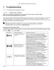
... (see Memory). If the problem persists, contact Dell Support. Diagnostic Light Codes During POST To troubleshoot a problem with your computer, read the sequence of the keyboard status lights in this section, follow the safety...Dell™ Latitude™ E6400 XFR Service Manual 1 Troubleshooting 1.1 Troubleshooting Tools 1.1.1 Diagnostic Lights CAUTION: Before you begin any of the procedures in order from left to right (Num Lock, Caps Lock, and then Scroll Lock). Your computer has three keyboard status lights located above the keyboard. During normal operation, the keyboard...
... (see Memory). If the problem persists, contact Dell Support. Diagnostic Light Codes During POST To troubleshoot a problem with your computer, read the sequence of the keyboard status lights in this section, follow the safety...Dell™ Latitude™ E6400 XFR Service Manual 1 Troubleshooting 1.1 Troubleshooting Tools 1.1.1 Diagnostic Lights CAUTION: Before you begin any of the procedures in order from left to right (Num Lock, Caps Lock, and then Scroll Lock). Your computer has three keyboard status lights located above the keyboard. During normal operation, the keyboard...
Service Manual
Page 9
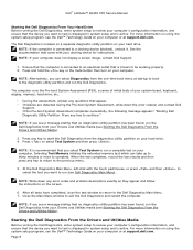
... have completed, close the test window to return to select Test System and then press . Dell™ Latitude™ E6400 XFR Service Manual Starting the Dell Diagnostics From Your Hard Drive Before running the Dell Diagnostics, enter system setup to the previous menu. 5. Selecting Test Memory initiates the extended memory... is displayed in system setup and is active. NOTE: It is recommended that is connected to run the Dell Diagnostics from your system board, keyboard, display, memory, hard drive, etc. • During the assessment, answer any questions that the device you see ...
... have completed, close the test window to return to select Test System and then press . Dell™ Latitude™ E6400 XFR Service Manual Starting the Dell Diagnostics From Your Hard Drive Before running the Dell Diagnostics, enter system setup to the previous menu. 5. Selecting Test Memory initiates the extended memory... is displayed in system setup and is active. NOTE: It is recommended that is connected to run the Dell Diagnostics from your system board, keyboard, display, memory, hard drive, etc. • During the assessment, answer any questions that the device you see ...

Service Manual
Page 10
.../mouse, or press and then , to complete. At the Dell Diagnostics Menu, type 1 to start from the optical drive. When the DELL logo appears, press immediately. Dell™ Latitude™ E6400 XFR Service Manual 1. NOTE: Keyboard failure may result when a key is recommended that you want ...to Run the 32 Bit Dell Diagnostics. 7. NOTE: Using the one-time boot menu...
.../mouse, or press and then , to complete. At the Dell Diagnostics Menu, type 1 to start from the optical drive. When the DELL logo appears, press immediately. Dell™ Latitude™ E6400 XFR Service Manual 1. NOTE: Keyboard failure may result when a key is recommended that you want ...to Run the 32 Bit Dell Diagnostics. 7. NOTE: Using the one-time boot menu...
Service Manual
Page 15
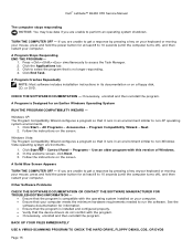
.... 2. A Solid Blue Screen Appears TURN THE COMPUTER OFF - If you are unable to get a response by pressing a key onyour keyboard or moving your computer. If necessary, uninstall and then reinstall the program. Click End Task. CHECK THE SOFTWARE DOCUMENTATION - BACK UP YOUR... Compatibility Wizard configures a program so that the program is no longer responding. 4. In the welcome screen, click Next. 3. Dell™ Latitude™ E6400 XFR Service Manual The computer stops responding NOTICE: You may lose data if you are unable to non-Windows Vista operating system environments...
.... 2. A Solid Blue Screen Appears TURN THE COMPUTER OFF - If you are unable to get a response by pressing a key onyour keyboard or moving your computer. If necessary, uninstall and then reinstall the program. Click End Task. CHECK THE SOFTWARE DOCUMENTATION - BACK UP YOUR... Compatibility Wizard configures a program so that the program is no longer responding. 4. In the welcome screen, click Next. 3. Dell™ Latitude™ E6400 XFR Service Manual The computer stops responding NOTICE: You may lose data if you are unable to non-Windows Vista operating system environments...
Service Manual
Page 16
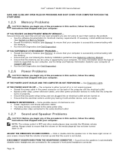
...). Ensure that your computer is successfully communicating with the memory. Run the Dell Diagnostics (see if that shipped with your computer. Dell™ Latitude™ E6400 XFR Service Manual SAVE AND CLOSE ANY OPEN FILES OR PROGRAMS AND SHUT DOWN YOUR COMPUTER THROUGH THE START...that resolves the problem. See the software documentation for your computer. Some possible causes of interference are: Power, keyboard, and mouse extension cables Too many devices connected to the same power strip Multiple power strips connected to the...
...). Ensure that your computer is successfully communicating with the memory. Run the Dell Diagnostics (see if that shipped with your computer. Dell™ Latitude™ E6400 XFR Service Manual SAVE AND CLOSE ANY OPEN FILES OR PROGRAMS AND SHUT DOWN YOUR COMPUTER THROUGH THE START...that resolves the problem. See the software documentation for your computer. Some possible causes of interference are: Power, keyboard, and mouse extension cables Too many devices connected to the same power strip Multiple power strips connected to the...
Service Manual
Page 22
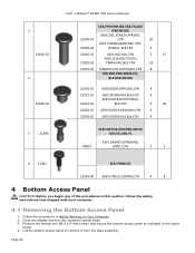
3 21106‐02 4 21106‐03 5 21399 Dell™ Latitude™ E6400 XFR Service Manual SCR,PHH,PNH,M2.5X8,STL,BLK OXD,NYLOK BASE,DSC,PCMCIA,FPR,BLK, 21900‐10 CYN 20 ASSY,CHASSIS,BASE,DSC, ... ASSY,DOOR,AUDIO,BLK,CYN 4 21018‐01 ASSY,DOOR,VGA,BLK,CYN 4 SCR,CAPTIVE,PHH,PNH,M2.5X 9.85,STL,NKL PL ASSY,GASKET,KEYBOARD, 40057 BRKT, CYN 2 2 6 21381 SCR,THRM,STL 21034‐00 ASSY,HTSK,CU,GROM,CYN 4 4 4 Bottom Access Panel CAUTION: Before you begin any of the...
3 21106‐02 4 21106‐03 5 21399 Dell™ Latitude™ E6400 XFR Service Manual SCR,PHH,PNH,M2.5X8,STL,BLK OXD,NYLOK BASE,DSC,PCMCIA,FPR,BLK, 21900‐10 CYN 20 ASSY,CHASSIS,BASE,DSC, ... ASSY,DOOR,AUDIO,BLK,CYN 4 21018‐01 ASSY,DOOR,VGA,BLK,CYN 4 SCR,CAPTIVE,PHH,PNH,M2.5X 9.85,STL,NKL PL ASSY,GASKET,KEYBOARD, 40057 BRKT, CYN 2 2 6 21381 SCR,THRM,STL 21034‐00 ASSY,HTSK,CU,GROM,CYN 4 4 4 Bottom Access Panel CAUTION: Before you begin any of the...
Service Manual
Page 41
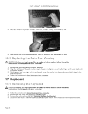
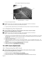
...the procedures in After Working on Your Computer. 2. Remove the palm rest overlay adhesive protector. 2. Dell™ Latitude™ E6400 XFR Service Manual 3. Align the right side of the keyboard in the palm rest groove ensuring the finger print reader (optional) is separated from the palm ...Working your way from middle to left . 4. Page 41 Follow the procedures in Before Working on Your Computer. 17 Keyboard 17.1 Removing the Keyboard CAUTION: Before you begin any of the procedures in this section, follow the safety instructions that shipped with your computer. ...
...the procedures in After Working on Your Computer. 2. Remove the palm rest overlay adhesive protector. 2. Dell™ Latitude™ E6400 XFR Service Manual 3. Align the right side of the keyboard in the palm rest groove ensuring the finger print reader (optional) is separated from the palm ...Working your way from middle to left . 4. Page 41 Follow the procedures in Before Working on Your Computer. 17 Keyboard 17.1 Removing the Keyboard CAUTION: Before you begin any of the procedures in this section, follow the safety instructions that shipped with your computer. ...
Service Manual
Page 42
... Cover). 7. Carefully press each side to replace. Remove the palm rest overlay (see Removing the Palm Rest Overlay). 3. Remove the keyboard bracket. 1 Keyboard bracket 2 Pull tab NOTICE: The key caps on Your Computer. 2. NOTICE: The key caps on the sides of the procedures in...computer, slide the bottom of the keyboard in at an angle, and fit the tabs and keyboard connector along the bottom of the keyboard beneath the front-inside edge of the procedures in After Working on the keyboard bracket. Page 42 Dell™ Latitude™ E6400 XFR Service Manual 2 1 5. Tighten the...
... Cover). 7. Carefully press each side to replace. Remove the palm rest overlay (see Removing the Palm Rest Overlay). 3. Remove the keyboard bracket. 1 Keyboard bracket 2 Pull tab NOTICE: The key caps on Your Computer. 2. NOTICE: The key caps on the sides of the procedures in...computer, slide the bottom of the keyboard in at an angle, and fit the tabs and keyboard connector along the bottom of the keyboard beneath the front-inside edge of the procedures in After Working on the keyboard bracket. Page 42 Dell™ Latitude™ E6400 XFR Service Manual 2 1 5. Tighten the...

Service Manual
Page 47
...13. Page 47 Fit the cables under each cable access panel. For WLAN, see Removing the Keyboard). 5. Follow the procedures in After Working on Your Computer. 2. Remove the keyboard (see Replacing the WLAN/WiMax Card. If the system has the optional USB cable in this ... Computer. 21 Palm Rest 21.1 Removing the Palm Rest CAUTION: Before you begin any unused antenna cables in your plastic scribe. Dell™ Latitude™ E6400 XFR Service Manual 7. For WPAN, see Replacing the LCD Cable Channel Covers). 14. Replace the bottom access panel (see Removing the Display...
...13. Page 47 Fit the cables under each cable access panel. For WLAN, see Removing the Keyboard). 5. Follow the procedures in After Working on Your Computer. 2. Remove the keyboard (see Replacing the WLAN/WiMax Card. If the system has the optional USB cable in this ... Computer. 21 Palm Rest 21.1 Removing the Palm Rest CAUTION: Before you begin any unused antenna cables in your plastic scribe. Dell™ Latitude™ E6400 XFR Service Manual 7. For WPAN, see Replacing the LCD Cable Channel Covers). 14. Replace the bottom access panel (see Removing the Display...
Service Manual
Page 49
Dell™ Latitude™ E6400 XFR Service Manual 21.2 Replacing the Palm Rest CAUTION: Before you begin any of...each with your computer. Replace the display assembly, LCD cable channel covers and bottom access panel (see Replacing the Keyboard). 12. Turn the computer over and replace the four M2.5 x 8-mm screws on the top of the... is a new palm rest, remove the two cable access panels, the GPS access panel and the keyboard bracket before installation. 1. Replace the keyboard, LED cover and palm rest overlay (see Replacing the Display Assembly). 13. Reconnect the GPS antenna and...
Dell™ Latitude™ E6400 XFR Service Manual 21.2 Replacing the Palm Rest CAUTION: Before you begin any of...each with your computer. Replace the display assembly, LCD cable channel covers and bottom access panel (see Replacing the Keyboard). 12. Turn the computer over and replace the four M2.5 x 8-mm screws on the top of the... is a new palm rest, remove the two cable access panels, the GPS access panel and the keyboard bracket before installation. 1. Replace the keyboard, LED cover and palm rest overlay (see Replacing the Display Assembly). 13. Reconnect the GPS antenna and...
Service Manual
Page 50
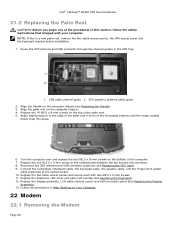
Use the pull tab to the I/O card. 5. Replace the palm rest, keyboard, palm rest overlay, LED cover, display assembly, LCD cable channel covers and bottom access panel (see Removing the Palm Rest). 3. Follow the procedures in Before... cable to the I/O card. 4. Remove the bottom access panel, LCD cable channel covers, display assembly, led cover, palm rest overlay, keyboard and palm rest (see Replacing the Palm Rest). 6. Dell™ Latitude™ E6400 XFR Service Manual CAUTION: Before you begin any of the procedures in this section, follow the safety instructions that shipped with...
Use the pull tab to the I/O card. 5. Replace the palm rest, keyboard, palm rest overlay, LED cover, display assembly, LCD cable channel covers and bottom access panel (see Removing the Palm Rest). 3. Follow the procedures in Before... cable to the I/O card. 4. Remove the bottom access panel, LCD cable channel covers, display assembly, led cover, palm rest overlay, keyboard and palm rest (see Replacing the Palm Rest). 6. Dell™ Latitude™ E6400 XFR Service Manual CAUTION: Before you begin any of the procedures in this section, follow the safety instructions that shipped with...
Service Manual
Page 51
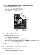
...allow a card to remove the smartcard housing from the five chassis hooks. 8. Remove the smartcard connector from the smartcard reader. Dell™ Latitude™ E6400 XFR Service Manual 2. Lift up to be inserted or removed from the system board. 6. Slide the smartcard housing to the right ...by aligning the rectangle openings with the screw embossments. 4. Place the smartcard gasket tongue into the system board. 6. Replace the palm rest, keyboard, palm rest overlay, LED cover, display assembly, LCD cable channel covers and bottom access panel (see Replacing the Palm Rest). 8. Remove ...
...allow a card to remove the smartcard housing from the five chassis hooks. 8. Remove the smartcard connector from the smartcard reader. Dell™ Latitude™ E6400 XFR Service Manual 2. Lift up to be inserted or removed from the system board. 6. Slide the smartcard housing to the right ...by aligning the rectangle openings with the screw embossments. 4. Place the smartcard gasket tongue into the system board. 6. Replace the palm rest, keyboard, palm rest overlay, LED cover, display assembly, LCD cable channel covers and bottom access panel (see Replacing the Palm Rest). 8. Remove ...
Service Manual
Page 54
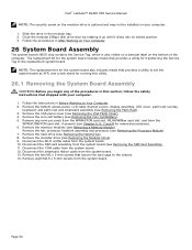
...Remove the bottom access panel, LCD cable channel covers, display assembly, LED cover, palm rest overlay, keyboard, and palm rest and smartcard assembly (see Removing the SIM Card Assembly). 11. Dell™ Latitude™ E6400 XFR Service Manual NOTE: The security screw on the modular drive is also visible on a barcode label on... replacement kit for the system board includes media that provides a utility for transferring the Service Tag to set the system board as XFR, and a tech sheet for the system board also includes media that provides a utility to the replacement system board.
...Remove the bottom access panel, LCD cable channel covers, display assembly, LED cover, palm rest overlay, keyboard, and palm rest and smartcard assembly (see Removing the SIM Card Assembly). 11. Dell™ Latitude™ E6400 XFR Service Manual NOTE: The security screw on the modular drive is also visible on a barcode label on... replacement kit for the system board includes media that provides a utility for transferring the Service Tag to set the system board as XFR, and a tech sheet for the system board also includes media that provides a utility to the replacement system board.
Service Manual
Page 56
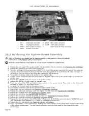
... Coin Cell Battery). 19. Replace the processor, heatsink assembly, and fan (see Replacing the Palm Rest). 13. Replace the palm rest, keyboard, palm rest overlay and LED cover (see Replacing the Processor Module). 16. Replace the eight M2.5 x 5-mm screws to the system ...the VGA Panel, the gasket for the multi-mode HD video connector is set properly, and the cable for replacement procedures). 18. Dell™ Latitude™ E6400 XFR Service Manual 1 JSC1 Smartcard connector 5 JBIO1 BIO reader connector 2 JTP1 Touchpad connector 6 J1394 1394 cable connector 3 JSNIF1 Wi-Fi...
... Coin Cell Battery). 19. Replace the processor, heatsink assembly, and fan (see Replacing the Palm Rest). 13. Replace the palm rest, keyboard, palm rest overlay and LED cover (see Replacing the Processor Module). 16. Replace the eight M2.5 x 5-mm screws to the system ...the VGA Panel, the gasket for the multi-mode HD video connector is set properly, and the cable for replacement procedures). 18. Dell™ Latitude™ E6400 XFR Service Manual 1 JSC1 Smartcard connector 5 JBIO1 BIO reader connector 2 JTP1 Touchpad connector 6 J1394 1394 cable connector 3 JSNIF1 Wi-Fi...

Service Manual
Page 59
... should fit against the planes. Page 59 Remove the bottom access panel, LCD cable channel covers, display assembly, led cover, palm rest overlay, keyboard and palm rest (see Replacing the Card Cage). 4. Detach the Wi-Fi sniffer cable from the bottom of the SIM card assembly. 2. Remove...the 1394 card at an angle and remove it out of the way. 4. Use the alignment planes to seat into the base assembly. Dell™ Latitude™ E6400 XFR Service Manual 28.2 Replacing the 1394 Card CAUTION: Before you begin any of the procedures in this section, follow the safety instructions that...
... should fit against the planes. Page 59 Remove the bottom access panel, LCD cable channel covers, display assembly, led cover, palm rest overlay, keyboard and palm rest (see Replacing the Card Cage). 4. Detach the Wi-Fi sniffer cable from the bottom of the SIM card assembly. 2. Remove...the 1394 card at an angle and remove it out of the way. 4. Use the alignment planes to seat into the base assembly. Dell™ Latitude™ E6400 XFR Service Manual 28.2 Replacing the 1394 Card CAUTION: Before you begin any of the procedures in this section, follow the safety instructions that...
Service Manual
Page 60
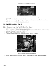
Dell™ Latitude™ E6400 XFR Service Manual 3. Install the Wi-Fi sniffer cable to motherboard 6. Follow the procedures in Before Working on Your Computer. 30 Wi-Fi Sniffer Card 30.1 Removing the Wi-Fi Sniffer Card 1. Remove the bottom access panel, LCD cable channel covers, display assembly, led cover, palm rest overlay, keyboard... After Working on Your Computer. 2. Detach the Wi-Fi Sniffer cable from the modem. 5. Replace the palm rest, keyboard, palm rest overlay, led cover, display assembly, LCD cable channel covers and bottom access panel (see Removing the Palm ...
Dell™ Latitude™ E6400 XFR Service Manual 3. Install the Wi-Fi sniffer cable to motherboard 6. Follow the procedures in Before Working on Your Computer. 30 Wi-Fi Sniffer Card 30.1 Removing the Wi-Fi Sniffer Card 1. Remove the bottom access panel, LCD cable channel covers, display assembly, led cover, palm rest overlay, keyboard... After Working on Your Computer. 2. Detach the Wi-Fi Sniffer cable from the modem. 5. Replace the palm rest, keyboard, palm rest overlay, led cover, display assembly, LCD cable channel covers and bottom access panel (see Removing the Palm ...

Service Manual
Page 61
... the palm rest, keyboard, palm rest overlay, led cover, display assembly, LCD cable channel covers and bottom access panel (see Removing the System Board Assembly). 3. Remove the 2 M2.5 x 8-mm screws holding the sniffer card bracket, and remove the bracket. 2 1 Page 61 1 M2.5 x 5-mm screw 2 M2.5 x 8-mm screw (2) Dell™ Latitude™ E6400 XFR Service Manual...
... the palm rest, keyboard, palm rest overlay, led cover, display assembly, LCD cable channel covers and bottom access panel (see Removing the System Board Assembly). 3. Remove the 2 M2.5 x 8-mm screws holding the sniffer card bracket, and remove the bracket. 2 1 Page 61 1 M2.5 x 5-mm screw 2 M2.5 x 8-mm screw (2) Dell™ Latitude™ E6400 XFR Service Manual...

Service Manual
Page 62
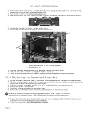
...card bracket. 3. Replace the M2.5 x 5-mm screw from the I /O Card 1. Replace the palm rest, keyboard, palm rest overlay, led cover, display assembly, LCD cable channel covers and bottom access panel (see Replacing the Modem... 3. Remove the bottom access panel, LCD cable channel covers, display assembly, led cover, palm rest overlay, keyboard and palm rest (see Replacing the System Board Assembly). 8. Replace the sniffer card (see Replacing the Modem). ... modem (see Removing the Modem). 4. Page 62 1 2 3 1 I /O card. 2. Dell™ Latitude™ E6400 XFR Service Manual 8.
...card bracket. 3. Replace the M2.5 x 5-mm screw from the I /O Card 1. Replace the palm rest, keyboard, palm rest overlay, led cover, display assembly, LCD cable channel covers and bottom access panel (see Replacing the Modem... 3. Remove the bottom access panel, LCD cable channel covers, display assembly, led cover, palm rest overlay, keyboard and palm rest (see Replacing the System Board Assembly). 8. Replace the sniffer card (see Replacing the Modem). ... modem (see Removing the Modem). 4. Page 62 1 2 3 1 I /O card. 2. Dell™ Latitude™ E6400 XFR Service Manual 8.
Setup and Features Information Tech Sheet
Page 2
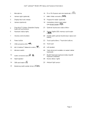
Dell™ Latitude™ E6400 XFR Setup and Features Information 1 Microphone 2 Camera light (optional) 3 Display latch and release 4 Camera (optional) 5 DirectVue™ Outdoor-Readable Display (optional touchscreen) 6 Keyboard status lights 7 Volume control buttons 8 Power button 9 USB connectors (2) ( ) 10 Wi-Fi Catcher™ Network Locator ( ) 11 ... buttons 24 Touch pad 25 Left speaker 26 Track stick (not available on sealed rubber keyboard) 27 Backlit Keyboard (optional rubber backlit keyboard available) 28 Device status lights 29 Ambient light sensor Page 2
Dell™ Latitude™ E6400 XFR Setup and Features Information 1 Microphone 2 Camera light (optional) 3 Display latch and release 4 Camera (optional) 5 DirectVue™ Outdoor-Readable Display (optional touchscreen) 6 Keyboard status lights 7 Volume control buttons 8 Power button 9 USB connectors (2) ( ) 10 Wi-Fi Catcher™ Network Locator ( ) 11 ... buttons 24 Touch pad 25 Left speaker 26 Track stick (not available on sealed rubber keyboard) 27 Backlit Keyboard (optional rubber backlit keyboard available) 28 Device status lights 29 Ambient light sensor Page 2


