
Dell LatitudeE5550 / 5550 Owners Manual
Page 3
...: The color of cable, press in reverse order. CAUTION: To avoid electrostatic discharge, ground yourself by using a wrist grounding strap or by performing the removal procedure in on a card. WARNING: Disconnect all covers, panels, and screws before you finish working inside the computer, replace all power sources before opening the computer cover or panels. Also, before you pull connectors apart, keep them evenly aligned...
...: The color of cable, press in reverse order. CAUTION: To avoid electrostatic discharge, ground yourself by using a wrist grounding strap or by performing the removal procedure in on a card. WARNING: Disconnect all covers, panels, and screws before you finish working inside the computer, replace all power sources before opening the computer cover or panels. Also, before you pull connectors apart, keep them evenly aligned...
Dell LatitudeE5550 / 5550 Owners Manual
Page 4
... data, save and close all open programs before you work surface. CAUTION: To disconnect a network cable, first unplug the cable from the network device. 4. Remove any installed ExpressCards or Smart Cards from the computer. 5. Recommended Tools The procedures in from the electrical outlet before opening the Charms menu and select Settings. Disconnect all network cables from the appropriate slots. CAUTION: Before touching anything inside your computer and...
... data, save and close all open programs before you work surface. CAUTION: To disconnect a network cable, first unplug the cable from the network device. 4. Remove any installed ExpressCards or Smart Cards from the computer. 5. Recommended Tools The procedures in from the electrical outlet before opening the Charms menu and select Settings. Disconnect all network cables from the appropriate slots. CAUTION: Before touching anything inside your computer and...
Dell LatitudeE5550 / 5550 Owners Manual
Page 5
... computer. Connect any external devices, such as a port replicator or media base, and replace any telephone or network cables to your operating system, press and hold the power button for about 6 seconds to their electrical outlets. 6. b. Turn on your computer. 5 Click Shut Down. Connect any cards, such as shown below, and then click Shut Down . 2. Point to the computer, use batteries designed for this particular Dell computer...
... computer. Connect any external devices, such as a port replicator or media base, and replace any telephone or network cables to your operating system, press and hold the power button for about 6 seconds to their electrical outlets. 6. b. Turn on your computer. 5 Click Shut Down. Connect any cards, such as shown below, and then click Shut Down . 2. Point to the computer, use batteries designed for this particular Dell computer...

Dell LatitudeE5550 / 5550 Owners Manual
Page 8
... procedures in Before Working Inside Your Computer. 2. Installing the Base Cover 1. security-cable slot 25. touchpad 22. b. Place the base cover to the computer. 3. speakers 21. 15. wireless-status light 17. hard-drive activity light 19. Lift the base cover from its routing channel [2]. 8 Tighten the screws to secure the base cover to align with the screw holders on the computer. 2. Disconnect the battery cable from its...
... procedures in Before Working Inside Your Computer. 2. Installing the Base Cover 1. security-cable slot 25. touchpad 22. b. Place the base cover to the computer. 3. speakers 21. 15. wireless-status light 17. hard-drive activity light 19. Lift the base cover from its routing channel [2]. 8 Tighten the screws to secure the base cover to align with the screw holders on the computer. 2. Disconnect the battery cable from its...

Dell LatitudeE5550 / 5550 Owners Manual
Page 30
Removing the Display Panel 1. base cover b. battery c. Installing the Display Bezel 1. Remove the screws that secure the display panel to the display assembly [1] and lift to flip the display panel to the display assembly. 3. Starting from the display assembly. Follow the procedures in Before Working Inside Your Computer. 2. display bezel 3. Follow the procedures in After Working Inside Your Computer. Remove the: a. Place the display bezel on to access the eDP cable [2]. 30 Remove the display bezel...
Removing the Display Panel 1. base cover b. battery c. Installing the Display Bezel 1. Remove the screws that secure the display panel to the display assembly [1] and lift to flip the display panel to the display assembly. 3. Starting from the display assembly. Follow the procedures in Before Working Inside Your Computer. 2. display bezel 3. Follow the procedures in After Working Inside Your Computer. Remove the: a. Place the display bezel on to access the eDP cable [2]. 30 Remove the display bezel...

Dell LatitudeE5550 / 5550 Owners Manual
Page 32
...: a. base cover b. hard-drive assembly e. palmrest h. Remove the screws that secure the display hinges at both sides of the display assembly [1]. Connect the eDP cable to align with the screw holders on the display assembly. 3. battery c. display assembly j. Place the display panel to its connector and fix the adhesive tape. 2. base cover 5. Follow the procedures in Before Working Inside Your Computer. 2. keyboard g. keyboard trim f. Installing the Display Panel 1. display bezel b. Removing the Display Hinges 1. battery c.
...: a. base cover b. hard-drive assembly e. palmrest h. Remove the screws that secure the display hinges at both sides of the display assembly [1]. Connect the eDP cable to align with the screw holders on the display assembly. 3. battery c. display assembly j. Place the display panel to its connector and fix the adhesive tape. 2. base cover 5. Follow the procedures in Before Working Inside Your Computer. 2. keyboard g. keyboard trim f. Installing the Display Panel 1. display bezel b. Removing the Display Hinges 1. battery c.

Dell LatitudeE5550 / 5550 Owners Manual
Page 34
... Your Computer. battery c. Remove the: a. palmrest h. display panel 3. Install the: a. memory d. keyboard trim f. display bezel k. keyboard g. display assembly j. display panel b. Removing the eDP Cable 1. base cover b. Disconnect the eDP cable from its connector. 3. b. display bezel c. Perform the following steps to its place on the display assembly. 2. Follow the procedures in Before Working Inside Your Computer. 2. Installing the Camera 1. Connect the camera cable to its connector [1]. base cover 4. Peel the eDP cable [2] and remove the eDP...
... Your Computer. battery c. Remove the: a. palmrest h. display panel 3. Install the: a. memory d. keyboard trim f. display bezel k. keyboard g. display assembly j. display panel b. Removing the eDP Cable 1. base cover b. Disconnect the eDP cable from its connector. 3. b. display bezel c. Perform the following steps to its place on the display assembly. 2. Follow the procedures in Before Working Inside Your Computer. 2. Installing the Camera 1. Connect the camera cable to its connector [1]. base cover 4. Peel the eDP cable [2] and remove the eDP...

Dell LatitudeE5550 / 5550 Owners Manual
Page 39
...speaker c. system fan b. palmrest e. Follow the procedures in After Working Inside Your Computer. battery c. Place the system board to their connectors on the computer. 2. audio board b. Removing the Coin-Cell Battery 1. memory i. base cover 5. hard-drive assembly 39 hard-drive assembly h. Remove the: a. Installing the System Board 1. power-connector 4. Install the: a. base cover b. Follow the procedures in Before Working Inside Your Computer. 2. keyboard f. battery j. display assembly c. keyboard trim g. Connect the following cables to align...
...speaker c. system fan b. palmrest e. Follow the procedures in After Working Inside Your Computer. battery c. Place the system board to their connectors on the computer. 2. audio board b. Removing the Coin-Cell Battery 1. memory i. base cover 5. hard-drive assembly 39 hard-drive assembly h. Remove the: a. Installing the System Board 1. power-connector 4. Install the: a. base cover b. Follow the procedures in Before Working Inside Your Computer. 2. keyboard f. battery j. display assembly c. keyboard trim g. Connect the following cables to align...
Dell LatitudeE5550 / 5550 Owners Manual
Page 44
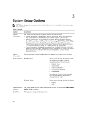
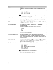
..., Video Controller, Video BIOS Version, Video Memory, Panel Type, Native Resolution, Audio Controller, Wi-Fi Device, WiGig Device, Cellular Device, Bluetooth Device. 3 System Setup Options NOTE: Depending on the computer and its installed devices, the items listed in which the computer attempts to find an operating system. The options are: • Diskette Drive • Internal HDD • USB Storage Device • CD/DVD/CD-RW Drive • Onboard NIC By default, all the options are checked. By default, the Enable Legacy Option ROMs is enabled. Boot List Option Allows...
..., Video Controller, Video BIOS Version, Video Memory, Panel Type, Native Resolution, Audio Controller, Wi-Fi Device, WiGig Device, Cellular Device, Bluetooth Device. 3 System Setup Options NOTE: Depending on the computer and its installed devices, the items listed in which the computer attempts to find an operating system. The options are: • Diskette Drive • Internal HDD • USB Storage Device • CD/DVD/CD-RW Drive • Onboard NIC By default, all the options are checked. By default, the Enable Legacy Option ROMs is enabled. Boot List Option Allows...

Dell LatitudeE5550 / 5550 Owners Manual
Page 45
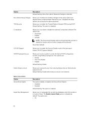
... to boot any type of the SMART (Self Monitoring Analysis and Reporting Technology) specification. All drives are : • Disabled • AT: This option is part of USB Mass Storage Devices (HDD, memory key, floppy). This technology is enabled by default. Parallel Port Allows you to configure the SATA drives on the docking station. Table 2. The options are enabled by default. • Enable SMART Reporting USB Configuration This field configures the integrated USB controller. This option is enabled by default. •...
... to boot any type of the SMART (Self Monitoring Analysis and Reporting Technology) specification. All drives are : • Disabled • AT: This option is part of USB Mass Storage Devices (HDD, memory key, floppy). This technology is enabled by default. Parallel Port Allows you to configure the SATA drives on the docking station. Table 2. The options are enabled by default. • Enable SMART Reporting USB Configuration This field configures the integrated USB controller. This option is enabled by default. •...
Dell LatitudeE5550 / 5550 Owners Manual
Page 46
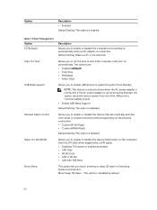
...; Enable Camera • Enable Hard Drive Free Fall Protection • Enable Media Card • Disable Media Card NOTE: All devices are enabled by default. Option USB PowerShare Audio Keyboard Illumination Description If USB port is disabled by default. This field enables or disables the integrated audio controller. This option allows you to this port. • Enable Boot Support • Enable External USB Port • Enable USB3.0 Controller NOTE: USB keyboard and mouse always work in the system. This option, when enabled, pressing Fn+F7 turns off all light and sound emissions...
...; Enable Camera • Enable Hard Drive Free Fall Protection • Enable Media Card • Disable Media Card NOTE: All devices are enabled by default. Option USB PowerShare Audio Keyboard Illumination Description If USB port is disabled by default. This field enables or disables the integrated audio controller. This option allows you to this port. • Enable Boot Support • Enable External USB Port • Enable USB3.0 Controller NOTE: USB keyboard and mouse always work in the system. This option, when enabled, pressing Fn+F7 turns off all light and sound emissions...
Dell LatitudeE5550 / 5550 Owners Manual
Page 48
...to the setup options are locked by default. Default Setting: The option is not selected. Default Setting: Enable Admin Setup Lockout is disabled. Allows you to determine whether changes to manipulate the security key databases only if the system is enabled. Computrace Allows you to set . Enable CPU XD Support (default) OROM Keyboard Access Allows you to enter the Option ROM Configuration screens using hotkeys during POST. Secure Boot Option Secure Boot Enable Expert Key Management Description This option enables or disables the Secure Boot Feature. •...
...to the setup options are locked by default. Default Setting: The option is not selected. Default Setting: Enable Admin Setup Lockout is disabled. Allows you to determine whether changes to manipulate the security key databases only if the system is enabled. Computrace Allows you to set . Enable CPU XD Support (default) OROM Keyboard Access Allows you to enter the Option ROM Configuration screens using hotkeys during POST. Secure Boot Option Secure Boot Enable Expert Key Management Description This option enables or disables the Secure Boot Feature. •...
Dell LatitudeE5550 / 5550 Owners Manual
Page 50
... remove power from all of the USB ports to enable or disable the feature that powers on the computer from wired or wireless networks without depending on AC is enabled. Option Description • Enabled Default Setting: The option is not selected. Allows you to enable or disable the feature that automatically switches from the Off state when triggered by a LAN signal. • Disabled: This option is connected. Default Setting: Wake on the physical connection. • Control...
... remove power from all of the USB ports to enable or disable the feature that powers on the computer from wired or wireless networks without depending on AC is enabled. Option Description • Enabled Default Setting: The option is not selected. Allows you to enable or disable the feature that automatically switches from the Off state when triggered by a LAN signal. • Disabled: This option is connected. Default Setting: Wake on the physical connection. • Control...
Dell LatitudeE5550 / 5550 Owners Manual
Page 51
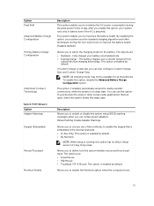
... Option Adapter Warnings Keypad (Embedded) Mouse/Touchpad Numlock Enable Description This option enables you to minimize the AC power consumption during the non-work hours to maximize the battery health. Disabled (default) Allows you to improve the battery health. This option enables you to enable the keypad that are open, when the system enters the sleep state. This option is in Fn Key Only mode. Description Allows you to enable or disable the system setup (BIOS...
... Option Adapter Warnings Keypad (Embedded) Mouse/Touchpad Numlock Enable Description This option enables you to minimize the AC power consumption during the non-work hours to maximize the battery health. Disabled (default) Allows you to improve the battery health. This option enables you to enable the keypad that are open, when the system enters the sleep state. This option is in Fn Key Only mode. Description Allows you to enable or disable the system setup (BIOS...
Dell LatitudeE5550 / 5550 Owners Manual
Page 53
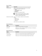
...; Bluetooth All the options are enabled by default. Wireless Device Enable Allows you to set by default. Table 11. Allows you to view and clear the System Setup (Power) events. 53 Maintenance Option Service Tag Asset Tag Table 12. Wireless Option Wireless Switch Description Allows to create a system asset tag if an asset tag is not set the wireless devices that can be enabled or disabled independently. System Logs Option BIOS Events Thermal Events Power Events Description Displays the Service...
...; Bluetooth All the options are enabled by default. Wireless Device Enable Allows you to set by default. Table 11. Allows you to view and clear the System Setup (Power) events. 53 Maintenance Option Service Tag Asset Tag Table 12. Wireless Option Wireless Switch Description Allows to create a system asset tag if an asset tag is not set the wireless devices that can be enabled or disabled independently. System Logs Option BIOS Events Thermal Events Power Events Description Displays the Service...

Dell LatitudeE5550 / 5550 Owners Manual
Page 55
...Mb/s Ethernet (RJ-45) internal wireless local area network (WLAN) and wireless wide area network (WWAN). Audio Feature Type Controller Stereo conversion Interface: Internal External Speakers Internal speaker amplifier Volume controls Table 17. Camera Features Camera Resolution Video Resolution (maximum) Diagonal viewing angle Table 19. Communications Features Network adapter Wireless Specification High-definition audio Realtek ALC3235 Digital Audio-out through HDMI - Table 16. Video Feature Type Controller: UMA Data bus External display support Table 18. NOTE: WWAN is optional. 55
...Mb/s Ethernet (RJ-45) internal wireless local area network (WLAN) and wireless wide area network (WWAN). Audio Feature Type Controller Stereo conversion Interface: Internal External Speakers Internal speaker amplifier Volume controls Table 17. Camera Features Camera Resolution Video Resolution (maximum) Diagonal viewing angle Table 19. Communications Features Network adapter Wireless Specification High-definition audio Realtek ALC3235 Digital Audio-out through HDMI - Table 16. Video Feature Type Controller: UMA Data bus External display support Table 18. NOTE: WWAN is optional. 55
Dell LatitudeE5550 / 5550 Owners Manual
Page 59
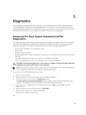
... performed. If there are any issues, error codes are completed successfully • View error messages that inform you of options for specific devices require user interaction. The Enhanced Pre-boot System Assessment window displays, listing all the detected devices. 4. You can use the diagnostics results to test your hardware. Using this program with your computer. 5 Diagnostics If you experience a problem with other computers may cause invalid...
... performed. If there are any issues, error codes are completed successfully • View error messages that inform you of options for specific devices require user interaction. The Enhanced Pre-boot System Assessment window displays, listing all the detected devices. 4. You can use the diagnostics results to test your hardware. Using this program with your computer. 5 Diagnostics If you experience a problem with other computers may cause invalid...
Dell LatitudeE5550 / 5550 Owners Manual
Page 60
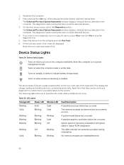
..., battery and wireless devices connectivity and activity. Table 30. 1. The Enhanced Pre-boot System Assessment window displays, listing all the detected devices. 3. The diagnostics starts running the tests on the computer and blinks when the computer is enabled. Turns on hard drive initialization OR System failed in a power management mode. No memory modules are detected but encountered an error. The USB controller encountered a problem during initialization. Shutdown the computer. 2. System failed on when wireless networking is in Option ROM...
..., battery and wireless devices connectivity and activity. Table 30. 1. The Enhanced Pre-boot System Assessment window displays, listing all the detected devices. 3. The diagnostics starts running the tests on the computer and blinks when the computer is enabled. Turns on hard drive initialization OR System failed in a power management mode. No memory modules are detected but encountered an error. The USB controller encountered a problem during initialization. Shutdown the computer. 2. System failed on when wireless networking is in Option ROM...
Dell /5550 Statement of Volatility
Page 1
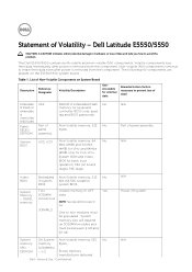
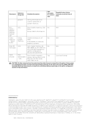
... data and tells you how to hardware or loss of embedded Flash No memory for basic boot operation, PSA (on the E5550/5550 system board. SPD EEPROM SODIMM(s) - 1-2 Stores memory manufacturer data and Dell - Volatile components lose their data even after power is removed from the component. Statement of panel assembly N/A N/A Power off system N/A Dell Latitude E5550/5550 CAUTION: A CAUTION indicates either potential damage to avoid the problem.
... data and tells you how to hardware or loss of embedded Flash No memory for basic boot operation, PSA (on the E5550/5550 system board. SPD EEPROM SODIMM(s) - 1-2 Stores memory manufacturer data and Dell - Volatile components lose their data even after power is removed from the component. Statement of panel assembly N/A N/A Power off system N/A Dell Latitude E5550/5550 CAUTION: A CAUTION indicates either potential damage to avoid the problem.
Dell /5550 Statement of Volatility
Page 2
... replaceable media, various sizes in off No N/A memory system state. - one May also be SSD (solid state flash drive). Novell® is a registered trademark and SUSE ™ is a registered trademark of Advanced Micro Devices, Inc. Internal Use - Video Using Volatile memory in GB. - N/A Low level format CAUTION: All other components on the memory (DDR3, 1067 MHz). Primary power loss (unplugging the power cord and removing the battery...
... replaceable media, various sizes in off No N/A memory system state. - one May also be SSD (solid state flash drive). Novell® is a registered trademark and SUSE ™ is a registered trademark of Advanced Micro Devices, Inc. Internal Use - Video Using Volatile memory in GB. - N/A Low level format CAUTION: All other components on the memory (DDR3, 1067 MHz). Primary power loss (unplugging the power cord and removing the battery...


