Setup and Features Information Tech Sheet
Page 1
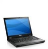
... 2 camera status LED (optional) 3 display latch release switch 4 camera (optional) 5 display latch 6 display 7 volume control buttons 8 power button 9 right speaker 10 modem connector (optional) 11 network connector 12 USB 2.0 connectors (2) 13 optical drive 14 optical drive eject button 15 fingerprint reader (optional) 16 keyboard 17 touchpad buttons 18 wireless switch 19 touchpad 20 trackstick and trackstick buttons (optional) 21 left speaker 22 device status lights 23 keyboard status lights Regulatory Models: P06G and P05F Regulatory Types: P06G001 and P05F001 May 2010 Latitude E5410 -
... 2 camera status LED (optional) 3 display latch release switch 4 camera (optional) 5 display latch 6 display 7 volume control buttons 8 power button 9 right speaker 10 modem connector (optional) 11 network connector 12 USB 2.0 connectors (2) 13 optical drive 14 optical drive eject button 15 fingerprint reader (optional) 16 keyboard 17 touchpad buttons 18 wireless switch 19 touchpad 20 trackstick and trackstick buttons (optional) 21 left speaker 22 device status lights 23 keyboard status lights Regulatory Models: P06G and P05F Regulatory Types: P06G001 and P05F001 May 2010 Latitude E5410 -

Setup and Features Information Tech Sheet
Page 3
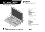
... 20 19 18 17 16 8 9 10 14 15 11 12 13 1 display latch 2 built-in microphone 3 camera status LED (optional) 4 display latch release switch 5 camera (optional) 6 display 7 display latch 8 volume control buttons 9 power button 10 right speaker 11 serial connector 12 USB 2.0 connectors (2) 13 network connector 14 optical drive 15 optical drive eject button 16 fingerprint reader (optional) 17 keyboard 18 touchpad buttons 19 wireless switch 20 touchpad 21 trackstick and trackstick buttons (optional) 22 left speaker 23 device status lights 24 keyboard status lights Latitude E5510 -
... 20 19 18 17 16 8 9 10 14 15 11 12 13 1 display latch 2 built-in microphone 3 camera status LED (optional) 4 display latch release switch 5 camera (optional) 6 display 7 display latch 8 volume control buttons 9 power button 10 right speaker 11 serial connector 12 USB 2.0 connectors (2) 13 network connector 14 optical drive 15 optical drive eject button 16 fingerprint reader (optional) 17 keyboard 18 touchpad buttons 19 wireless switch 20 touchpad 21 trackstick and trackstick buttons (optional) 22 left speaker 23 device status lights 24 keyboard status lights Latitude E5510 -
Setup and Features Information Tech Sheet
Page 5
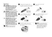
..., see www.dell.com/regulatory_compliance. Using an incompatible cable or improperly connecting the cable to the power strip or electrical outlet may not be included if you did not order them. 1 Connect the AC adapter to the AC adapter connector on the portable computer and to the electrical outlet. 3 Connect USB devices, such as a mouse or a keyboard (optional). 5 Open the computer display and press the power button to turn on the...
..., see www.dell.com/regulatory_compliance. Using an incompatible cable or improperly connecting the cable to the power strip or electrical outlet may not be included if you did not order them. 1 Connect the AC adapter to the AC adapter connector on the portable computer and to the electrical outlet. 3 Connect USB devices, such as a mouse or a keyboard (optional). 5 Open the computer display and press the power button to turn on the...
Service Manual
Page 1
...; Windows® operating systems are not applicable. CAUTION: A CAUTION indicates potential damage to change without the written permission of Intel Corporation; WARNING: A WARNING indicates a potential for property damage, personal injury, or death. All rights reserved. disclaims any manner whatsoever without notice. © 2010 Dell Inc. Dell™ Latitude™ E5410 Discrete Service Manual Working on Your Computer Adding and Replacing Parts Specifications Diagnostics System Setup Notes...
...; Windows® operating systems are not applicable. CAUTION: A CAUTION indicates potential damage to change without the written permission of Intel Corporation; WARNING: A WARNING indicates a potential for property damage, personal injury, or death. All rights reserved. disclaims any manner whatsoever without notice. © 2010 Dell Inc. Dell™ Latitude™ E5410 Discrete Service Manual Working on Your Computer Adding and Replacing Parts Specifications Diagnostics System Setup Notes...
Service Manual
Page 4
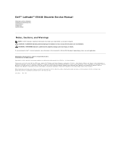
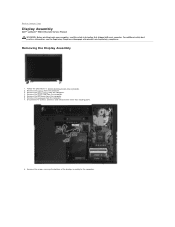
.... 3. Remove the battery from the computer. 5. Back to the computer. Removing the Display Assembly 1. Remove the keyboard from the computer. 4. Remove the access panel from the computer. 7. For additional safety best practices information, see the Regulatory Compliance Homepage at www.dell.com/regulatory_compliance. Remove the screws securing the bottom of the display assembly to Contents Page Display Assembly Dell™ Latitude™ E5410 Discrete Service Manual WARNING: Before working...
.... 3. Remove the battery from the computer. 5. Back to the computer. Removing the Display Assembly 1. Remove the keyboard from the computer. 4. Remove the access panel from the computer. 7. For additional safety best practices information, see the Regulatory Compliance Homepage at www.dell.com/regulatory_compliance. Remove the screws securing the bottom of the display assembly to Contents Page Display Assembly Dell™ Latitude™ E5410 Discrete Service Manual WARNING: Before working...
Service Manual
Page 11
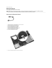
Remove the battery from the computer. 5. Remove the optical drive from the computer. 3. Remove the keyboard from the computer. 8. Back to Contents Page Bluetooth Board Dell™ Latitude™ E5410 Discrete Service Manual WARNING: Before working inside your computer, read the safety information that shipped with your computer. For additional safety best practices information, see the Regulatory Compliance Homepage at www.dell.com/regulatory_compliance. Removing the Bluetooth Board 1. Remove the...
Remove the battery from the computer. 5. Remove the optical drive from the computer. 3. Remove the keyboard from the computer. 8. Back to Contents Page Bluetooth Board Dell™ Latitude™ E5410 Discrete Service Manual WARNING: Before working inside your computer, read the safety information that shipped with your computer. For additional safety best practices information, see the Regulatory Compliance Homepage at www.dell.com/regulatory_compliance. Removing the Bluetooth Board 1. Remove the...
Service Manual
Page 13
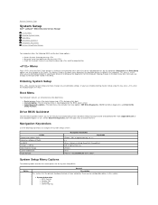
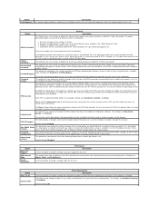
... Tag Making changes in the computer. l Added diagnostics options-The boot menu now includes two new options: IDE Drive Diagnostics (90/90 hard drive diagnostics) and Boot to change Cancel modification Reset defaults Navigation Keystrokes , left- Option General Description This section lists the primary hardware features of the valid boot devices for the System Setup BIOS. Drive BIOS Quicktest The Drive BIOS Quicktest allows you have trouble entering System Setup using this key, press when the keyboard lights first flash. Navigation Keystrokes Use the...
... Tag Making changes in the computer. l Added diagnostics options-The boot menu now includes two new options: IDE Drive Diagnostics (90/90 hard drive diagnostics) and Boot to change Cancel modification Reset defaults Navigation Keystrokes , left- Option General Description This section lists the primary hardware features of the valid boot devices for the System Setup BIOS. Drive BIOS Quicktest The Drive BIOS Quicktest allows you have trouble entering System Setup using this key, press when the keyboard lights first flash. Navigation Keystrokes Use the...
Service Manual
Page 14
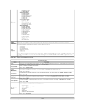
... Panel Type ¡ Native Resolution ¡ Audio Controller ¡ Modem Controller ¡ Wi-Fi Device ¡ Cellular Device ¡ Bluetooth Device Battery Information Indicates the primary battery and the media bay battery status. This is also where the UEFI boot option can also be enabled or disabled. Default setting: Enabled w/PXE Controls system management mechanism. Default setting: COM1 This option configures the operating mode of AC adapter connected to boot from the list using the checkboxes. Option NOTE: Integrated NIC System Management Parallel Port Serial...
... Panel Type ¡ Native Resolution ¡ Audio Controller ¡ Modem Controller ¡ Wi-Fi Device ¡ Cellular Device ¡ Bluetooth Device Battery Information Indicates the primary battery and the media bay battery status. This is also where the UEFI boot option can also be enabled or disabled. Default setting: Enabled w/PXE Controls system management mechanism. Default setting: COM1 This option configures the operating mode of AC adapter connected to boot from the list using the checkboxes. Option NOTE: Integrated NIC System Management Parallel Port Serial...
Service Manual
Page 15
... Password l Restricts changes to the settings in the TPM to power up from entering Setup when an Admin password is enabled (checkbox filled), the available settings are Deactivate, Disable, and Activate. When enabled (check box filled), the BIOS will not execute any , when you activate or disable the BIOS module interface of the processor. Default setting: Disabled Option Multi Core Support HDD Acoustic Mode Intel® SpeedStep Performance Description Use the checkbox to the owner and...
... Password l Restricts changes to the settings in the TPM to power up from entering Setup when an Admin password is enabled (checkbox filled), the available settings are Deactivate, Disable, and Activate. When enabled (check box filled), the BIOS will not execute any , when you activate or disable the BIOS module interface of the processor. Default setting: Disabled Option Multi Core Support HDD Acoustic Mode Intel® SpeedStep Performance Description Use the checkbox to the owner and...
Service Manual
Page 16
... integrated touchpad enabled when an external PS/2 mouse is present. Boot quickly unless the BIOS has been updated, memory changed, or the previous POST did not complete. Allow the operating system to control this setting (this feature. The factory default setting is Disabled. The factory default setting is Enabled. Does not allow the system to power on when it will charge. ExpressCharge Standard = The battery will only emulate the key in the operating system. The BIOS displays these...
... integrated touchpad enabled when an external PS/2 mouse is present. Boot quickly unless the BIOS has been updated, memory changed, or the previous POST did not complete. Allow the operating system to control this setting (this feature. The factory default setting is Disabled. The factory default setting is Enabled. Does not allow the system to power on when it will charge. ExpressCharge Standard = The battery will only emulate the key in the operating system. The BIOS displays these...

Service Manual
Page 17
... Page Thermal Events This field allows you to view and clear BIOS POST events. Asset Tag This field allows you can only be updated if the Asset Tag is not already set , you to create a system Asset Tag. Option Wireless Switch Wireless Devices Enable Wireless Description Use the checkboxes to determine which wireless devices will be prompted to enter the Service Tag. The available options are Internal WWAN and Bluetooth.
... Page Thermal Events This field allows you to view and clear BIOS POST events. Asset Tag This field allows you can only be updated if the Asset Tag is not already set , you to create a system Asset Tag. Option Wireless Switch Wireless Devices Enable Wireless Description Use the checkboxes to determine which wireless devices will be prompted to enter the Service Tag. The available options are Internal WWAN and Bluetooth.
Service Manual
Page 18
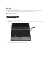
Remove the battery. 3. Gently pry along the edge of the computer, use a flat-bladed screwdriver or spudger (inserted into the notch) to pry up the LED cover. 4. Back to release it from the latches and remove. For additional safety best practices ... angle. Follow the procedures in Before Working Inside Your Computer. 2. Open the display at www.dell.com/regulatory_compliance. Removing the LED Cover 1. On the right side of the LED cover to Contents Page LED Cover Dell™ Latitude™ E5410 Discrete Service Manual WARNING: Before working inside your computer, read the safety ...
Remove the battery. 3. Gently pry along the edge of the computer, use a flat-bladed screwdriver or spudger (inserted into the notch) to pry up the LED cover. 4. Back to release it from the latches and remove. For additional safety best practices ... angle. Follow the procedures in Before Working Inside Your Computer. 2. Open the display at www.dell.com/regulatory_compliance. Removing the LED Cover 1. On the right side of the LED cover to Contents Page LED Cover Dell™ Latitude™ E5410 Discrete Service Manual WARNING: Before working inside your computer, read the safety ...
Service Manual
Page 22
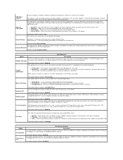
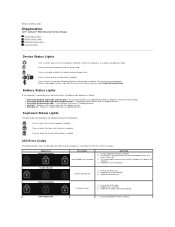
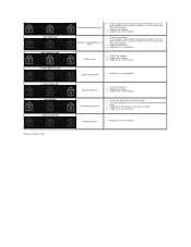
... : Turns on when the Scroll Lock function is attached to indicate battery charge status. Appearance ON-FLASH-FLASH Description No SODIMMs are installed Next Step 1. Replace the video card/system board. Reseat the LCD cable. 2. An unauthenticated or unsupported non-Dell AC adapter is enabled. Temporary battery failure with AC adapter present. l Light off only the Bluetooth wireless technology function, right-click the icon in a no-Power On Self Test (POST) situation. FLASH-ON-ON System board error 1. Install compatible memory modules.
... : Turns on when the Scroll Lock function is attached to indicate battery charge status. Appearance ON-FLASH-FLASH Description No SODIMMs are installed Next Step 1. Replace the video card/system board. Reseat the LCD cable. 2. An unauthenticated or unsupported non-Dell AC adapter is enabled. Temporary battery failure with AC adapter present. l Light off only the Bluetooth wireless technology function, right-click the icon in a no-Power On Self Test (POST) situation. FLASH-ON-ON System board error 1. Install compatible memory modules.
Service Manual
Page 23
...installed, remove one and test. Test the other module in the same slot and test. Reseat the modem. 2. Replace the modem. 3. Replace the device. 3. Test the computer with both modules. 3. Video card error 1. Reseat the device. 2. Replace the system board. Replace the device that is detected but has errors 1. Reseat the hard drive and optical drive. 2. Reseat the memory. 2. Replace the memory. 4. Storage device error 1. Replace the system board. Replace the memory. 4. Replace the system board. ON-FLASH-ON OFF-FLASH-FLASH FLASH-FLASH-FLASH...
...installed, remove one and test. Test the other module in the same slot and test. Reseat the modem. 2. Replace the modem. 3. Replace the device. 3. Test the computer with both modules. 3. Video card error 1. Reseat the device. 2. Replace the system board. Replace the device that is detected but has errors 1. Reseat the hard drive and optical drive. 2. Reseat the memory. 2. Replace the memory. 4. Storage device error 1. Replace the system board. Replace the memory. 4. Replace the system board. ON-FLASH-ON OFF-FLASH-FLASH FLASH-FLASH-FLASH...
Service Manual
Page 26
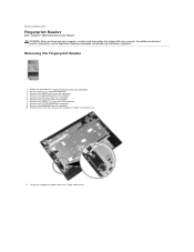
... Reader 1. Remove the LED cover from the computer. 8. Remove the display assembly from the computer. 6. Remove the LED board from the computer. 3. Remove the screw that secures the fingerprint reader to Contents Page Fingerprint Reader Dell™ Latitude™ E5410 Discrete Service Manual WARNING: Before working inside your computer, read the safety information that shipped with your computer. Remove the battery from the computer. 9. Remove the access panel from the computer. 5. Remove the optical drive...
... Reader 1. Remove the LED cover from the computer. 8. Remove the display assembly from the computer. 6. Remove the LED board from the computer. 3. Remove the screw that secures the fingerprint reader to Contents Page Fingerprint Reader Dell™ Latitude™ E5410 Discrete Service Manual WARNING: Before working inside your computer, read the safety information that shipped with your computer. Remove the battery from the computer. 9. Remove the access panel from the computer. 5. Remove the optical drive...
Service Manual
Page 36
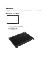
.... 7. Remove the keyboard from the computer. 3. Remove the screws securing the display bezel to Contents Page Display Bezel Dell™ Latitude™ E5410 Discrete Service Manual WARNING: Before working inside your computer, read the safety information that shipped with your computer. For additional safety best practices information, see the Regulatory Compliance Homepage at www.dell.com/regulatory_compliance. Remove the access panel from the computer. 6. Remove the LED cover...
.... 7. Remove the keyboard from the computer. 3. Remove the screws securing the display bezel to Contents Page Display Bezel Dell™ Latitude™ E5410 Discrete Service Manual WARNING: Before working inside your computer, read the safety information that shipped with your computer. For additional safety best practices information, see the Regulatory Compliance Homepage at www.dell.com/regulatory_compliance. Remove the access panel from the computer. 6. Remove the LED cover...
Service Manual
Page 39
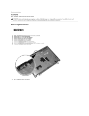
... the Regulatory Compliance Homepage at www.dell.com/regulatory_compliance. Remove the display panel, bracket and hinges from the computer. 8. Lift up the display camera and remove. Remove the LED cover from the computer. 3. Removing the Camera 1. Remove the battery from the computer. 6. Remove the keyboard from the computer. 4. Remove the access panel from the computer. 7. Remove the WLAN card from the display assembly. 9. Disconnect the display camera data cable. 11. Remove the display bezel from the computer. 5.
... the Regulatory Compliance Homepage at www.dell.com/regulatory_compliance. Remove the display panel, bracket and hinges from the computer. 8. Lift up the display camera and remove. Remove the LED cover from the computer. 3. Removing the Camera 1. Remove the battery from the computer. 6. Remove the keyboard from the computer. 4. Remove the access panel from the computer. 7. Remove the WLAN card from the display assembly. 9. Disconnect the display camera data cable. 11. Remove the display bezel from the computer. 5.
Service Manual
Page 70
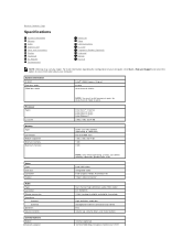
... and digital-to-analog) high definition audio bus microphone-in/line-in pairs for dual-channel mode to work. For more information regarding the configuration of your computer, click Start® Help and Support and select the option to Contents Page Specifications System Information Memory Audio ExpressCard Ports and Connectors Display Touchpad AC Adapter Environmental Processor Video Communications PC Card Fingerprint Reader (Optional) Keyboard Battery Physical NOTE: Offerings may vary by...
... and digital-to-analog) high definition audio bus microphone-in/line-in pairs for dual-channel mode to work. For more information regarding the configuration of your computer, click Start® Help and Support and select the option to Contents Page Specifications System Information Memory Audio ExpressCard Ports and Connectors Display Touchpad AC Adapter Environmental Processor Video Communications PC Card Fingerprint Reader (Optional) Keyboard Battery Physical NOTE: Offerings may vary by...
Service Manual
Page 78
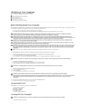
... the removal procedure in this document. To avoid damaging your work surface is not covered by the online or telephone service and support team. If the computer is connected to a docking device (docked) such as a connector on a flat work , periodically touch an unpainted metal surface to avoid bending any installed ExpressCards or Smart Cards from the electrical outlet before opening the display. Turn the...
... the removal procedure in this document. To avoid damaging your work surface is not covered by the online or telephone service and support team. If the computer is connected to a docking device (docked) such as a connector on a flat work , periodically touch an unpainted metal surface to avoid bending any installed ExpressCards or Smart Cards from the electrical outlet before opening the display. Turn the...

Service Manual
Page 79
... computer turns off . Connect any external devices, such as a port replicator, battery slice, or media base, and replace any replacement procedure, ensure you shut down your computer. Turn on your operating system, press and hold the power button for other Dell computers. 1. Connect any external devices, cards, and cables before turning on your computer and all attached devices are turned off after the operating system shutdown process is complete. 2. l In Windows Vista®: Click Start , then...
... computer turns off . Connect any external devices, such as a port replicator, battery slice, or media base, and replace any replacement procedure, ensure you shut down your computer. Turn on your operating system, press and hold the power button for other Dell computers. 1. Connect any external devices, cards, and cables before turning on your computer and all attached devices are turned off after the operating system shutdown process is complete. 2. l In Windows Vista®: Click Start , then...


