
Quick Reference Guide
Page 6
... Windows® License These labels are located on your computer. • Use the Service Tag to identify your computer when you use support.dell.com or contact support. • Enter the Express Service Code to troubleshoot and solve problems • Service Tag and Express Service Code &#...Center 1 Click Start or → Help and Support→ Dell User and System Guides→ System Guides. 2 Click the User's Guide for your call when contacting support. What Are You Looking For? • How to remove and replace parts • Specifications • How to configure system settings •...
... Windows® License These labels are located on your computer. • Use the Service Tag to identify your computer when you use support.dell.com or contact support. • Enter the Express Service Code to troubleshoot and solve problems • Service Tag and Express Service Code &#...Center 1 Click Start or → Help and Support→ Dell User and System Guides→ System Guides. 2 Click the User's Guide for your call when contacting support. What Are You Looking For? • How to remove and replace parts • Specifications • How to configure system settings •...
User's Guide
Page 10
... Windows Vista 144 Restoring Your Operating System 144 Using Microsoft® Windows® System Restore 145 Using the Operating System Media 146 15 Adding and Replacing Parts 149 Before You Begin 149 Recommended Tools 149 Turning Off Your Computer 149 Before Working Inside Your Computer 150 Hinge Cover 152 Keyboard 153 Internal...
... Windows Vista 144 Restoring Your Operating System 144 Using Microsoft® Windows® System Restore 145 Using the Operating System Media 146 15 Adding and Replacing Parts 149 Before You Begin 149 Recommended Tools 149 Turning Off Your Computer 149 Before Working Inside Your Computer 150 Hinge Cover 152 Keyboard 153 Internal...
User's Guide
Page 149
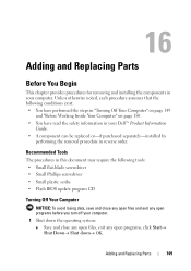
...Dell™ Product Information Guide. • A component can be replaced or-if purchased separately-installed by performing the removal procedure in your computer. 1 Shut down the operating system: a Save and close any open files, exit any open programs, click Start→ Shut Down→ Shut down→ ΟΚ. Adding and Replacing Parts... 149 16 Adding and Replacing Parts Before You Begin This chapter provides procedures for removing and installing the components in reverse order....
...Dell™ Product Information Guide. • A component can be replaced or-if purchased separately-installed by performing the removal procedure in your computer. 1 Shut down the operating system: a Save and close any open files, exit any open programs, click Start→ Shut Down→ Shut down→ ΟΚ. Adding and Replacing Parts... 149 16 Adding and Replacing Parts Before You Begin This chapter provides procedures for removing and installing the components in reverse order....

User's Guide
Page 150
... in the Product Information Guide. NOTICE: To disconnect a network cable, first unplug the cable from potential damage and to servicing that is not authorized by Dell is not covered by your computer and then unplug it . if you begin any attached devices are turned off. Before Working Inside Your Computer Use... being scratched. 2 Turn off when you pull connectors apart, keep them evenly aligned to a docking device (docked), undock it from the computer. 150 Adding and Replacing Parts
... in the Product Information Guide. NOTICE: To disconnect a network cable, first unplug the cable from potential damage and to servicing that is not authorized by Dell is not covered by your computer and then unplug it . if you begin any attached devices are turned off. Before Working Inside Your Computer Use... being scratched. 2 Turn off when you pull connectors apart, keep them evenly aligned to a docking device (docked), undock it from the computer. 150 Adding and Replacing Parts

User's Guide
Page 151
... their electrical outlets. 8 Remove the battery (see "Replacing the Battery" on page 47). 9 Press the power button to ground the system board. 10 Remove any installed PC Cards from the PC Card slot (see "Removing a Card or Blank" on a flat work surface. Adding and Replacing Parts 151 5 Close the display and turn the...
... their electrical outlets. 8 Remove the battery (see "Replacing the Battery" on page 47). 9 Press the power button to ground the system board. 10 Remove any installed PC Cards from the PC Card slot (see "Removing a Card or Blank" on a flat work surface. Adding and Replacing Parts 151 5 Close the display and turn the...

User's Guide
Page 152
... cover away from the computer going from the right toward the left, and lay the cover aside. 4 To replace the hinge cover, insert the left edge of the cover into place. 152 Adding and Replacing Parts NOTICE: To avoid electrostatic discharge, ground yourself by using a wrist grounding strap or by periodically touching an...
... cover away from the computer going from the right toward the left, and lay the cover aside. 4 To replace the hinge cover, insert the left edge of the cover into place. 152 Adding and Replacing Parts NOTICE: To avoid electrostatic discharge, ground yourself by using a wrist grounding strap or by periodically touching an...

User's Guide
Page 153
... surface (such as the back panel) on page 152). 1 2 3 4 5 6 1 screws (3) 2 keyboard tabs (5) 3 palm rest 4 pull-tab 5 keyboard-cable locking arm 6 keyboard cable connector Adding and Replacing Parts 153 5 Press from left to right until the cover snaps into place.
... surface (such as the back panel) on page 152). 1 2 3 4 5 6 1 screws (3) 2 keyboard tabs (5) 3 palm rest 4 pull-tab 5 keyboard-cable locking arm 6 keyboard cable connector Adding and Replacing Parts 153 5 Press from left to right until the cover snaps into place.
User's Guide
Page 154
NOTE: When you replace the keyboard, ensure that you do not pull on the keyboard cable. 4 Rotate the keyboard up on the pull-tab to ensure that the keyboard ... on the keyboard are completely in "Before You Begin" on page 149. 2 Remove the hinge cover (see "Hinge Cover" on page 152). 154 Adding and Replacing Parts NOTE: Lift the keyboard carefully in step 4 to disconnect the keyboard cable connector from the keyboard connector on the system board. If you begin working...
NOTE: When you replace the keyboard, ensure that you do not pull on the keyboard cable. 4 Rotate the keyboard up on the pull-tab to ensure that the keyboard ... on the keyboard are completely in "Before You Begin" on page 149. 2 Remove the hinge cover (see "Hinge Cover" on page 152). 154 Adding and Replacing Parts NOTE: Lift the keyboard carefully in step 4 to disconnect the keyboard cable connector from the keyboard connector on the system board. If you begin working...

User's Guide
Page 155
Adding and Replacing Parts 155 1 2 3 1 card cable 2 card 3 metal tab NOTICE: Be careful when removing the card to avoid damaging the card, card cable, or surrounding components. 3 Carefully remove the card cable from its routing guide. 4 While grasping the card cable with one hand, use a plastic scribe to gently pry the card out from underneath the metal tab with the other hand. 5 Lift the card from the compartment, ensuring that you do not pull on the card cable with excessive force.
Adding and Replacing Parts 155 1 2 3 1 card cable 2 card 3 metal tab NOTICE: Be careful when removing the card to avoid damaging the card, card cable, or surrounding components. 3 Carefully remove the card cable from its routing guide. 4 While grasping the card cable with one hand, use a plastic scribe to gently pry the card out from underneath the metal tab with the other hand. 5 Lift the card from the compartment, ensuring that you do not pull on the card cable with excessive force.
User's Guide
Page 156
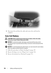
... the computer. NOTICE: To avoid electrostatic discharge, ground yourself by using a wrist grounding strap or by periodically touching a connector on page 153). 156 Adding and Replacing Parts NOTICE: To avoid damaging the system board, you must remove the main battery before you begin working inside the computer. 1 Follow the procedures in your...
... the computer. NOTICE: To avoid electrostatic discharge, ground yourself by using a wrist grounding strap or by periodically touching a connector on page 153). 156 Adding and Replacing Parts NOTICE: To avoid damaging the system board, you must remove the main battery before you begin working inside the computer. 1 Follow the procedures in your...
User's Guide
Page 157
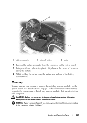
Memory You can increase your computer. CAUTION: Before you begin any of the battery compartment. Adding and Replacing Parts 157 1 2 3 1 battery connector 2 coin-cell battery 3 mylar 4 Remove the battery connector from the connector on the system board. See "Specifications" on page 183 for your ...
Memory You can increase your computer. CAUTION: Before you begin any of the battery compartment. Adding and Replacing Parts 157 1 2 3 1 battery connector 2 coin-cell battery 3 mylar 4 Remove the battery connector from the connector on the system board. See "Specifications" on page 183 for your ...
User's Guide
Page 158
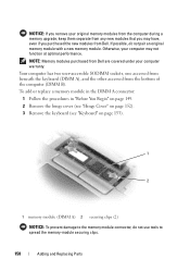
... on page 153). 1 2 1 memory module (DIMM A) 2 securing clips (2) NOTICE: To prevent damage to spread the memory-module securing clips. 158 Adding and Replacing Parts NOTE: Memory modules purchased from the bottom of the computer (DIMM B). Otherwise, your computer may have, even if you may not function at optimal performance... from the computer during a memory upgrade, keep them separate from any new modules that you purchased the new modules from Dell. If possible, do not use tools to the memory module connector, do not pair an original memory module with a new memory module.
... on page 153). 1 2 1 memory module (DIMM A) 2 securing clips (2) NOTICE: To prevent damage to spread the memory-module securing clips. 158 Adding and Replacing Parts NOTE: Memory modules purchased from the bottom of the computer (DIMM B). Otherwise, your computer may have, even if you may not function at optimal performance... from the computer during a memory upgrade, keep them separate from any new modules that you purchased the new modules from Dell. If possible, do not use tools to the memory module connector, do not pair an original memory module with a new memory module.
User's Guide
Page 159
... to carefully spread apart the securing clips on each end of the memory module connector until it . b Slide the module firmly into place. Adding and Replacing Parts 159 No error message indicates this failure. a Align the notch in the module connector with the tab in the connector slot.
... to carefully spread apart the securing clips on each end of the memory module connector until it . b Slide the module firmly into place. Adding and Replacing Parts 159 No error message indicates this failure. a Align the notch in the module connector with the tab in the connector slot.

User's Guide
Page 160
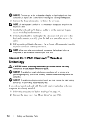
Insert memory modules at a 45-degree angle to install memory modules in two connectors, install a memory module in the connector labeled "DIMMA" before you need to avoid damaging the connector. 1 Follow the procedures in "Before You Begin" on page 149. 2 Turn the computer bottom-side up, loosen the captive screw in the connector labeled "DIMMB." To add or replace a memory module in the DIMM B connector: NOTICE: If you install a module in the memory module cover, and then remove the cover. 160 Adding and Replacing Parts
Insert memory modules at a 45-degree angle to install memory modules in two connectors, install a memory module in the connector labeled "DIMMA" before you need to avoid damaging the connector. 1 Follow the procedures in "Before You Begin" on page 149. 2 Turn the computer bottom-side up, loosen the captive screw in the connector labeled "DIMMB." To add or replace a memory module in the DIMM B connector: NOTICE: If you install a module in the memory module cover, and then remove the cover. 160 Adding and Replacing Parts

User's Guide
Page 161
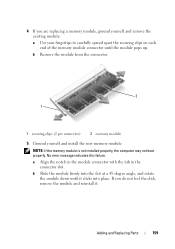
Adding and Replacing Parts 161 b Remove the module from the connector. 1 2 1 memory module cover 2 captive screw NOTICE: To prevent damage to the memory module connector, do not use tools to spread the memory-module securing clips. 3 If you are replacing a memory module, ground yourself and remove the existing module: a Use your fingertips to carefully spread apart the securing clips on each end of the memory module connector until the module pops up.
Adding and Replacing Parts 161 b Remove the module from the connector. 1 2 1 memory module cover 2 captive screw NOTICE: To prevent damage to the memory module connector, do not use tools to spread the memory-module securing clips. 3 If you are replacing a memory module, ground yourself and remove the existing module: a Use your fingertips to carefully spread apart the securing clips on each end of the memory module connector until the module pops up.

User's Guide
Page 162
2 1 1 securing clips (2 per connector) 2 memory module NOTICE: Insert memory modules at a 45-degree angle, and rotate the module down until it . 162 Adding and Replacing Parts a Align the notch in the module edge connector with the tab in the connector slot. If you do not feel the click, remove the module ...
2 1 1 securing clips (2 per connector) 2 memory module NOTICE: Insert memory modules at a 45-degree angle, and rotate the module down until it . 162 Adding and Replacing Parts a Align the notch in the module edge connector with the tab in the connector slot. If you do not feel the click, remove the module ...
User's Guide
Page 163
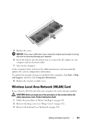
CAUTION: Before you ordered a WLAN card with your computer and an electrical outlet. 7 Turn on page 153). Adding and Replacing Parts 163 Forcing the cover to close may damage your computer. 6 Insert the battery into the battery bay, or connect the AC adapter to your computer, ... the safety instructions in the Product Information Guide. 1 Follow the procedures in the computer, click Start→ Help and Support, and then click Computer Information. 8 Replace the memory module cover. 5 Replace the cover. NOTICE: If the cover is already installed.
CAUTION: Before you ordered a WLAN card with your computer and an electrical outlet. 7 Turn on page 153). Adding and Replacing Parts 163 Forcing the cover to close may damage your computer. 6 Insert the battery into the battery bay, or connect the AC adapter to your computer, ... the safety instructions in the Product Information Guide. 1 Follow the procedures in the computer, click Start→ Help and Support, and then click Computer Information. 8 Replace the memory module cover. 5 Replace the cover. NOTICE: If the cover is already installed.
User's Guide
Page 164
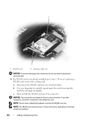
... the type of its connector. c Slide and lift the WLAN card out of card you ordered. 164 Adding and Replacing Parts If you are keyed to ensure correct insertion. NOTICE: The connectors are replacing a WLAN card, remove the existing card: a Disconnect the WLAN card from any attached cables. If you feel resistance, check...
... the type of its connector. c Slide and lift the WLAN card out of card you ordered. 164 Adding and Replacing Parts If you are keyed to ensure correct insertion. NOTICE: The connectors are replacing a WLAN card, remove the existing card: a Disconnect the WLAN card from any attached cables. If you feel resistance, check...
User's Guide
Page 165
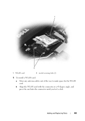
b Align the WLAN card with the connector at a 45-degree angle, and press the card into the connector until you feel a click. Adding and Replacing Parts 165 1 2 1 WLAN card 2 metal securing tabs (2) 5 To install a WLAN card: a Move any antenna cables out of the way to make space for the WLAN card.
b Align the WLAN card with the connector at a 45-degree angle, and press the card into the connector until you feel a click. Adding and Replacing Parts 165 1 2 1 WLAN card 2 metal securing tabs (2) 5 To install a WLAN card: a Move any antenna cables out of the way to make space for the WLAN card.
User's Guide
Page 166
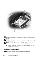
... to the WLAN card, ensuring that came with your WLAN card. NOTE: Your WLAN card may not be available in all regions. 166 Adding and Replacing Parts
... to the WLAN card, ensuring that came with your WLAN card. NOTE: Your WLAN card may not be available in all regions. 166 Adding and Replacing Parts


