User Guide
Page 193
...down the computer, disconnect the computer from the electrical outlet, and then let the battery and computer cool to verify that the computer turns on. Eliminate possible interference Turn off nearby fans, fluorescent lights, halogen lamps, or other appliances. Check the battery temperature If the battery temperature is ... battery may need to charge. Test the electrical outlet Ensure that the light is low or depleted. Troubleshooting: Dell Latitude D620 User's Guide NOTE: Battery operating time (the time the battery can hold a charge) decreases over time. Depending on /Kim%20&%20Jay...
...down the computer, disconnect the computer from the electrical outlet, and then let the battery and computer cool to verify that the computer turns on. Eliminate possible interference Turn off nearby fans, fluorescent lights, halogen lamps, or other appliances. Check the battery temperature If the battery temperature is ... battery may need to charge. Test the electrical outlet Ensure that the light is low or depleted. Troubleshooting: Dell Latitude D620 User's Guide NOTE: Battery operating time (the time the battery can hold a charge) decreases over time. Depending on /Kim%20&%20Jay...

Service Manual
Page 1
... data and tells you make better use of Microsoft Corporation; and is strictly forbidden. Dell™ Latitude™ D620 Service Manual Before You Begin System Components Media Bay Devices Hard Drive Hinge Cover Keyboard ...Memory Display Assembly Internal Card with Bluetooth® Wireless Technology Communications Cards Coin-Cell Battery Palm Rest Modem Processor Thermal-Cooling Assembly Processor Module Speaker Microphone PC Card Reader System Board Fan...
... data and tells you make better use of Microsoft Corporation; and is strictly forbidden. Dell™ Latitude™ D620 Service Manual Before You Begin System Components Media Bay Devices Hard Drive Hinge Cover Keyboard ...Memory Display Assembly Internal Card with Bluetooth® Wireless Technology Communications Cards Coin-Cell Battery Palm Rest Modem Processor Thermal-Cooling Assembly Processor Module Speaker Microphone PC Card Reader System Board Fan...
Service Manual
Page 2
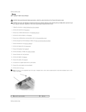
... Hard Drive). 3. Remove the palm rest (see Memory). 5. Remove the memory module(s) (see Palm Rest). 12. Disconnect the fan power cable from your body before you touch any of your computer, discharge static electricity from the system board. 15. Remove any ...(see Fan). Remove the fan (see Display Assembly). 11. You can do so by touching an unpainted metal surface. 1. Remove the keyboard (see Processor Thermal-Cooling Assembly). 7. Remove the processor thermal-cooling assembly (see Keyboard). 10. Back to Contents Page Base Dell™ Latitude™ D620 Service Manual...
... Hard Drive). 3. Remove the palm rest (see Memory). 5. Remove the memory module(s) (see Palm Rest). 12. Disconnect the fan power cable from your body before you touch any of your computer, discharge static electricity from the system board. 15. Remove any ...(see Fan). Remove the fan (see Display Assembly). 11. You can do so by touching an unpainted metal surface. 1. Remove the keyboard (see Processor Thermal-Cooling Assembly). 7. Remove the processor thermal-cooling assembly (see Keyboard). 10. Back to Contents Page Base Dell™ Latitude™ D620 Service Manual...
Service Manual
Page 16
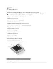
...x 5-mm screw that secures the fan to the base. 1 fan assembly 2 M2.5 x 5-mm screw 17. Follow the instructions in the Product Information Guide. Remove the processor (see Processor Thermal-Cooling Assembly). 7. Remove the processor thermal-cooling assembly (see Processor Module). 8....15. CAUTION: To prevent static damage to components inside your computer's electronic components. Back to Contents Page Fan Dell™ Latitude™ D620 Service Manual CAUTION: Before performing the following procedures, follow the safety instructions in Before Working Inside Your Computer...
...x 5-mm screw that secures the fan to the base. 1 fan assembly 2 M2.5 x 5-mm screw 17. Follow the instructions in the Product Information Guide. Remove the processor (see Processor Thermal-Cooling Assembly). 7. Remove the processor thermal-cooling assembly (see Processor Module). 8....15. CAUTION: To prevent static damage to components inside your computer's electronic components. Back to Contents Page Fan Dell™ Latitude™ D620 Service Manual CAUTION: Before performing the following procedures, follow the safety instructions in Before Working Inside Your Computer...
Service Manual
Page 36
... (see Memory). 8. Remove the memory module (see Display Assembly). 5. Remove the processor thermal-cooling assembly (see Hinge Cover). 3. The system board's BIOS chip contains the Service Tag, which ... PC Card Reader). 13. Remove the PC Card reader (see Speaker). 12. Disconnect the fan cable from the system board. 18. You can do so by touching an unpainted metal surface...Remove the modem (see Palm Rest). 10. Back to Contents Page System Board Dell™ Latitude™ D620 Service Manual Removing the System Board Installing the System Board Removing the System Board ...
... (see Memory). 8. Remove the memory module (see Display Assembly). 5. Remove the processor thermal-cooling assembly (see Hinge Cover). 3. The system board's BIOS chip contains the Service Tag, which ... PC Card Reader). 13. Remove the PC Card reader (see Speaker). 12. Disconnect the fan cable from the system board. 18. You can do so by touching an unpainted metal surface...Remove the modem (see Palm Rest). 10. Back to Contents Page System Board Dell™ Latitude™ D620 Service Manual Removing the System Board Installing the System Board Removing the System Board ...


