Service Manual
Page 9
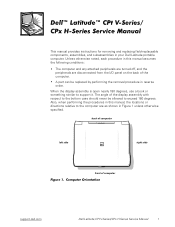
...use a book or something similar to the computer are disconnected from the I/O panel on the back of computer support.dell.com Dell Latitude CPt V-Series/CPx H-Series Service Manual 1 Also, when performing the procedures in this manual, the locations or directions relative to support it. ...of the display assembly with respect to the bottom case should never be replaced by performing the removal procedure in your Dell Latitude portable computer. This manual provides instructions for removing and replacing field-replaceable components, assemblies, and subassemblies in reverse order....
...use a book or something similar to the computer are disconnected from the I/O panel on the back of computer support.dell.com Dell Latitude CPt V-Series/CPx H-Series Service Manual 1 Also, when performing the procedures in this manual, the locations or directions relative to support it. ...of the display assembly with respect to the bottom case should never be replaced by performing the removal procedure in your Dell Latitude portable computer. This manual provides instructions for removing and replacing field-replaceable components, assemblies, and subassemblies in reverse order....
Service Manual
Page 10
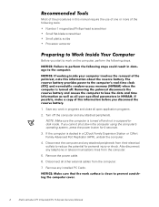
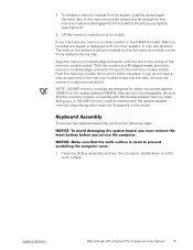
... in progress and close all other external cables from the computer. 7. If the computer is turned off the computer and any installed PC Cards. 2 Dell Latitude CPt V-Series/CPx H-Series Service Manual Remove any attached peripherals. Most of the procedures in this manual require the use of one or more of the following steps. 1. Turn...
... in progress and close all other external cables from the computer. 7. If the computer is turned off the computer and any installed PC Cards. 2 Dell Latitude CPt V-Series/CPx H-Series Service Manual Remove any attached peripherals. Most of the procedures in this manual require the use of one or more of the following steps. 1. Turn...
Service Manual
Page 11
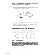
.... While you work, periodically touch the I /O panel on the back of the screw's label. M2.5x20 M2.5x10 M3.0x5 M2.5x4 M2.0x3 support.dell.com Dell Latitude CPt V-Series/CPx H-Series Service Manual 3 Slide the battery bay latch toward the right side of the battery bay (see Figure 2).
.... While you work, periodically touch the I /O panel on the back of the screw's label. M2.5x20 M2.5x10 M3.0x5 M2.5x4 M2.0x3 support.dell.com Dell Latitude CPt V-Series/CPx H-Series Service Manual 3 Slide the battery bay latch toward the right side of the battery bay (see Figure 2).

Service Manual
Page 12
...: M3 x 3 (3 each) Palmrest Assembly: M2.5 x 20 (5 each) System Board: M2.5 x 4 (2 each) Microprocessor Shield: 3 captive and 2 removable screws M2 x 3 (2 each) TCA and Exhaust Fan: M2.5 x 4 (2 each) 4 Dell Latitude CPt V-Series/CPx H-Series Service Manual
...: M3 x 3 (3 each) Palmrest Assembly: M2.5 x 20 (5 each) System Board: M2.5 x 4 (2 each) Microprocessor Shield: 3 captive and 2 removable screws M2 x 3 (2 each) TCA and Exhaust Fan: M2.5 x 4 (2 each) 4 Dell Latitude CPt V-Series/CPx H-Series Service Manual
Service Manual
Page 13
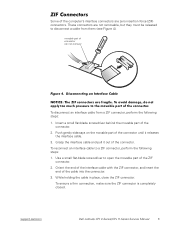
... disconnect an interface cable from them (see Figure 4). Use a small flat-blade screwdriver to disconnect a cable from a ZIF connector, perform the following steps: 1. support.dell.com Dell Latitude CPt V-Series/CPx H-Series Service Manual 5 Some of the connector. 2. Grasp the interface cable and pull it releases the interface cable. 3. Insert a small flat-blade screwdriver behind the...
... disconnect an interface cable from them (see Figure 4). Use a small flat-blade screwdriver to disconnect a cable from a ZIF connector, perform the following steps: 1. support.dell.com Dell Latitude CPt V-Series/CPx H-Series Service Manual 5 Some of the connector. 2. Grasp the interface cable and pull it releases the interface cable. 3. Insert a small flat-blade screwdriver behind the...
Service Manual
Page 14
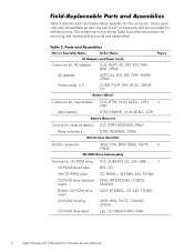
..., 24X, TSHBA PWA, INTERCONN, CD/DVD, OMAHA ASSY, BTM/BZL, CD, 24X, TSHBA ASSY, HSG, PLSTC, CD/DVD, OMHA LBL, CD, MEDIA BAY, TSHB 6 Dell Latitude CPt V-Series/CPx H-Series Service Manual Some parts may only be available as part of a service kit or assembly and are provided for removing and replacing these parts and...
..., 24X, TSHBA PWA, INTERCONN, CD/DVD, OMAHA ASSY, BTM/BZL, CD, 24X, TSHBA ASSY, HSG, PLSTC, CD/DVD, OMHA LBL, CD, MEDIA BAY, TSHB 6 Dell Latitude CPt V-Series/CPx H-Series Service Manual Some parts may only be available as part of a service kit or assembly and are provided for removing and replacing these parts and...
Service Manual
Page 15
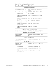
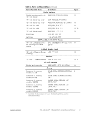
support.dell.com Dell Latitude CPt V-Series/CPx H-Series Service Manual 7 Diskette drive service kit SVC, SUBASSY, FD, F3, INT/EXT, 7 CRNA Diskette drive subassembly SUBASSY, FD, F3, INT/EXT, CRNA Diskette drive FD, ...
support.dell.com Dell Latitude CPt V-Series/CPx H-Series Service Manual 7 Diskette drive service kit SVC, SUBASSY, FD, F3, INT/EXT, 7 CRNA Diskette drive subassembly SUBASSY, FD, F3, INT/EXT, CRNA Diskette drive FD, ...
Service Manual
Page 16
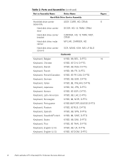
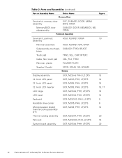
..., D-PTG Keyboard, Swiss KYBD, 88, SWI, D-PTG Keyboard, Thai KYBD, 87, THAI, D-PTG Keyboard, English (U.K.) KYBD, 88, UK, D-PTG Keyboard, English (U.S.) KYBD, 87, DOM, D-PTG 8 Dell Latitude CPt V-Series/CPx H-Series Service Manual
..., D-PTG Keyboard, Swiss KYBD, 88, SWI, D-PTG Keyboard, Thai KYBD, 87, THAI, D-PTG Keyboard, English (U.K.) KYBD, 88, UK, D-PTG Keyboard, English (U.S.) KYBD, 87, DOM, D-PTG 8 Dell Latitude CPt V-Series/CPx H-Series Service Manual
Service Manual
Page 17
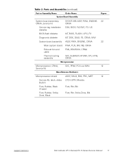
..., 256-MB 256MB, DIMM, SDRAM, LAT CRNA, FACT * Substitute the drive capacity for xxxxx, the drive height for yy, and the manufacturer for zzz. support.dell.com Dell Latitude CPt V-Series/CPx H-Series Service Manual 9
..., 256-MB 256MB, DIMM, SDRAM, LAT CRNA, FACT * Substitute the drive capacity for xxxxx, the drive height for yy, and the manufacturer for zzz. support.dell.com Dell Latitude CPt V-Series/CPx H-Series Service Manual 9
Service Manual
Page 18
..., ZPS SCR, M2.5X20, PHH, LP, ZPS SCR, M2.5X4, PHH, LP, ZPS 13 14 15 15, 17 13 14 9 6 12 23 19 22 10 Dell Latitude CPt V-Series/CPx H-Series Service Manual
..., ZPS SCR, M2.5X20, PHH, LP, ZPS SCR, M2.5X4, PHH, LP, ZPS 13 14 15 15, 17 13 14 9 6 12 23 19 22 10 Dell Latitude CPt V-Series/CPx H-Series Service Manual
Service Manual
Page 19
... Kit, latch, slider, LTCH, BTN, Module Button Foot, Rubber, Black (4 each) Foot, Rbr, Blk Foot, Rubber, Strike Zone, Black Foot, Rbr, Strike Zone, Blk support.dell.com Dell Latitude CPt V-Series/CPx H-Series Service Manual 11
... Kit, latch, slider, LTCH, BTN, Module Button Foot, Rubber, Black (4 each) Foot, Rbr, Blk Foot, Rubber, Strike Zone, Black Foot, Rbr, Strike Zone, Blk support.dell.com Dell Latitude CPt V-Series/CPx H-Series Service Manual 11

Service Manual
Page 20
display assembly keyboard palmrest assembly hard-disk drive system board main battery bottom case assembly modular bay device The following subsections provide instructions for removing and replacing field-replaceable parts and assemblies. 12 Dell Latitude CPt V-Series/CPx H-Series Service Manual
display assembly keyboard palmrest assembly hard-disk drive system board main battery bottom case assembly modular bay device The following subsections provide instructions for removing and replacing field-replaceable parts and assemblies. 12 Dell Latitude CPt V-Series/CPx H-Series Service Manual
Service Manual
Page 21
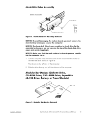
Turn the computer over, and remove the 5-mm screw from the center of computer 5-mm screw M3.0x5 hard-disk drive door 1. latch lock support.dell.com Dell Latitude CPt V-Series/CPx H-Series Service Manual 13 bottom of the hard-disk drive door (see Figure 6). Slide the drive door up and pull the drive out of the computer. 2. The drive is on the left side of the computer.
Turn the computer over, and remove the 5-mm screw from the center of computer 5-mm screw M3.0x5 hard-disk drive door 1. latch lock support.dell.com Dell Latitude CPt V-Series/CPx H-Series Service Manual 13 bottom of the hard-disk drive door (see Figure 6). Slide the drive door up and pull the drive out of the computer. 2. The drive is on the left side of the computer.

Service Manual
Page 22
... holding the latch open while pulling the device out of the modular bay with the other hand (see Figure 7). 1. Remove the memory module cover. 14 Dell Latitude CPt V-Series/CPx H-Series Service Manual
... holding the latch open while pulling the device out of the modular bay with the other hand (see Figure 7). 1. Remove the memory module cover. 14 Dell Latitude CPt V-Series/CPx H-Series Service Manual
Service Manual
Page 23
The slots on a flat work surface. Pivot the memory module down until it . support.dell.com Dell Latitude CPt V-Series/CPx H-Series Service Manual 15 Memory modules are notched so that the memory module is inserted with the double-stacked memory chips facing you only have one ...
The slots on a flat work surface. Pivot the memory module down until it . support.dell.com Dell Latitude CPt V-Series/CPx H-Series Service Manual 15 Memory modules are notched so that the memory module is inserted with the double-stacked memory chips facing you only have one ...

Service Manual
Page 24
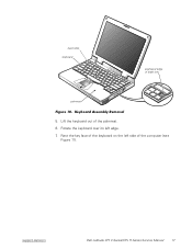
Turn the computer right-side up and open the display. 4. 10-mm screws (7) M2.5x10 2. Release the keyboard from the palmrest assembly by inserting a small flat-blade screwdriver under the edge of the keyboard. 16 Dell Latitude CPt V-Series/CPx H-Series Service Manual Remove the seven 10-mm screws, labeled with a "circle K," that secure the keyboard to the computer (see Figure 10), and lift the right edge of the blank key (see Figure 9). 3.
Turn the computer right-side up and open the display. 4. 10-mm screws (7) M2.5x10 2. Release the keyboard from the palmrest assembly by inserting a small flat-blade screwdriver under the edge of the keyboard. 16 Dell Latitude CPt V-Series/CPx H-Series Service Manual Remove the seven 10-mm screws, labeled with a "circle K," that secure the keyboard to the computer (see Figure 10), and lift the right edge of the blank key (see Figure 9). 3.
Service Manual
Page 25
Rotate the keyboard over its left side of the palmrest. 6. support.dell.com Dell Latitude CPt V-Series/CPx H-Series Service Manual 17 Lift the keyboard out of the computer (see Figure 11). Rest the key face of the keyboard on the left edge. 7. track stick keyboard scalloped edge of blank key palmrest 5.
Rotate the keyboard over its left side of the palmrest. 6. support.dell.com Dell Latitude CPt V-Series/CPx H-Series Service Manual 17 Lift the keyboard out of the computer (see Figure 11). Rest the key face of the keyboard on the left edge. 7. track stick keyboard scalloped edge of blank key palmrest 5.
Service Manual
Page 26
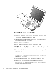
... circuit (FPC). 10. Ensure that the contact side of the computer with its key face down when you lower the keyboard into the palmrest. 18 Dell Latitude CPt V-Series/CPx H-Series Service Manual track stick cable keyboard cable 8. Remove the keyboard assembly. Place the keyboard on the system board. Carefully turn the keyboard over and...
... circuit (FPC). 10. Ensure that the contact side of the computer with its key face down when you lower the keyboard into the palmrest. 18 Dell Latitude CPt V-Series/CPx H-Series Service Manual track stick cable keyboard cable 8. Remove the keyboard assembly. Place the keyboard on the system board. Carefully turn the keyboard over and...
Service Manual
Page 27
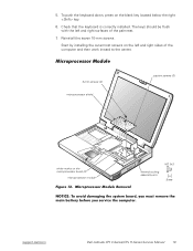
... the keyboard is correctly installed. 5. To push the keyboard down, press on the microprocessor board (2) microprocessor module M2.0x3 thermal cooling assembly arm support.dell.com Dell Latitude CPt V-Series/CPx H-Series Service Manual 19 The keys should be flush with the left and right sides of the palmrest. 7. Reinstall the seven 10-mm screws. Start...
... the keyboard is correctly installed. 5. To push the keyboard down, press on the microprocessor board (2) microprocessor module M2.0x3 thermal cooling assembly arm support.dell.com Dell Latitude CPt V-Series/CPx H-Series Service Manual 19 The keys should be flush with the left and right sides of the palmrest. 7. Reinstall the seven 10-mm screws. Start...

Service Manual
Page 28
Rotate the arm of the shield to secure the microprocessor module and shield. 20 Dell Latitude CPt V-Series/CPx H-Series Service Manual When you reinstall the microprocessor module in the system board, make sure that is directly over this corner to the microprocessor module (see ...
Rotate the arm of the shield to secure the microprocessor module and shield. 20 Dell Latitude CPt V-Series/CPx H-Series Service Manual When you reinstall the microprocessor module in the system board, make sure that is directly over this corner to the microprocessor module (see ...


