
Service Manual
Page 5
... 2 Screw Identification and Tightening 3 ZIF Connectors 5 Field-Replaceable Parts and Assemblies 6 Removing Field-Replaceable Parts and Assemblies 12 Hard-Disk Drive Assembly 13 Modular Bay Devices (Diskette Drive, CD-ROM Drive, DVD-ROM Drive, SuperDisk LS-120 Drive, Battery, or Travel Module 13 Memory Module Cover 14 Memory Modules 14 Keyboard Assembly 15 Microprocessor Module 19...
... 2 Screw Identification and Tightening 3 ZIF Connectors 5 Field-Replaceable Parts and Assemblies 6 Removing Field-Replaceable Parts and Assemblies 12 Hard-Disk Drive Assembly 13 Modular Bay Devices (Diskette Drive, CD-ROM Drive, DVD-ROM Drive, SuperDisk LS-120 Drive, Battery, or Travel Module 13 Memory Module Cover 14 Memory Modules 14 Keyboard Assembly 15 Microprocessor Module 19...

Service Manual
Page 6
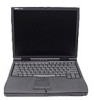
... 2. Figure 5. Figure 22. Figure 23. Figure 9. Figure 15. Computer Orientation 1 Main Battery Assembly Removal 3 Screw Identification 3 Disconnecting an Interface Cable 5 Exploded View-Computer 12 Hard-Disk Drive Assembly Removal 13 Modular Bay Device Removal 13 Memory Module Removal 14 Removing the Keyboard Assembly Screws 16 Keyboard Assembly Removal 17 Keyboard and Track...
... 2. Figure 5. Figure 22. Figure 23. Figure 9. Figure 15. Computer Orientation 1 Main Battery Assembly Removal 3 Screw Identification 3 Disconnecting an Interface Cable 5 Exploded View-Computer 12 Hard-Disk Drive Assembly Removal 13 Modular Bay Device Removal 13 Memory Module Removal 14 Removing the Keyboard Assembly Screws 16 Keyboard Assembly Removal 17 Keyboard and Track...

Service Manual
Page 12
... Assembly: M2.5 x 20 (5 each) System Board: M2.5 x 4 (2 each) Microprocessor Shield: 3 captive and 2 removable screws M2 x 3 (2 each) TCA and Exhaust Fan: M2.5 x 4 (2 each) 4 Dell Latitude CPt V-Series/CPx H-Series Service Manual Hard-Disk Drive: M3 x 5 (1 each) Keyboard Assembly: M2.5 x 10 (7 each) Display Assembly: M2.5 x 4 (3 each) Display Assembly Bezel: Rubber Screw Covers (4 each) Plastic Screw Covers (2 each...
... Assembly: M2.5 x 20 (5 each) System Board: M2.5 x 4 (2 each) Microprocessor Shield: 3 captive and 2 removable screws M2 x 3 (2 each) TCA and Exhaust Fan: M2.5 x 4 (2 each) 4 Dell Latitude CPt V-Series/CPx H-Series Service Manual Hard-Disk Drive: M3 x 5 (1 each) Keyboard Assembly: M2.5 x 10 (7 each) Display Assembly: M2.5 x 4 (3 each) Display Assembly Bezel: Rubber Screw Covers (4 each) Plastic Screw Covers (2 each...
Service Manual
Page 15
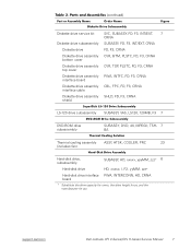
...dell.com Dell Latitude CPt V-Series/CPx H-Series Service Manual 7 Diskette drive service kit SVC, SUBASSY, FD, F3, INT/EXT, 7 CRNA Diskette drive subassembly SUBASSY, FD, F3, INT/EXT, CRNA Diskette drive FD, F3, CRNA Diskette drive assembly CVR, BTM, PLSTC, FD, F3, CRNA bottom cover Diskette drive assembly CVR, TOP, PLSTC, FD, F3, CRNA top cover Diskette drive... Hard-disk drive, subassembly SUBASSY, HD, xxxxx, yyyMM, zzz* 6 Hard-disk drive HD, xxxxx, I, F2, yyMM, zzz* Hard-disk drive interface PWA, INTERCONN, HD, CRNA board * Substitute the drive capacity for xxxxx, the drive ...
...dell.com Dell Latitude CPt V-Series/CPx H-Series Service Manual 7 Diskette drive service kit SVC, SUBASSY, FD, F3, INT/EXT, 7 CRNA Diskette drive subassembly SUBASSY, FD, F3, INT/EXT, CRNA Diskette drive FD, F3, CRNA Diskette drive assembly CVR, BTM, PLSTC, FD, F3, CRNA bottom cover Diskette drive assembly CVR, TOP, PLSTC, FD, F3, CRNA top cover Diskette drive... Hard-disk drive, subassembly SUBASSY, HD, xxxxx, yyyMM, zzz* 6 Hard-disk drive HD, xxxxx, I, F2, yyMM, zzz* Hard-disk drive interface PWA, INTERCONN, HD, CRNA board * Substitute the drive capacity for xxxxx, the drive ...
Service Manual
Page 16
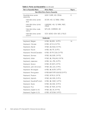
... ASSY, CARR, HD, CRNA 6 assembly Hard-disk drive carrier door DOOR, HD, 12.7MM, CRNA Hard-disk drive carrier bracket CARRIER, HD, 12.7MM, MET, CRNA Hard-disk drive mylar carrier MYLAR, CARRIER, HD Hard-disk drive carrier screws SCR, M3X3, KSH, MS, LP, BLO Keyboard, Belgian KYBD, 88, BEL, D-PTG 10 Keyboard, Chinese KYBD, 87, CHI, D-PTG..., D-PTG Keyboard, Swiss KYBD, 88, SWI, D-PTG Keyboard, Thai KYBD, 87, THAI, D-PTG Keyboard, English (U.K.) KYBD, 88, UK, D-PTG Keyboard, English (U.S.) KYBD, 87, DOM, D-PTG 8 Dell Latitude CPt V-Series/CPx H-Series Service Manual
... ASSY, CARR, HD, CRNA 6 assembly Hard-disk drive carrier door DOOR, HD, 12.7MM, CRNA Hard-disk drive carrier bracket CARRIER, HD, 12.7MM, MET, CRNA Hard-disk drive mylar carrier MYLAR, CARRIER, HD Hard-disk drive carrier screws SCR, M3X3, KSH, MS, LP, BLO Keyboard, Belgian KYBD, 88, BEL, D-PTG 10 Keyboard, Chinese KYBD, 87, CHI, D-PTG..., D-PTG Keyboard, Swiss KYBD, 88, SWI, D-PTG Keyboard, Thai KYBD, 87, THAI, D-PTG Keyboard, English (U.K.) KYBD, 88, UK, D-PTG Keyboard, English (U.S.) KYBD, 87, DOM, D-PTG 8 Dell Latitude CPt V-Series/CPx H-Series Service Manual
Service Manual
Page 18
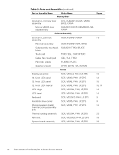
... Speaker (2 each) SPKR, 20X40, 1W, 8OHMS Display assembly 14.1-inch LCD panel 12.1-inch LCD panel 12.1-inch LCD inverter LCD hinge LCD bezel Keyboard Hard-disk drive carrier Microprocessor shield/ thermal cooling assembly arm Thermal cooling assembly Palmrest System board assembly SCR, M2.5x4, PHH, LP, ZPS SCR, M2X3, PHH, LP..., ZPS SCR, M2.5X20, PHH, LP, ZPS SCR, M2.5X4, PHH, LP, ZPS 13 14 15 15, 17 13 14 9 6 12 23 19 22 10 Dell Latitude CPt V-Series/CPx H-Series Service Manual
... Speaker (2 each) SPKR, 20X40, 1W, 8OHMS Display assembly 14.1-inch LCD panel 12.1-inch LCD panel 12.1-inch LCD inverter LCD hinge LCD bezel Keyboard Hard-disk drive carrier Microprocessor shield/ thermal cooling assembly arm Thermal cooling assembly Palmrest System board assembly SCR, M2.5x4, PHH, LP, ZPS SCR, M2X3, PHH, LP..., ZPS SCR, M2.5X20, PHH, LP, ZPS SCR, M2.5X4, PHH, LP, ZPS 13 14 15 15, 17 13 14 9 6 12 23 19 22 10 Dell Latitude CPt V-Series/CPx H-Series Service Manual

Service Manual
Page 20
display assembly keyboard palmrest assembly hard-disk drive system board main battery bottom case assembly modular bay device The following subsections provide instructions for removing and replacing field-replaceable parts and assemblies. 12 Dell Latitude CPt V-Series/CPx H-Series Service Manual
display assembly keyboard palmrest assembly hard-disk drive system board main battery bottom case assembly modular bay device The following subsections provide instructions for removing and replacing field-replaceable parts and assemblies. 12 Dell Latitude CPt V-Series/CPx H-Series Service Manual
Service Manual
Page 21
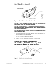
latch lock support.dell.com Dell Latitude CPt V-Series/CPx H-Series Service Manual 13 The drive is on the left side of the hard-disk drive door (see Figure 6). Turn the computer over, and remove the 5-mm screw from the center of the computer. 2. Slide the drive door up and pull the drive out of computer 5-mm screw M3.0x5 hard-disk drive door 1. bottom of the computer.
latch lock support.dell.com Dell Latitude CPt V-Series/CPx H-Series Service Manual 13 The drive is on the left side of the hard-disk drive door (see Figure 6). Turn the computer over, and remove the 5-mm screw from the center of the computer. 2. Slide the drive door up and pull the drive out of computer 5-mm screw M3.0x5 hard-disk drive door 1. bottom of the computer.

Service Manual
Page 42
Remove the display assembly. 5. Verify that outline the captive washers. 34 Dell Latitude CPt V-Series/CPx H-Series Service Manual diskette that provides a utility for the white circles on the system board that the PC Card ejectors do not extend ... system board assembly. 1. The 4-mm screw with captive washer located on the far right side of the computer in front of the computer between the hard-disk drive assembly and the PC Card slot. Remove the main battery. 2. Remove the following two screws from the PC Card slot. 8.
Remove the display assembly. 5. Verify that outline the captive washers. 34 Dell Latitude CPt V-Series/CPx H-Series Service Manual diskette that provides a utility for the white circles on the system board that the PC Card ejectors do not extend ... system board assembly. 1. The 4-mm screw with captive washer located on the far right side of the computer in front of the computer between the hard-disk drive assembly and the PC Card slot. Remove the main battery. 2. Remove the following two screws from the PC Card slot. 8.

Service Manual
Page 46
hard-disk drive assembly removal, 13 palmrest assembly removal, 29 inverter, 12.1-inch LCD panel removal, 26 replacement, 27 keyboard assembly removal, 16 memory module removal, 14 memory ... modular bay devices removal, 13 module latch assemblies removal, 32 reserve battery removal, 31 screw identification and tightening, 3 sockets memory module, 14 SuperDisk LS-120 drive removal, 13 system board assembly removal, 19 thermal cooling assembly removal, 36 tools, 2 travel module removal, 13 ZIF connectors, 5 2 Dell Latitude CPt V-Series/CPx H-Series Service Manual
hard-disk drive assembly removal, 13 palmrest assembly removal, 29 inverter, 12.1-inch LCD panel removal, 26 replacement, 27 keyboard assembly removal, 16 memory module removal, 14 memory ... modular bay devices removal, 13 module latch assemblies removal, 32 reserve battery removal, 31 screw identification and tightening, 3 sockets memory module, 14 SuperDisk LS-120 drive removal, 13 system board assembly removal, 19 thermal cooling assembly removal, 36 tools, 2 travel module removal, 13 ZIF connectors, 5 2 Dell Latitude CPt V-Series/CPx H-Series Service Manual


