
Service Manual
Page 5
... Drive Assembly 13 Modular Bay Devices (Diskette Drive, CD-ROM Drive, DVD-ROM Drive, SuperDisk LS-120 Drive, Battery, or Travel Module 13 Memory Module Cover 14 Memory Modules 14 Keyboard Assembly 15 Microprocessor Module 19 Replacing the Microprocessor Module 20 Display Assembly 21 Display Assembly Bezel 22 14.1-Inch Display LCD...
... Drive Assembly 13 Modular Bay Devices (Diskette Drive, CD-ROM Drive, DVD-ROM Drive, SuperDisk LS-120 Drive, Battery, or Travel Module 13 Memory Module Cover 14 Memory Modules 14 Keyboard Assembly 15 Microprocessor Module 19 Replacing the Microprocessor Module 20 Display Assembly 21 Display Assembly Bezel 22 14.1-Inch Display LCD...

Service Manual
Page 6
... 1 Main Battery Assembly Removal 3 Screw Identification 3 Disconnecting an Interface Cable 5 Exploded View-Computer 12 Hard-Disk Drive Assembly Removal 13 Modular Bay Device Removal 13 Memory Module Removal 14 Removing the Keyboard Assembly Screws 16 Keyboard Assembly Removal 17 Keyboard and Track Stick Cables 18 Microprocessor Module Removal 19 Display Assembly...
... 1 Main Battery Assembly Removal 3 Screw Identification 3 Disconnecting an Interface Cable 5 Exploded View-Computer 12 Hard-Disk Drive Assembly Removal 13 Modular Bay Device Removal 13 Memory Module Removal 14 Removing the Keyboard Assembly Screws 16 Keyboard Assembly Removal 17 Keyboard and Track Stick Cables 18 Microprocessor Module Removal 19 Display Assembly...
Service Manual
Page 17
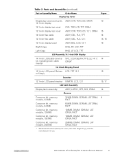
support.dell.com Dell Latitude CPt V-Series/CPx H-Series Service Manual 9 Display top-cover service kit, 14.1-inch display 14.1-inch display top cover 12.1-inch display top cover 14.1-inch ..., LCD, 12.1 14 15 15, 17 Display latch assembly ASSY, LATCH, SPR, DIS, CRNA 14 Customer kit, memory module, 32-MB 32MB, DIMM, SDRAM, LAT CRNA, 8 FACT Customer kit, memory module, 64-MB 64MB, DIMM, SDRAM, LAT CRNA, FACT Customer kit, memory module, 128-MB 128MB, DIMM, SDRAM, LAT CRNA, FACT Customer kit...
support.dell.com Dell Latitude CPt V-Series/CPx H-Series Service Manual 9 Display top-cover service kit, 14.1-inch display 14.1-inch display top cover 12.1-inch display top cover 14.1-inch ..., LCD, 12.1 14 15 15, 17 Display latch assembly ASSY, LATCH, SPR, DIS, CRNA 14 Customer kit, memory module, 32-MB 32MB, DIMM, SDRAM, LAT CRNA, 8 FACT Customer kit, memory module, 64-MB 64MB, DIMM, SDRAM, LAT CRNA, FACT Customer kit, memory module, 128-MB 128MB, DIMM, SDRAM, LAT CRNA, FACT Customer kit...
Service Manual
Page 18
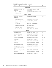
Service kit, memory door assembly Memory/BIOS door subassembly SVC, SUBASSY, DOOR, MEM/ BIOS, CRNA SUBASSY, DOOR, MEM/BIOS, NB, CRNA Service kit, palmrest ASSY, PLMRST, CRNA 19 assembly Palmrest assembly ..., ZPS SCR, M2.5X20, PHH, LP, ZPS SCR, M2.5X4, PHH, LP, ZPS 13 14 15 15, 17 13 14 9 6 12 23 19 22 10 Dell Latitude CPt V-Series/CPx H-Series Service Manual
Service kit, memory door assembly Memory/BIOS door subassembly SVC, SUBASSY, DOOR, MEM/ BIOS, CRNA SUBASSY, DOOR, MEM/BIOS, NB, CRNA Service kit, palmrest ASSY, PLMRST, CRNA 19 assembly Palmrest assembly ..., ZPS SCR, M2.5X20, PHH, LP, ZPS SCR, M2.5X4, PHH, LP, ZPS 13 14 15 15, 17 13 14 9 6 12 23 19 22 10 Dell Latitude CPt V-Series/CPx H-Series Service Manual

Service Manual
Page 22
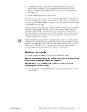
... the other hand (see Figure 7). 1. Insert a flat-bladed screwdriver under the indentation in the bottom case assembly and lift the cover. Remove the memory module cover. 14 Dell Latitude CPt V-Series/CPx H-Series Service Manual Close the display and turn the computer upside down on a flat work surface. 2. Push the module latch toward the...
... the other hand (see Figure 7). 1. Insert a flat-bladed screwdriver under the indentation in the bottom case assembly and lift the cover. Remove the memory module cover. 14 Dell Latitude CPt V-Series/CPx H-Series Service Manual Close the display and turn the computer upside down on a flat work surface. 2. Push the module latch toward the...
Service Manual
Page 23
...firmly into place. NOTE: 192-MB memory modules are notched so that the memory module is inserted with the double-stacked memory chips facing you only have one memory module, install it should pop up slightly) (see Figure 8). 3. Pivot the memory module down until it . If you.... The slots on a flat work surface. Be sure that the memory module can be firmly seated only one direction. To release a memory module from its socket. To remove the keyboard assembly, perform the following steps. 1. support.dell.com Dell Latitude CPt V-Series/CPx H-Series Service Manual 15 2.
...firmly into place. NOTE: 192-MB memory modules are notched so that the memory module is inserted with the double-stacked memory chips facing you only have one memory module, install it should pop up slightly) (see Figure 8). 3. Pivot the memory module down until it . If you.... The slots on a flat work surface. Be sure that the memory module can be firmly seated only one direction. To release a memory module from its socket. To remove the keyboard assembly, perform the following steps. 1. support.dell.com Dell Latitude CPt V-Series/CPx H-Series Service Manual 15 2.

Service Manual
Page 43
Follow the instructions on the computer. support.dell.com Dell Latitude CPt V-Series/CPx H-Series Service Manual 35 Be sure to transfer the memory module(s) to enter the system's service tag number into the diskette drive, and turn on the display screen. 4-mm screws with captive washers (2) system board ...
Follow the instructions on the computer. support.dell.com Dell Latitude CPt V-Series/CPx H-Series Service Manual 35 Be sure to transfer the memory module(s) to enter the system's service tag number into the diskette drive, and turn on the display screen. 4-mm screws with captive washers (2) system board ...

Service Manual
Page 46
...13 palmrest assembly removal, 29 inverter, 12.1-inch LCD panel removal, 26 replacement, 27 keyboard assembly removal, 16 memory module removal, 14 memory module cover removal, 14 microprocessor module removal, 19 modular bay devices removal, 13 module latch assemblies removal, 32 ...reserve battery removal, 31 screw identification and tightening, 3 sockets memory module, 14 SuperDisk LS-120 drive removal, 13 system board assembly removal, 19 thermal cooling assembly removal, 36 tools, 2 travel module removal, 13 ZIF connectors, 5 2 Dell Latitude CPt V-Series/CPx H-Series Service Manual
...13 palmrest assembly removal, 29 inverter, 12.1-inch LCD panel removal, 26 replacement, 27 keyboard assembly removal, 16 memory module removal, 14 memory module cover removal, 14 microprocessor module removal, 19 modular bay devices removal, 13 module latch assemblies removal, 32 ...reserve battery removal, 31 screw identification and tightening, 3 sockets memory module, 14 SuperDisk LS-120 drive removal, 13 system board assembly removal, 19 thermal cooling assembly removal, 36 tools, 2 travel module removal, 13 ZIF connectors, 5 2 Dell Latitude CPt V-Series/CPx H-Series Service Manual


