
Service Manual
Page 5
...-ROM Drive, DVD-ROM Drive, CD-RW Drive, SuperDisk LS-120 Drive, Battery, or Travel Module) . . . . 12 Memory Module Cover 12 Removing the Memory Module Cover 12 Memory Modules 13 Removing the Memory Modules 13 Replacing the Memory Modules 13 Keyboard Assembly 14 Removing the Keyboard Assembly 14 Replacing the Keyboard Assembly 16 Microprocessor Module...
...-ROM Drive, DVD-ROM Drive, CD-RW Drive, SuperDisk LS-120 Drive, Battery, or Travel Module) . . . . 12 Memory Module Cover 12 Removing the Memory Module Cover 12 Memory Modules 13 Removing the Memory Modules 13 Replacing the Memory Modules 13 Keyboard Assembly 14 Removing the Keyboard Assembly 14 Replacing the Keyboard Assembly 16 Microprocessor Module...
Service Manual
Page 6
... Battery Removal 3 Screw Identification 3 Disconnecting a Cable from an Interface Connector 5 Exploded View-Computer 10 Hard-Disk Drive Assembly Removal 11 Modular Bay Device Removal 12 Memory Module Removal 13 Removing the Keyboard Assembly Screws 14 Keyboard Assembly Removal 15 Keyboard and Track Stick Cables and Connectors 16 Microprocessor Module Removal 18...
... Battery Removal 3 Screw Identification 3 Disconnecting a Cable from an Interface Connector 5 Exploded View-Computer 10 Hard-Disk Drive Assembly Removal 11 Modular Bay Device Removal 12 Memory Module Removal 13 Removing the Keyboard Assembly Screws 14 Keyboard Assembly Removal 15 Keyboard and Track Stick Cables and Connectors 16 Microprocessor Module Removal 18...

Service Manual
Page 16
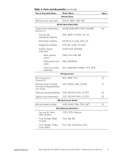
..., CH-ST Customer kit, memory CUS, 32MB, DIMM, SDRAM 8 module, 32-MB Customer kit, memory module, 64-MB CUS, 64MB, DIMM, SDRAM Customer kit, memory module, 128-MB CUS, 128MB, DIMM, SDRAM Customer kit, memory module, 192-MB CUS, 192MB, DIMM, SDRAM Customer kit, memory module, 256-MB CUS, 256MB, DIMM, SDRAM 8 Dell Latitude CPt V/CPt S Series and CPx...
..., CH-ST Customer kit, memory CUS, 32MB, DIMM, SDRAM 8 module, 32-MB Customer kit, memory module, 64-MB CUS, 64MB, DIMM, SDRAM Customer kit, memory module, 128-MB CUS, 128MB, DIMM, SDRAM Customer kit, memory module, 192-MB CUS, 192MB, DIMM, SDRAM Customer kit, memory module, 256-MB CUS, 256MB, DIMM, SDRAM 8 Dell Latitude CPt V/CPt S Series and CPx...
Service Manual
Page 17
Memory door assembly DOOR, MEM, MET, NB System board assembly, SVCKIT, MB ASSY, PWA, ENGINE 22 service kit Service tag installation diskette DSK, BIOS, FLDSVC, F3, ... Kit, latch, slider, Button Foot, Rubber, Black (4 each) Foot, Rubber, Strike Zone, Black LTCH, BTN, Module Foot, Rbr, Blk Foot, Rbr, Strike Zone, Blk support.dell.com Dell Latitude CPt V/CPt S Series and CPx H/CPx J Series Service Manual 9
Memory door assembly DOOR, MEM, MET, NB System board assembly, SVCKIT, MB ASSY, PWA, ENGINE 22 service kit Service tag installation diskette DSK, BIOS, FLDSVC, F3, ... Kit, latch, slider, Button Foot, Rubber, Black (4 each) Foot, Rubber, Strike Zone, Black LTCH, BTN, Module Foot, Rbr, Blk Foot, Rbr, Strike Zone, Blk support.dell.com Dell Latitude CPt V/CPt S Series and CPx H/CPx J Series Service Manual 9
Service Manual
Page 20
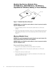
.... 2. Release the memory module cover. Push the module latch toward the unlock icon. Keep holding the latch open while pulling the device out of the modular bay with the other hand (see Figure 7). 1. Insert a flat-blade screwdriver under the indentation in the bottom case assembly and lift the cover. 12 Dell Latitude CPt V/CPt S Series...
.... 2. Release the memory module cover. Push the module latch toward the unlock icon. Keep holding the latch open while pulling the device out of the modular bay with the other hand (see Figure 7). 1. Insert a flat-blade screwdriver under the indentation in the bottom case assembly and lift the cover. 12 Dell Latitude CPt V/CPt S Series...
Service Manual
Page 21
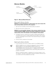
..., in the DIMM A socket. Memory modules are notched so that the memory module is inserted with the double-stacked memory chips facing down does not fit properly in the socket. The module should pop up slightly (see Figure 8). 4. support.dell.com Dell Latitude CPt V/CPt S Series and CPx H/CPx J... Series Service Manual 13 To release a memory module from its socket, carefully spread apart the inner tabs of its socket. 1. Remove the main ...
..., in the DIMM A socket. Memory modules are notched so that the memory module is inserted with the double-stacked memory chips facing down does not fit properly in the socket. The module should pop up slightly (see Figure 8). 4. support.dell.com Dell Latitude CPt V/CPt S Series and CPx H/CPx J... Series Service Manual 13 To release a memory module from its socket, carefully spread apart the inner tabs of its socket. 1. Remove the main ...
Service Manual
Page 22
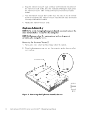
... work surface. 10-mm screws (7) M2.5x10 14 Dell Latitude CPt V/CPt S Series and CPx H/CPx J Series Service Manual Align the memory module's edge connector with the slot in the center of the memory module snaps into the tabs, remove the memory module and reinstall it clicks into the memory module socket. 3. With the module at a 45-degree...
... work surface. 10-mm screws (7) M2.5x10 14 Dell Latitude CPt V/CPt S Series and CPx H/CPx J Series Service Manual Align the memory module's edge connector with the slot in the center of the memory module snaps into the tabs, remove the memory module and reinstall it clicks into the memory module socket. 3. With the module at a 45-degree...
Service Manual
Page 43
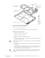
...to the replacement system board assembly. 5. Replace the microprocessor, the palmrest assembly, the display assembly and the keyboard assembly. NOTE: Be sure to transfer the memory module(s) to enter the system's service tag number into the appropriate drive, and turn on the computer. Remove the modem (if present). 11. Lift ...diskette (or CD-ROM) that accompanied the replacement system board assembly into the BIOS of the bottom case assembly. 1. Install the replacement system board. 2. support.dell.com Dell Latitude CPt V/CPt S Series and CPx H/CPx J Series Service Manual 35
...to the replacement system board assembly. 5. Replace the microprocessor, the palmrest assembly, the display assembly and the keyboard assembly. NOTE: Be sure to transfer the memory module(s) to enter the system's service tag number into the appropriate drive, and turn on the computer. Remove the modem (if present). 11. Lift ...diskette (or CD-ROM) that accompanied the replacement system board assembly into the BIOS of the bottom case assembly. 1. Install the replacement system board. 2. support.dell.com Dell Latitude CPt V/CPt S Series and CPx H/CPx J Series Service Manual 35
Service Manual
Page 48
... bay devices removal, 12 module latch assemblies removal, 37 screw identification and tightening, 3 sockets memory module, 13 SuperDisk LS-120 drive removal, 12 system board assembly removal, 18 thermal cooling assembly removal, 36 tools, 2 travel module removal, 12 ZIF connectors, 5 palmrest assembly removal, 30 2 Dell Latitude CPt V/CPt S Series and CPx H/Cpx J Series Service Manual
... bay devices removal, 12 module latch assemblies removal, 37 screw identification and tightening, 3 sockets memory module, 13 SuperDisk LS-120 drive removal, 12 system board assembly removal, 18 thermal cooling assembly removal, 36 tools, 2 travel module removal, 12 ZIF connectors, 5 palmrest assembly removal, 30 2 Dell Latitude CPt V/CPt S Series and CPx H/Cpx J Series Service Manual
System Information Guide (multilanguage: English, Japanese, Chinese-Traditional, Chinese-Simplified, Korean, Thai)
Page 12
... in a nonconducting material, such as dirt, dust, food, liquids, temperature extremes, and overexposure to the cloth; Preliminary 1/25/00 1-8 Dell Latitude System Information Also, before you clean your computer, battery, and hard-disk drive from the top of commercial window cleaner. Apply the cleaner ...display to the system board. • Before you connect a cable make sure both connectors are asked to evaporate before removing the memory module or disconnecting the device to help avoid possible damage to the bottom. Hold a component such as baggage. then stroke the ...
... in a nonconducting material, such as dirt, dust, food, liquids, temperature extremes, and overexposure to the cloth; Preliminary 1/25/00 1-8 Dell Latitude System Information Also, before you clean your computer, battery, and hard-disk drive from the top of commercial window cleaner. Apply the cleaner ...display to the system board. • Before you connect a cable make sure both connectors are asked to evaporate before removing the memory module or disconnecting the device to help avoid possible damage to the bottom. Hold a component such as baggage. then stroke the ...
System Information Guide (multilanguage: English, Japanese, Chinese-Traditional, Chinese-Simplified, Korean, Thai)
Page 14
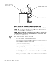
... 1/25/00 1-10 Dell Latitude System Information While you remove or install memory modules, observe the following safety guidelines: NOTE: For full instructions, see your User's Guide. • Turn off your computer and any attached peripherals. • Disconnect...metal surface of an input/output (I /O panel to dissipate any static electricity that might harm internal components. (Rev. 11/3/98) FILE LOCATION: \\Pd-xuzhan\d\FrameMaker\Dell\sndmm003\en\999CCA00en.fm computer positioned directly in front of user wrists relaxed and flat arms at desk level As you work, periodically touch the...
... 1/25/00 1-10 Dell Latitude System Information While you remove or install memory modules, observe the following safety guidelines: NOTE: For full instructions, see your User's Guide. • Turn off your computer and any attached peripherals. • Disconnect...metal surface of an input/output (I /O panel to dissipate any static electricity that might harm internal components. (Rev. 11/3/98) FILE LOCATION: \\Pd-xuzhan\d\FrameMaker\Dell\sndmm003\en\999CCA00en.fm computer positioned directly in front of user wrists relaxed and flat arms at desk level As you work, periodically touch the...

System Information Guide (multilanguage: English, Japanese, Chinese-Traditional, Chinese-Simplified, Korean, Thai)
Page 15
...undock it in the System Setup program). Preliminary 1/25/00 Dell Latitude System Information 1-11 Just before you of these precautions: To...the component. (Rev. 11/3/98) FILE LOCATION: \\Pd-xuzhan\d\FrameMaker\Dell\sndmm003\en\999CCA00en.fm Static electricity can harm electronic components inside the computer... NOTE: For full instructions, see the User's Guide. 1. support.dell.com DELL CONFIDENTIAL - You can do not remove the component from the antistatic ... body may appear throughout your Dell documentation to step 5. 4. To prevent static damage, discharge static electricity from...
...undock it in the System Setup program). Preliminary 1/25/00 Dell Latitude System Information 1-11 Just before you of these precautions: To...the component. (Rev. 11/3/98) FILE LOCATION: \\Pd-xuzhan\d\FrameMaker\Dell\sndmm003\en\999CCA00en.fm Static electricity can harm electronic components inside the computer... NOTE: For full instructions, see the User's Guide. 1. support.dell.com DELL CONFIDENTIAL - You can do not remove the component from the antistatic ... body may appear throughout your Dell documentation to step 5. 4. To prevent static damage, discharge static electricity from...


