
Service Manual
Page 5
... Before Working Inside Your Computer 2 Screw Identification 3 Disconnecting Interface Connectors 5 Removing a Cable from a ZIF Interface Connector 5 Replacing a Cable into a ZIF Interface Connector 5 Field-Replaceable Parts and Assemblies 6 Removing and Replacing Field-Replaceable Parts and Assemblies 10 Hard-Disk Drive Assembly 11 Removing the Hard-Disk Drive Assembly 11 Replacing the Hard-Disk Drive Assembly 11 Modular Bay Devices (Diskette Drive, CD-ROM Drive, DVD-ROM Drive, CD-RW Drive, SuperDisk LS-120 Drive, Battery, or Travel Module) . . . . 12 Memory Module Cover 12 Removing...
... Before Working Inside Your Computer 2 Screw Identification 3 Disconnecting Interface Connectors 5 Removing a Cable from a ZIF Interface Connector 5 Replacing a Cable into a ZIF Interface Connector 5 Field-Replaceable Parts and Assemblies 6 Removing and Replacing Field-Replaceable Parts and Assemblies 10 Hard-Disk Drive Assembly 11 Removing the Hard-Disk Drive Assembly 11 Replacing the Hard-Disk Drive Assembly 11 Modular Bay Devices (Diskette Drive, CD-ROM Drive, DVD-ROM Drive, CD-RW Drive, SuperDisk LS-120 Drive, Battery, or Travel Module) . . . . 12 Memory Module Cover 12 Removing...
Service Manual
Page 6
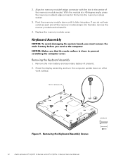
... Removing the System Board 34 Replacing the System Board 35 Thermal Cooling Assembly 36 Module Latch Assemblies 37 Figure 1. Figure 2. Figure 17. Computer Orientation 1 Main Battery Removal 3 Screw Identification 3 Disconnecting a Cable from an Interface Connector 5 Exploded View-Computer 10 Hard-Disk Drive Assembly Removal 11 Modular Bay Device Removal 12 Memory Module Removal 13 Removing the Keyboard Assembly Screws 14 Keyboard Assembly Removal 15 Keyboard and Track Stick Cables and Connectors 16 Microprocessor Module Removal...
... Removing the System Board 34 Replacing the System Board 35 Thermal Cooling Assembly 36 Module Latch Assemblies 37 Figure 1. Figure 2. Figure 17. Computer Orientation 1 Main Battery Removal 3 Screw Identification 3 Disconnecting a Cable from an Interface Connector 5 Exploded View-Computer 10 Hard-Disk Drive Assembly Removal 11 Modular Bay Device Removal 12 Memory Module Removal 13 Removing the Keyboard Assembly Screws 14 Keyboard Assembly Removal 15 Keyboard and Track Stick Cables and Connectors 16 Microprocessor Module Removal...
Service Manual
Page 9
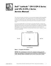
... open nearly 180 degrees. back of computer left side right side front of the display assembly with respect to the bottom case should never be replaced by performing the removal procedure in this manual, the locations or directions relative to exceed 180 degrees. The angle of computer support.dell.com Dell Latitude CPt V/CPt S Series and CPx H/CPx J Series Service Manual 1 This manual provides instructions for removing and replacing field-replaceable...
... open nearly 180 degrees. back of computer left side right side front of the display assembly with respect to the bottom case should never be replaced by performing the removal procedure in this manual, the locations or directions relative to exceed 180 degrees. The angle of computer support.dell.com Dell Latitude CPt V/CPt S Series and CPx H/CPx J Series Service Manual 1 This manual provides instructions for removing and replacing field-replaceable...
Service Manual
Page 10
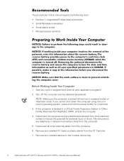
... is turned off the computer and any work in progress and close all other external cables from their electrical outlets to -disk or hibernate mode. Also disconnect any installed PC Cards or plastic blanks from the computer. 5. Remove any telephone or telecommunications lines from the PC Card slot. 7. NOTE: Make sure the computer is docked in the modular device bay. 2 Dell Latitude CPt V/CPt S Series and CPx H/CPx J Series Service Manual...
... is turned off the computer and any work in progress and close all other external cables from their electrical outlets to -disk or hibernate mode. Also disconnect any installed PC Cards or plastic blanks from the computer. 5. Remove any telephone or telecommunications lines from the PC Card slot. 7. NOTE: Make sure the computer is docked in the modular device bay. 2 Dell Latitude CPt V/CPt S Series and CPx H/CPx J Series Service Manual...
Service Manual
Page 14
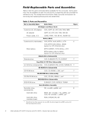
... 7 Hard-disk drive, HD, xxxxGB, yyMM, zzz* 6 subassembly Hard-disk drive MOD, HD, xxxxGB, I, F2, yyMM, zzz* CUS, HD xxxxGB, I, yyMM, zzz* Hard-disk drive interface board PWA, INTERCON, HD * Substitute the drive capacity for xxxxGB, the drive height for yyMM, and zzz for the computer. Customer kit, AC adapter AC adapter Power cable, U.S. Table 2 lists the parts and assemblies available for the manufacturer's name. 6 Dell Latitude CPt V/CPt S Series and CPx H/CPx J Series Service Manual
... 7 Hard-disk drive, HD, xxxxGB, yyMM, zzz* 6 subassembly Hard-disk drive MOD, HD, xxxxGB, I, F2, yyMM, zzz* CUS, HD xxxxGB, I, yyMM, zzz* Hard-disk drive interface board PWA, INTERCON, HD * Substitute the drive capacity for xxxxGB, the drive height for yyMM, and zzz for the computer. Customer kit, AC adapter AC adapter Power cable, U.S. Table 2 lists the parts and assemblies available for the manufacturer's name. 6 Dell Latitude CPt V/CPt S Series and CPx H/CPx J Series Service Manual
Service Manual
Page 15
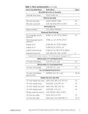
..., BZL, LCD, TFT, 14.1 12.1-inch display top cover ASSY, CVR, TOP, LCD, 12.1 12.1-inch display bezel ASSY, BZL, LCD, 12.1 Display assembly screws SCR, M2.5x4, PHH, LP, ZPS 14.1-inch flex cable ASSY, CBL, FLX, TFT 12.1-inch flex cable ASSY, CBL, FLX, W/EXTN,12.1 14 14 16 16 14 16, 17 support.dell.com Dell Latitude CPt V/CPt S Series and CPx H/CPx J Series Service Manual 7
..., BZL, LCD, TFT, 14.1 12.1-inch display top cover ASSY, CVR, TOP, LCD, 12.1 12.1-inch display bezel ASSY, BZL, LCD, 12.1 Display assembly screws SCR, M2.5x4, PHH, LP, ZPS 14.1-inch flex cable ASSY, CBL, FLX, TFT 12.1-inch flex cable ASSY, CBL, FLX, W/EXTN,12.1 14 14 16 16 14 16, 17 support.dell.com Dell Latitude CPt V/CPt S Series and CPx H/CPx J Series Service Manual 7
Service Manual
Page 18
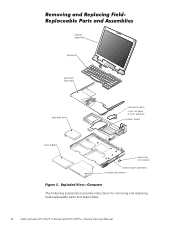
display assembly keyboard palmrest assembly hard-disk drive internal modem (may not apply to your system) system board main battery case plug for modem bottom case assembly modular bay device The following subsections provide instructions for removing and replacing field-replaceable parts and assemblies. 10 Dell Latitude CPt V/CPt S Series and CPx H/CPx J Series Service Manual
display assembly keyboard palmrest assembly hard-disk drive internal modem (may not apply to your system) system board main battery case plug for modem bottom case assembly modular bay device The following subsections provide instructions for removing and replacing field-replaceable parts and assemblies. 10 Dell Latitude CPt V/CPt S Series and CPx H/CPx J Series Service Manual
Service Manual
Page 21
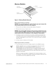
... have one memory module, install it in only one way. NOTES: 192-MB memory modules are notched so that the memory module is inserted with the double-stacked memory chips facing down does not fit properly in the socket. support.dell.com Dell Latitude CPt V/CPt S Series and CPx H/CPx J Series Service Manual 13 Remove the main battery and secondary battery (if present). 2. Remove the memory module cover. 3. If you . The slots on the system board are...
... have one memory module, install it in only one way. NOTES: 192-MB memory modules are notched so that the memory module is inserted with the double-stacked memory chips facing down does not fit properly in the socket. support.dell.com Dell Latitude CPt V/CPt S Series and CPx H/CPx J Series Service Manual 13 Remove the main battery and secondary battery (if present). 2. Remove the memory module cover. 3. If you . The slots on the system board are...
Service Manual
Page 22
... memory module down on a flat work surface. 10-mm screws (7) M2.5x10 14 Dell Latitude CPt V/CPt S Series and CPx H/CPx J Series Service Manual With the module at a 45-degree angle, press the memory module's edge connector firmly into place. If you do not hear a click as each end of the memory module socket. Close the display assembly, and turn the computer upside down until it . 4. Align the memory module...
... memory module down on a flat work surface. 10-mm screws (7) M2.5x10 14 Dell Latitude CPt V/CPt S Series and CPx H/CPx J Series Service Manual With the module at a 45-degree angle, press the memory module's edge connector firmly into place. If you do not hear a click as each end of the memory module socket. Close the display assembly, and turn the computer upside down until it . 4. Align the memory module...
Service Manual
Page 27
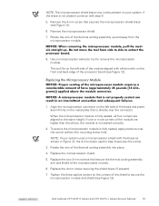
...Figure 12). 1. Replace the microprocessor shield. 5. Remove the microprocessor shield. 7. Replace the 4-mm screw securing the shield brace (if present). 7. Tighten the three captive screws on the corners of the processor board (see Figure 12). 6. support.dell.com Dell Latitude CPt V/CPt S Series and CPx H/CPx J Series Service Manual 19 NOTE: If... to secure the microprocessor module and shield (see Figure 12). NOTE: The microprocessor shield brace may not be present on your system uses a microprocessor shield with the brace as shown in Figure 12, the 4-mm screw used in step 6 secures ...
...Figure 12). 1. Replace the microprocessor shield. 5. Remove the microprocessor shield. 7. Replace the 4-mm screw securing the shield brace (if present). 7. Tighten the three captive screws on the corners of the processor board (see Figure 12). 6. support.dell.com Dell Latitude CPt V/CPt S Series and CPx H/CPx J Series Service Manual 19 NOTE: If... to secure the microprocessor module and shield (see Figure 12). NOTE: The microprocessor shield brace may not be present on your system uses a microprocessor shield with the brace as shown in Figure 12, the 4-mm screw used in step 6 secures ...
Service Manual
Page 28
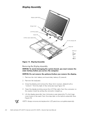
... remove and replace the LCD panel as a complete assembly. 20 Dell Latitude CPt V/CPt S Series and CPx H/CPx J Series Service Manual Remove the keyboard. 3. Close the display and remove the three 4-mm screws, labeled with a "circle D," from the snap tabs on the system board by pulling the connector straight up. 5. Pry the hinge cover loose at the seam from the back of the computer (see Figure 13). Open the display...
... remove and replace the LCD panel as a complete assembly. 20 Dell Latitude CPt V/CPt S Series and CPx H/CPx J Series Service Manual Remove the keyboard. 3. Close the display and remove the three 4-mm screws, labeled with a "circle D," from the snap tabs on the system board by pulling the connector straight up. 5. Pry the hinge cover loose at the seam from the back of the computer (see Figure 13). Open the display...
Service Manual
Page 42
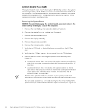
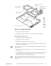
... service tag number, which is also visible on a bar-code label on the bottom of the microprocessor module. Remove the two screws securing the system board assembly (see Figure 22). 34 Dell Latitude CPt V/CPt S Series and CPx H/CPx J Series Service Manual Remove the palmrest assembly. 6. Remove the main battery and secondary battery (if present). 2. Locate and remove the 4-mm screw with washer that an optional modem is not present. Remove the device...
... service tag number, which is also visible on a bar-code label on the bottom of the microprocessor module. Remove the two screws securing the system board assembly (see Figure 22). 34 Dell Latitude CPt V/CPt S Series and CPx H/CPx J Series Service Manual Remove the palmrest assembly. 6. Remove the main battery and secondary battery (if present). 2. Locate and remove the 4-mm screw with washer that an optional modem is not present. Remove the device...
Service Manual
Page 43
.... Install the replacement system board. 2. support.dell.com Dell Latitude CPt V/CPt S Series and CPx H/CPx J Series Service Manual 35 Replace the microprocessor, the palmrest assembly, the display assembly and the keyboard assembly. NOTE: After replacing the system board assembly, be sure to the replacement system board assembly. 5. Remove the modem (if present). 11. Replace the modem (if present). 3. NOTE: Be sure to transfer the memory module(s) to enter the system's service tag number into the appropriate drive...
.... Install the replacement system board. 2. support.dell.com Dell Latitude CPt V/CPt S Series and CPx H/CPx J Series Service Manual 35 Replace the microprocessor, the palmrest assembly, the display assembly and the keyboard assembly. NOTE: After replacing the system board assembly, be sure to the replacement system board assembly. 5. Remove the modem (if present). 11. Replace the modem (if present). 3. NOTE: Be sure to transfer the memory module(s) to enter the system's service tag number into the appropriate drive...
Service Manual
Page 48
hard-disk drive assembly removal, 11 reserve battery removal, 32 inverter, 12.1-inch LCD panel removal, 26 replacement, 27 keyboard assembly removal, 15 memory module removal, 13 memory module cover removal, 12 microprocessor module removal, 18 modular bay devices removal, 12 module latch assemblies removal, 37 screw identification and tightening, 3 sockets memory module, 13 SuperDisk LS-120 drive removal, 12 system board assembly removal, 18 thermal cooling assembly removal, 36 tools, 2 travel module removal, 12 ZIF connectors, 5 palmrest assembly removal, 30 2 Dell Latitude CPt V/CPt S...
hard-disk drive assembly removal, 11 reserve battery removal, 32 inverter, 12.1-inch LCD panel removal, 26 replacement, 27 keyboard assembly removal, 15 memory module removal, 13 memory module cover removal, 12 microprocessor module removal, 18 modular bay devices removal, 12 module latch assemblies removal, 37 screw identification and tightening, 3 sockets memory module, 13 SuperDisk LS-120 drive removal, 12 system board assembly removal, 18 thermal cooling assembly removal, 36 tools, 2 travel module removal, 12 ZIF connectors, 5 palmrest assembly removal, 30 2 Dell Latitude CPt V/CPt S...
System Information Guide (multilanguage: English, Japanese, Chinese-Traditional, Chinese-Simplified, Korean, Thai)
Page 5
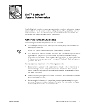
... to describe changes to your computer or software. Preliminary 1/25/00 Dell Latitude System Information 1-1 NOTE: The Getting Started placemat is located on your computer's back panel. This documentation includes information that are available and how to obtain them. support.dell.com DELL CONFIDENTIAL - Always read these updates before consulting any options you need to configure and install these options in all regions. • The User's Guide, which...
... to describe changes to your computer or software. Preliminary 1/25/00 Dell Latitude System Information 1-1 NOTE: The Getting Started placemat is located on your computer's back panel. This documentation includes information that are available and how to obtain them. support.dell.com DELL CONFIDENTIAL - Always read these updates before consulting any options you need to configure and install these options in all regions. • The User's Guide, which...
System Information Guide (multilanguage: English, Japanese, Chinese-Traditional, Chinese-Simplified, Korean, Thai)
Page 6
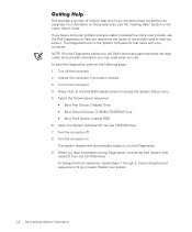
... to access the online User's Guide, use the Dell Diagnostics to help you determine the cause of tools to help you if your computer. To start the Diagnostics, perform the following boot sequence: • Boot First Device: Diskette Drive • Boot Second Device: CDROM / DVDROM Drive • Boot Third Device: Internal HDD 6. (Rev. 11/3/98) FILE LOCATION: \\Pd-xuzhan\d\FrameMaker\Dell\sndmm003\en\999CCA00en.fm Dell provides a number of the problem and...
... to access the online User's Guide, use the Dell Diagnostics to help you determine the cause of tools to help you if your computer. To start the Diagnostics, perform the following boot sequence: • Boot First Device: Diskette Drive • Boot Second Device: CDROM / DVDROM Drive • Boot Third Device: Internal HDD 6. (Rev. 11/3/98) FILE LOCATION: \\Pd-xuzhan\d\FrameMaker\Dell\sndmm003\en\999CCA00en.fm Dell provides a number of the problem and...
System Information Guide (multilanguage: English, Japanese, Chinese-Traditional, Chinese-Simplified, Korean, Thai)
Page 11
... disconnect any cables or perform maintenance or reconfiguration of this document. (Rev. 11/3/98) FILE LOCATION: \\Pd-xuzhan\d\FrameMaker\Dell\sndmm003\en\999CCA00en.fm • Place the AC adapter in a ventilated area, such as a desk top or on a level surface. They may become very warm during normal operation. Use care when removing PC Cards after their continuous operation. • Do...
... disconnect any cables or perform maintenance or reconfiguration of this document. (Rev. 11/3/98) FILE LOCATION: \\Pd-xuzhan\d\FrameMaker\Dell\sndmm003\en\999CCA00en.fm • Place the AC adapter in a ventilated area, such as a desk top or on a level surface. They may become very warm during normal operation. Use care when removing PC Cards after their continuous operation. • Do...
System Information Guide (multilanguage: English, Japanese, Chinese-Traditional, Chinese-Simplified, Korean, Thai)
Page 12
... your computer, battery, and hard-disk drive from environmental hazards such as cloth or paper. Apply the cleaner to install the drive in a nonconducting material, such as dirt, dust, food, liquids, temperature extremes, and overexposure to evaporate before you connect a cable make sure both connectors are asked to turn it off the computer before removing the memory module or disconnecting the device to help...
... your computer, battery, and hard-disk drive from environmental hazards such as cloth or paper. Apply the cleaner to install the drive in a nonconducting material, such as dirt, dust, food, liquids, temperature extremes, and overexposure to evaporate before you connect a cable make sure both connectors are asked to turn it off the computer before removing the memory module or disconnecting the device to help...

System Information Guide (multilanguage: English, Japanese, Chinese-Traditional, Chinese-Simplified, Korean, Thai)
Page 15
... to remove any of these ways: • Use suspend mode Place the computer in suspend mode by touching an unpainted metal surface on an external keyboard if the External Hot Key option is enabled in the battery bay, perform the following notice may appear throughout your body may have accumulated. You can also take the following steps to remind you touch any static charge your Dell...
... to remove any of these ways: • Use suspend mode Place the computer in suspend mode by touching an unpainted metal surface on an external keyboard if the External Hot Key option is enabled in the battery bay, perform the following notice may appear throughout your body may have accumulated. You can also take the following steps to remind you touch any static charge your Dell...
System Information Guide (multilanguage: English, Japanese, Chinese-Traditional, Chinese-Simplified, Korean, Thai)
Page 22
... - The grant of a Telepermit for connection to its network. If a charge for local calls is unacceptable, the 'Dial' button should be set up to make or model, nor does it imply that any sort of the local number should not be used in conjunction with minimum conditions for any item of terminal equipment indicates only that Telecom has accepted that...
... - The grant of a Telepermit for connection to its network. If a charge for local calls is unacceptable, the 'Dial' button should be set up to make or model, nor does it imply that any sort of the local number should not be used in conjunction with minimum conditions for any item of terminal equipment indicates only that Telecom has accepted that...


