
Service Manual
Page 5
... Parts and Assemblies 6 Removing and Replacing Field-Replaceable Parts and Assemblies 10 Hard-Disk Drive Assembly 11 Removing the Hard-Disk Drive Assembly 11 Replacing the Hard-Disk Drive Assembly 11 Modular Bay Devices (Diskette Drive, CD-ROM Drive, DVD-ROM Drive, CD-RW Drive, SuperDisk LS-120 Drive, Battery, or Travel Module) . . . . 12 Memory Module Cover 12 Removing the Memory...
... Parts and Assemblies 6 Removing and Replacing Field-Replaceable Parts and Assemblies 10 Hard-Disk Drive Assembly 11 Removing the Hard-Disk Drive Assembly 11 Replacing the Hard-Disk Drive Assembly 11 Modular Bay Devices (Diskette Drive, CD-ROM Drive, DVD-ROM Drive, CD-RW Drive, SuperDisk LS-120 Drive, Battery, or Travel Module) . . . . 12 Memory Module Cover 12 Removing the Memory...
Service Manual
Page 6
... 13. Figure 5. Figure 19. Figure 9. Figure 16. Computer Orientation 1 Main Battery Removal 3 Screw Identification 3 Disconnecting a Cable from an Interface Connector 5 Exploded View-Computer 10 Hard-Disk Drive Assembly Removal 11 Modular Bay Device Removal 12 Memory Module Removal 13 Removing the Keyboard Assembly Screws 14 Keyboard Assembly Removal 15 Keyboard and Track...
... 13. Figure 5. Figure 19. Figure 9. Figure 16. Computer Orientation 1 Main Battery Removal 3 Screw Identification 3 Disconnecting a Cable from an Interface Connector 5 Exploded View-Computer 10 Hard-Disk Drive Assembly Removal 11 Modular Bay Device Removal 12 Memory Module Removal 13 Removing the Keyboard Assembly Screws 14 Keyboard Assembly Removal 15 Keyboard and Track...
Service Manual
Page 12
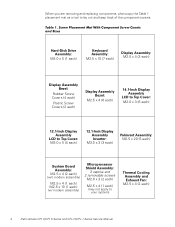
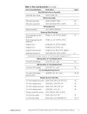
Hard-Disk Drive Assembly: M3.0 x 5 (1 each) Keyboard Assembly: M2.5 x 10 (7 each) Display Assembly: M2.5 x 4 (3 each) Display Assembly Bezel: Rubber Screw Covers (4 each) Plastic Screw Covers (2 ...: M2.5 x 4 (2 each) (w/o modem assembly) M2.5 x 4 (1 each) M2.5 x 10 (1 each) (w/ modem assembly) Microprocessor Shield Assembly: 3 captive and 2 removable screws M2.0 x 3 (2 each) M2.5 x 4 (1 each ) 4 Dell Latitude CPt V/CPt S Series and CPx H/CPx J Series Service Manual When you are removing and replacing components, photocopy the Table 1 placement mat as a tool to your system) Thermal...
Hard-Disk Drive Assembly: M3.0 x 5 (1 each) Keyboard Assembly: M2.5 x 10 (7 each) Display Assembly: M2.5 x 4 (3 each) Display Assembly Bezel: Rubber Screw Covers (4 each) Plastic Screw Covers (2 ...: M2.5 x 4 (2 each) (w/o modem assembly) M2.5 x 4 (1 each) M2.5 x 10 (1 each) (w/ modem assembly) Microprocessor Shield Assembly: 3 captive and 2 removable screws M2.0 x 3 (2 each) M2.5 x 4 (1 each ) 4 Dell Latitude CPt V/CPt S Series and CPx H/CPx J Series Service Manual When you are removing and replacing components, photocopy the Table 1 placement mat as a tool to your system) Thermal...
Service Manual
Page 14
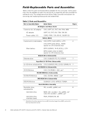
...* CUS, HD xxxxGB, I, yyMM, zzz* Hard-disk drive interface board PWA, INTERCON, HD * Substitute the drive capacity for xxxxGB, the drive height for yyMM, and zzz for reference only. Some parts may only be available as part of a service kit or assembly and are provided for the manufacturer's name. 6 Dell Latitude CPt V/CPt S Series and CPx H/CPx J Series...
...* CUS, HD xxxxGB, I, yyMM, zzz* Hard-disk drive interface board PWA, INTERCON, HD * Substitute the drive capacity for xxxxGB, the drive height for yyMM, and zzz for reference only. Some parts may only be available as part of a service kit or assembly and are provided for the manufacturer's name. 6 Dell Latitude CPt V/CPt S Series and CPx H/CPx J Series...
Service Manual
Page 15
Hard-disk drive carrier ASSY, CARR, HD Palmrest assembly ASSY, PLMRST, TPAD 20 Palmrest screws (5) SCR, M2.5X20, PHH, LP, ZPS 19 Reserve battery CUS, BTRY, RESERVE Euro-... 14.1-inch flex cable ASSY, CBL, FLX, TFT 12.1-inch flex cable ASSY, CBL, FLX, W/EXTN,12.1 14 14 16 16 14 16, 17 support.dell.com Dell Latitude CPt V/CPt S Series and CPx H/CPx J Series Service Manual 7
Hard-disk drive carrier ASSY, CARR, HD Palmrest assembly ASSY, PLMRST, TPAD 20 Palmrest screws (5) SCR, M2.5X20, PHH, LP, ZPS 19 Reserve battery CUS, BTRY, RESERVE Euro-... 14.1-inch flex cable ASSY, CBL, FLX, TFT 12.1-inch flex cable ASSY, CBL, FLX, W/EXTN,12.1 14 14 16 16 14 16, 17 support.dell.com Dell Latitude CPt V/CPt S Series and CPx H/CPx J Series Service Manual 7
Service Manual
Page 18
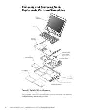
display assembly keyboard palmrest assembly hard-disk drive internal modem (may not apply to your system) system board main battery case plug for modem bottom case assembly modular bay device The following subsections provide instructions for removing and replacing field-replaceable parts and assemblies. 10 Dell Latitude CPt V/CPt S Series and CPx H/CPx J Series Service Manual
display assembly keyboard palmrest assembly hard-disk drive internal modem (may not apply to your system) system board main battery case plug for modem bottom case assembly modular bay device The following subsections provide instructions for removing and replacing field-replaceable parts and assemblies. 10 Dell Latitude CPt V/CPt S Series and CPx H/CPx J Series Service Manual
Service Manual
Page 19
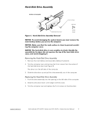
... present). 2. Slide the drive door up and pull the drive assembly out of computer 5-mm screw M3.0x5 hard-disk drive door 1. Turn the computer over , and remove the 5-mm screw from the center of the hard-disk drive door (see Figure 6). Slide the drive door down until it aligns...computer. 1. Turn the computer over and replace the 5-mm screw on the drive door. The drive is on the left side of the computer. 2. Push the drive assembly into the opening on the left side of the computer. 3. support.dell.com Dell Latitude CPt V/CPt S Series and CPx H/CPx J Series Service Manual 11
... present). 2. Slide the drive door up and pull the drive assembly out of computer 5-mm screw M3.0x5 hard-disk drive door 1. Turn the computer over , and remove the 5-mm screw from the center of the hard-disk drive door (see Figure 6). Slide the drive door down until it aligns...computer. 1. Turn the computer over and replace the 5-mm screw on the drive door. The drive is on the left side of the computer. 2. Push the drive assembly into the opening on the left side of the computer. 3. support.dell.com Dell Latitude CPt V/CPt S Series and CPx H/CPx J Series Service Manual 11
Service Manual
Page 42
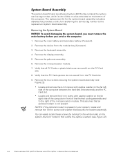
... to the right of the computer between the hard-disk drive assembly and the PC Card slot. Verify that all PC Cards or plastic blanks are removed from the PC Card slot. 8. Remove the two screws securing the system board assembly (see Figure 22). 34 Dell Latitude CPt V/CPt S Series and CPx H/CPx J Series Service Manual...
... to the right of the computer between the hard-disk drive assembly and the PC Card slot. Verify that all PC Cards or plastic blanks are removed from the PC Card slot. 8. Remove the two screws securing the system board assembly (see Figure 22). 34 Dell Latitude CPt V/CPt S Series and CPx H/CPx J Series Service Manual...
Service Manual
Page 48
hard-disk drive assembly removal, 11 reserve battery removal, 32 inverter, 12.1-inch LCD panel removal, 26 replacement, 27 keyboard assembly removal, 15 memory module removal, 13 memory ... bay devices removal, 12 module latch assemblies removal, 37 screw identification and tightening, 3 sockets memory module, 13 SuperDisk LS-120 drive removal, 12 system board assembly removal, 18 thermal cooling assembly removal, 36 tools, 2 travel module removal, 12 ZIF connectors, 5 palmrest assembly removal, 30 2 Dell Latitude CPt V/CPt S Series and CPx H/Cpx J Series Service Manual
hard-disk drive assembly removal, 11 reserve battery removal, 32 inverter, 12.1-inch LCD panel removal, 26 replacement, 27 keyboard assembly removal, 15 memory module removal, 13 memory ... bay devices removal, 12 module latch assemblies removal, 37 screw identification and tightening, 3 sockets memory module, 13 SuperDisk LS-120 drive removal, 12 system board assembly removal, 18 thermal cooling assembly removal, 36 tools, 2 travel module removal, 12 ZIF connectors, 5 palmrest assembly removal, 30 2 Dell Latitude CPt V/CPt S Series and CPx H/Cpx J Series Service Manual
System Information Guide (multilanguage: English, Japanese, Chinese-Traditional, Chinese-Simplified, Korean, Thai)
Page 5
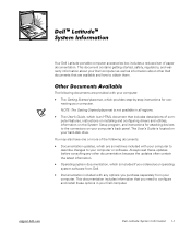
... contain the latest information. • Operating system documentation, which is located on your Dell computer as well as information about your hard-disk drive. (Rev. 11/3/98) FILE LOCATION: \\Pd-xuzhan\d\FrameMaker\Dell\sndmm003\en\999CCA00en.fm ™ ™ Your Dell Latitude portable computer accessories box includes a reduced set of the following documents are available and...
... contain the latest information. • Operating system documentation, which is located on your Dell computer as well as information about your hard-disk drive. (Rev. 11/3/98) FILE LOCATION: \\Pd-xuzhan\d\FrameMaker\Dell\sndmm003\en\999CCA00en.fm ™ ™ Your Dell Latitude portable computer accessories box includes a reduced set of the following documents are available and...
System Information Guide (multilanguage: English, Japanese, Chinese-Traditional, Chinese-Simplified, Korean, Thai)
Page 10
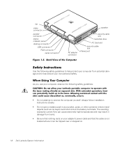
... • Do not carry a battery pack in damage from potential damage and to service the computer yourself. DELL CONFIDENTIAL - Preliminary 1/25/00 1-6 Dell Latitude System Information As you use your computer, observe the following safety guidelines to help ensure your own personal safety.../3/98) FILE LOCATION: \\Pd-xuzhan\d\FrameMaker\Dell\sndmm003\en\999CCA00en.fm fan video connector parallel connector status indicator panel docking connector USB connector PS/2 connector serial connector speaker security cable slot hard-disk drive PC Card slot AC adapter connector security cable...
... • Do not carry a battery pack in damage from potential damage and to service the computer yourself. DELL CONFIDENTIAL - Preliminary 1/25/00 1-6 Dell Latitude System Information As you use your computer, observe the following safety guidelines to help ensure your own personal safety.../3/98) FILE LOCATION: \\Pd-xuzhan\d\FrameMaker\Dell\sndmm003\en\999CCA00en.fm fan video connector parallel connector status indicator panel docking connector USB connector PS/2 connector serial connector speaker security cable slot hard-disk drive PC Card slot AC adapter connector security cable...
System Information Guide (multilanguage: English, Japanese, Chinese-Traditional, Chinese-Simplified, Korean, Thai)
Page 12
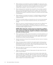
...Also, before you pull out the connector, keep it evenly aligned to avoid bending any connector pins. Preliminary 1/25/00 1-8 Dell Latitude System Information If you have the drive checked by hand, be sure to have the computer checked by its edges, not its pins. • When removing a...turn it could slide around. If the display contains grease or some other mechanical shocks. • Protect your computer, battery, and hard-disk drive from its strain-relief loop, not on the computer. • When traveling with very different temperature and/or humidity ranges, condensation ...
...Also, before you pull out the connector, keep it evenly aligned to avoid bending any connector pins. Preliminary 1/25/00 1-8 Dell Latitude System Information If you have the drive checked by hand, be sure to have the computer checked by its edges, not its pins. • When removing a...turn it could slide around. If the display contains grease or some other mechanical shocks. • Protect your computer, battery, and hard-disk drive from its strain-relief loop, not on the computer. • When traveling with very different temperature and/or humidity ranges, condensation ...


