Service Manual
Page 4
... of the Computer 1-3 Indicator Panel 1-4 Battery Indicator 3-4 Computer Orientation 4-1 Main Battery Assembly Removal 4-3 vi Figure 4-2. Figure 1-2. Figure 4-1. Figure 1-4. Hard-Disk Drive Assembly 4-15 Memory Module Cover 4-16 Memory Modules 4-17 Keyboard Assembly 4-18 Back Cover Assembly 4-20 Palmrest Assembly 4-21 Touch-Pad Interface Module 4-23 Power Button 4-24 Display Assembly Components 4-25...
... of the Computer 1-3 Indicator Panel 1-4 Battery Indicator 3-4 Computer Orientation 4-1 Main Battery Assembly Removal 4-3 vi Figure 4-2. Figure 1-2. Figure 4-1. Figure 1-4. Hard-Disk Drive Assembly 4-15 Memory Module Cover 4-16 Memory Modules 4-17 Keyboard Assembly 4-18 Back Cover Assembly 4-20 Palmrest Assembly 4-21 Touch-Pad Interface Module 4-23 Power Button 4-24 Display Assembly Components 4-25...
Service Manual
Page 5
... 4-33. Table 4-1. Figure 4-6. Figure 4-19. Figure 4-24. Screw Identification 4-3 Disconnecting an Interface Cable 4-4 Exploded View-Computer 4-14 Hard-Disk Drive Assembly Removal 4-15 Memory Module Cover Removal 4-16 Memory Module Removal 4-17 Removing the Keyboard Assembly Screws 4-18 Keyboard Assembly Removal 4-19 Back Cover Assembly Removal 4-20 Palmrest Assembly Removal 4-21 Touch...
... 4-33. Table 4-1. Figure 4-6. Figure 4-19. Figure 4-24. Screw Identification 4-3 Disconnecting an Interface Cable 4-4 Exploded View-Computer 4-14 Hard-Disk Drive Assembly Removal 4-15 Memory Module Cover Removal 4-16 Memory Module Removal 4-17 Removing the Keyboard Assembly Screws 4-18 Keyboard Assembly Removal 4-19 Back Cover Assembly Removal 4-20 Palmrest Assembly Removal 4-21 Touch...
Service Manual
Page 7
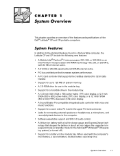
This chapter provides an overview of the features and specifications of system memory. A 512-KB or 256-KB pipelined-burst SRAM external cache. Support for 32-bit data transfer. A lithium ion battery with voice and music functions... Support for connecting external speakers or headphones, a microphone, and record/playback devices to the computer. In addition to 128 MB of the Dell® Latitude® CP and CPi portable computers. A Sound Blaster Pro-compatible integrated audio controller with a built-in charge gauge and ExpressCharge technology that supports the CardBus standard for...
This chapter provides an overview of the features and specifications of system memory. A 512-KB or 256-KB pipelined-burst SRAM external cache. Support for 32-bit data transfer. A lithium ion battery with voice and music functions... Support for connecting external speakers or headphones, a microphone, and record/playback devices to the computer. In addition to 128 MB of the Dell® Latitude® CP and CPi portable computers. A Sound Blaster Pro-compatible integrated audio controller with a built-in charge gauge and ExpressCharge technology that supports the CardBus standard for...
Service Manual
Page 8
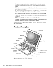
... system features, see "Technical Specifications" found later in this chapter. Hardware and software support for the Dell Latitude C/Port Advanced Port Replicator (APR) and Latitude C/Dock Expansion Station. display microphone power button keyboard touch pad battery bay touch pad buttons (2) modular bay...adapter connector audio jacks (3) speakers (2) 1-2 Dell Latitude CP and CPi Service Manual A PC Card slot with IrDA 1.1 (Fast IR) and 1.0 standards, and a USB connector that help you conserve battery power. A BIOS that resides in flash memory and that slows the microprocessor or starts ...
... system features, see "Technical Specifications" found later in this chapter. Hardware and software support for the Dell Latitude C/Port Advanced Port Replicator (APR) and Latitude C/Dock Expansion Station. display microphone power button keyboard touch pad battery bay touch pad buttons (2) modular bay...adapter connector audio jacks (3) speakers (2) 1-2 Dell Latitude CP and CPi Service Manual A PC Card slot with IrDA 1.1 (Fast IR) and 1.0 standards, and a USB connector that help you conserve battery power. A BIOS that resides in flash memory and that slows the microprocessor or starts ...
Service Manual
Page 9
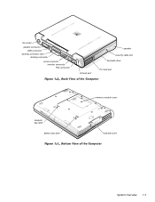
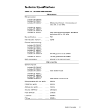
fan outlet parallel connector USB connector docking connector door docking connector serial connector monitor connector PS2 connector infrared port speaker security cable slot hard-disk drive PC Card slot modular bay latch battery bay latch memory module cover hard-disk drive System Overview 1-3
fan outlet parallel connector USB connector docking connector door docking connector serial connector monitor connector PS2 connector infrared port speaker security cable slot hard-disk drive PC Card slot modular bay latch battery bay latch memory module cover hard-disk drive System Overview 1-3
Service Manual
Page 13
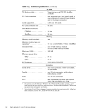
... Internal cache memory 32 KB External cache memory: Latitude CPi D300XT Latitude CPi D266XT Latitude CPi D233ST Latitude CP M233XT Latitude CP M233ST Latitude CP M233SD 512 KB pipelined-burst SRAM Latitude CP M166ST 256 KB pipelined-burst SRAM Math coprocessor internal to the microprocessor System chip set: Latitude CPi D300XT Latitude CPi D266XT Latitude CPi D233ST Intel 440BX PCIset Latitude CP M233XT Latitude CP M233ST Latitude CP M233SD Latitude CP M166ST...
... Internal cache memory 32 KB External cache memory: Latitude CPi D300XT Latitude CPi D266XT Latitude CPi D233ST Latitude CP M233XT Latitude CP M233ST Latitude CP M233SD 512 KB pipelined-burst SRAM Latitude CP M166ST 256 KB pipelined-burst SRAM Math coprocessor internal to the microprocessor System chip set: Latitude CPi D300XT Latitude CPi D266XT Latitude CPi D233ST Intel 440BX PCIset Latitude CP M233XT Latitude CP M233ST Latitude CP M233SD Latitude CP M166ST...
Service Manual
Page 14
... type and capacities2 16-, 32-, and 64-MB 3.3-V EDO SODIMMs Standard RAM one 16-MB memory module or one 32-MB memory module Maximum RAM 128 MB Memory access time: tRAC 60 ns tCAC 15 ns BIOS address F000:0000-F000:FFFF Serial (DTE one 9-pin connector; ... ® 4.0 operating system does not support zoom video. 2 The Latitude CP and CPi do not support memory modules from previous models of Dell portable computers, such as the Latitude XP, XPi, XPi CD, and LM. 1-8 Dell Latitude CP and CPi Service Manual PC Card controller Texas Instruments PCI1131 CardBus controller PC Card connectors...
... type and capacities2 16-, 32-, and 64-MB 3.3-V EDO SODIMMs Standard RAM one 16-MB memory module or one 32-MB memory module Maximum RAM 128 MB Memory access time: tRAC 60 ns tCAC 15 ns BIOS address F000:0000-F000:FFFF Serial (DTE one 9-pin connector; ... ® 4.0 operating system does not support zoom video. 2 The Latitude CP and CPi do not support memory modules from previous models of Dell portable computers, such as the Latitude XP, XPi, XPi CD, and LM. 1-8 Dell Latitude CP and CPi Service Manual PC Card controller Texas Instruments PCI1131 CardBus controller PC Card connectors...
Service Manual
Page 15
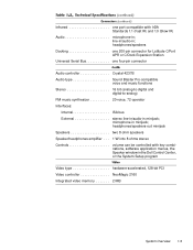
... 200-pin connector for Latitude C/Port APR or C/Dock Expansion Station Universal Serial Bus one port compatible with key combinations, software application menus, the Speaker window in the Dell Control Center, or the System Setup program Video type hardware-accelerated, 128-bit PCI Video controller NeoMagic 2160 Integrated video memory 2 MB System Overview...
... 200-pin connector for Latitude C/Port APR or C/Dock Expansion Station Universal Serial Bus one port compatible with key combinations, software application menus, the Speaker window in the Dell Control Center, or the System Setup program Video type hardware-accelerated, 128-bit PCI Video controller NeoMagic 2160 Integrated video memory 2 MB System Overview...
Service Manual
Page 19
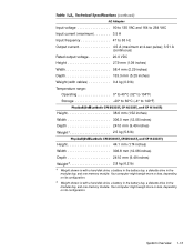
... less, depending on its configuration. 5 Weight shown is with a hard-disk drive, a battery in the battery bay, a diskette drive in the modular bay, and one memory module. Input voltage 90 to 135 VAC and 164 to 264 VAC Input current (maximum 3.5 A Input frequency 47 to 63 Hz Output current 4.5 A (maximum at... (9.49 inches) Weight5 2.8 kg (6.2 lb) 4 Weight shown is with a hard-disk drive, a battery in the battery bay, a diskette drive in the modular bay, and one memory module.
... less, depending on its configuration. 5 Weight shown is with a hard-disk drive, a battery in the battery bay, a diskette drive in the modular bay, and one memory module. Input voltage 90 to 135 VAC and 164 to 264 VAC Input current (maximum 3.5 A Input frequency 47 to 63 Hz Output current 4.5 A (maximum at... (9.49 inches) Weight5 2.8 kg (6.2 lb) 4 Weight shown is with a hard-disk drive, a battery in the battery bay, a diskette drive in the modular bay, and one memory module.
Service Manual
Page 20
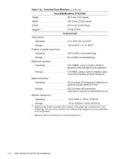
... more or less, depending on its configuration. 7 Measured with a hard-disk drive, a battery in the battery bay, a diskette drive in head-parked position. 1-14 Dell Latitude CP and CPi Service Manual Height 38.6 mm (1.52 inches) Width 306.0 mm (12.05 inches) Depth 241.0 mm (9.49 inches) Weight6 2.6 kg (5.8 lb) Temperature: Operating 0°... ft) Storage 18 to 10,600 m (-59 to 35,000 ft) 6 Weight shown is with the hard-disk drive in the modular bay, and one memory module.
... more or less, depending on its configuration. 7 Measured with a hard-disk drive, a battery in the battery bay, a diskette drive in head-parked position. 1-14 Dell Latitude CP and CPi Service Manual Height 38.6 mm (1.52 inches) Width 306.0 mm (12.05 inches) Depth 241.0 mm (9.49 inches) Weight6 2.6 kg (5.8 lb) Temperature: Operating 0°... ft) Storage 18 to 10,600 m (-59 to 35,000 ft) 6 Weight shown is with the hard-disk drive in the modular bay, and one memory module.
Service Manual
Page 26
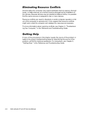
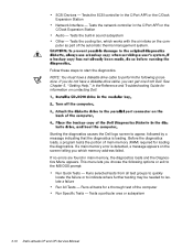
Because devices may require dedicated memory spaces, interrupt levels, or DMA channels, all of which must be installed at all. If none of the procedures in the Reference and Troubleshooting Guide. 2-6 Dell Latitude CP and CPi Service Manual For instructions, see Chapter 3, "Troubleshooting Your Computer," in disorderly or erratic computer operation or failure of the...
Because devices may require dedicated memory spaces, interrupt levels, or DMA channels, all of which must be installed at all. If none of the procedures in the Reference and Troubleshooting Guide. 2-6 Dell Latitude CP and CPi Service Manual For instructions, see Chapter 3, "Troubleshooting Your Computer," in disorderly or erratic computer operation or failure of the...
Service Manual
Page 28
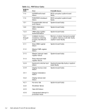
... failure Gate A20 failure Unexpected interrupt in protected mode 3-2 Dell Latitude CP and CPi Service Manual system board faulty BIOS corrupted; 1-1-3 1-1-4 1-2-1 1-2-2 1-2-3 1-3-1 through 1-1-1 3-1-1 3-1-2 3-1-3 3-1-4 3-2-4 3-3-4 3-4-1 3-4-2 4-2-1 4-2-2 4-2-3 4-2-4 NVRAM write/read failure ROM BIOS checksum failure Programmable interval timer failure DMA initialization failure DMA page register write/read failure Installed memory module(s) not being properly identified or used Slave DMA...
... failure Gate A20 failure Unexpected interrupt in protected mode 3-2 Dell Latitude CP and CPi Service Manual system board faulty BIOS corrupted; 1-1-3 1-1-4 1-2-1 1-2-2 1-2-3 1-3-1 through 1-1-1 3-1-1 3-1-2 3-1-3 3-1-4 3-2-4 3-3-4 3-4-1 3-4-2 4-2-1 4-2-2 4-2-3 4-2-4 NVRAM write/read failure ROM BIOS checksum failure Programmable interval timer failure DMA initialization failure DMA page register write/read failure Installed memory module(s) not being properly identified or used Slave DMA...
Service Manual
Page 29
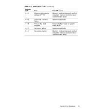
4-3-1 4-3-3 4-3-4 4-4-1 5-1-2 Memory failure above address 0FFFFh Timer chip counter 2 failure Time-of-day clock stopped Serial port failure No usable memory Memory module improperly seated or system memory controller faulty (system board faulty) System board faulty Reserve battery faulty or system board faulty System board faulty Memory module improperly seated or system memory controller faulty (system board faulty) System Error Messages 3-3
4-3-1 4-3-3 4-3-4 4-4-1 5-1-2 Memory failure above address 0FFFFh Timer chip counter 2 failure Time-of-day clock stopped Serial port failure No usable memory Memory module improperly seated or system memory controller faulty (system board faulty) System board faulty Reserve battery faulty or system board faulty System board faulty Memory module improperly seated or system memory controller faulty (system board faulty) System Error Messages 3-3
Service Manual
Page 31
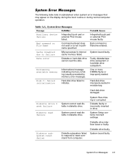
... faulty or incorrectly inserted in modular bay. System Error Messages 3-5 Command entered does not exist or is failing (usually preceded by memory error message). One or more DIMMs faulty or improperly seated. Hard-disk drive improperly seated in drive. System files missing or corrupted...subsystem reset failed Integrated touch pad or external PS/2 mouse failed. The following table lists (in pathname specified. Informational message indicating memory is not in alphabetical order) system error messages that may appear on the display during the boot routine or during normal computer...
... faulty or incorrectly inserted in modular bay. System Error Messages 3-5 Command entered does not exist or is failing (usually preceded by memory error message). One or more DIMMs faulty or improperly seated. Hard-disk drive improperly seated in drive. System files missing or corrupted...subsystem reset failed Integrated touch pad or external PS/2 mouse failed. The following table lists (in pathname specified. Informational message indicating memory is not in alphabetical order) system error messages that may appear on the display during the boot routine or during normal computer...

Service Manual
Page 32
... or controller not responding to commands from computer. Hard-disk drive not responding to commands from computer. Hard-disk drive faulty. 3-6 Dell Latitude CP and CPi Service Manual One or more memory modules faulty or improperly seated. Diskette writeprotected. Operating system unable to commands from or improperly installed in computer. PC Card faulty, improperly...
... or controller not responding to commands from computer. Hard-disk drive not responding to commands from computer. Hard-disk drive faulty. 3-6 Dell Latitude CP and CPi Service Manual One or more memory modules faulty or improperly seated. Diskette writeprotected. Operating system unable to commands from or improperly installed in computer. PC Card faulty, improperly...
Service Manual
Page 33
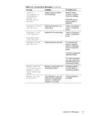
.... For external keyboard or keypad, cable or connector loose or keyboard faulty. Cable or connector loose, or keyboard faulty. Installed memory module faulty or improperly seated. System Error Messages 3-7 The software in keyboard, keyboard faulty. Cable or connector loose, or keyboard... faulty. For either keyboard, key may have been pressed while computer was booting. Memory address line failure at address, read value expecting value Memory allocation error Memory control logic not operating properly. System Setup program contains incorrect settings. For built-in use...
.... For external keyboard or keypad, cable or connector loose or keyboard faulty. Cable or connector loose, or keyboard faulty. Installed memory module faulty or improperly seated. System Error Messages 3-7 The software in keyboard, keyboard faulty. Cable or connector loose, or keyboard... faulty. For either keyboard, key may have been pressed while computer was booting. Memory address line failure at address, read value expecting value Memory allocation error Memory control logic not operating properly. System Setup program contains incorrect settings. For built-in use...

Service Manual
Page 34
... logic failure at address, read value expecting value Memory odd/even logic failure at address, read value expecting value Memory write/read failure at address, read value expecting value No boot device available No boot sector on diskette or ...address, read value expecting value Memory not operating properly. ROM in external device faulty. Installed memory module faulty or improperly seated. No operating system files on system board malfunctioning. No boot sector on diskette or hard-disk drive. 3-8 Dell Latitude CP and CPi Service Manual Bad sector or corrupted...
... logic failure at address, read value expecting value Memory odd/even logic failure at address, read value expecting value Memory write/read failure at address, read value expecting value No boot device available No boot sector on diskette or ...address, read value expecting value Memory not operating properly. ROM in external device faulty. Installed memory module faulty or improperly seated. No operating system files on system board malfunctioning. No boot sector on diskette or hard-disk drive. 3-8 Dell Latitude CP and CPi Service Manual Bad sector or corrupted...
Service Manual
Page 35
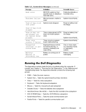
...2 failed Unexpected interrupt in troubleshooting the computer. Timer circuit on diskette or hard-disk drive. One or more memory module(s) faulty or improperly seated. The diagnostics contains tests that aid in protected mode Warning! Tests the system ...communication port Parallel Ports - If needed, see Chapter 4, "Running the Dell Diagnostics," in RTC does not match system clock. Keyboard/mouse controller malfunctioning, or memory module(s) not responding. Tests the main memory System Set - System board faulty. Tests the parallel communication port System Error...
...2 failed Unexpected interrupt in troubleshooting the computer. Timer circuit on diskette or hard-disk drive. One or more memory module(s) faulty or improperly seated. The diagnostics contains tests that aid in protected mode Warning! Tests the system ...communication port Parallel Ports - If needed, see Chapter 4, "Running the Dell Diagnostics," in RTC does not match system clock. Keyboard/mouse controller malfunctioning, or memory module(s) not responding. Tests the main memory System Set - System board faulty. Tests the parallel communication port System Error...
Service Manual
Page 36
...on the screen telling you do not have a diskette-drive cable to isolate a failure Run All Tests - Tests the network controller in main memory, the diagnostics loads and the Diagnostics Menu appears. See Chapter 5, "Getting Help," in the C/Port APR or the C/Dock Expansion Station ... controller in the Reference and Troubleshooting Guide for loading the diagnostics. SCSI Devices - Tests a particular area or subsystem 3-10 Dell Latitude CP and CPi Service Manual Tests the built-in sound subsystem Other - NOTE: You must have a diskette-drive cable, you choose the following procedure....
...on the screen telling you do not have a diskette-drive cable to isolate a failure Run All Tests - Tests the network controller in main memory, the diagnostics loads and the Diagnostics Menu appears. See Chapter 5, "Getting Help," in the C/Port APR or the C/Dock Expansion Station ... controller in the Reference and Troubleshooting Guide for loading the diagnostics. SCSI Devices - Tests a particular area or subsystem 3-10 Dell Latitude CP and CPi Service Manual Tests the built-in sound subsystem Other - NOTE: You must have a diskette-drive cable, you choose the following procedure....
Service Manual
Page 47
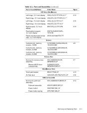
....1-inch display SWT,SUS,MGNT,DSPL, TFT/STN Plastic inverter-board screw SPCR,SCR,INVRTR,TFT caps, 12.1-inch display Customer kit, memory CUS,DIMM,16,60N,2X64,2K, 4-8 module, 16-MB 144,EDO,NBK Customer kit, memory module, 32-MB CUS,DIMM,32,60N,4X64,4K, 144,EDO,NBK Customer kit..., memory module, 64-MB CUS,DIMM,64,60N,8X64,4K, 144,EDO,NBK Service kit, memory door SVC,SUBASSY,DOOR, 4-7 assembly MEM/BIOS,CP Memory/BIOS door subassembly SUBASSY,DOOR, MEM/BIOS,NB,CP Touch-pad bracket Air flow duct...
....1-inch display SWT,SUS,MGNT,DSPL, TFT/STN Plastic inverter-board screw SPCR,SCR,INVRTR,TFT caps, 12.1-inch display Customer kit, memory CUS,DIMM,16,60N,2X64,2K, 4-8 module, 16-MB 144,EDO,NBK Customer kit, memory module, 32-MB CUS,DIMM,32,60N,4X64,4K, 144,EDO,NBK Customer kit..., memory module, 64-MB CUS,DIMM,64,60N,8X64,4K, 144,EDO,NBK Service kit, memory door SVC,SUBASSY,DOOR, 4-7 assembly MEM/BIOS,CP Memory/BIOS door subassembly SUBASSY,DOOR, MEM/BIOS,NB,CP Touch-pad bracket Air flow duct...


