Service Manual
Page 4
... of the Computer 1-3 Bottom View of the Computer 1-3 Indicator Panel 1-4 Battery Indicator 3-4 Computer Orientation 4-1 Main Battery Assembly Removal 4-3 vi Figure 4-2. Hard-Disk Drive Assembly 4-15 Memory Module Cover 4-16 Memory Modules 4-17 Keyboard Assembly 4-18 Back Cover Assembly 4-20 Palmrest Assembly 4-21 ... Cable 4-37 LCD Display Hinge 4-38 Display-Assembly Top Cover 4-39 Bottom Case Assembly 4-40 Modular Bay Devices (Diskette Drive, CD-ROM Drive, Battery, or Travel Module 4-42 Audio Shield 4-43 Audio Board 4-44 Bottom Case Bracket 4-45 Module Latch Assemblies ...
... of the Computer 1-3 Bottom View of the Computer 1-3 Indicator Panel 1-4 Battery Indicator 3-4 Computer Orientation 4-1 Main Battery Assembly Removal 4-3 vi Figure 4-2. Hard-Disk Drive Assembly 4-15 Memory Module Cover 4-16 Memory Modules 4-17 Keyboard Assembly 4-18 Back Cover Assembly 4-20 Palmrest Assembly 4-21 ... Cable 4-37 LCD Display Hinge 4-38 Display-Assembly Top Cover 4-39 Bottom Case Assembly 4-40 Modular Bay Devices (Diskette Drive, CD-ROM Drive, Battery, or Travel Module 4-42 Audio Shield 4-43 Audio Board 4-44 Bottom Case Bracket 4-45 Module Latch Assemblies ...
Service Manual
Page 5
.... Screw Identification 4-3 Disconnecting an Interface Cable 4-4 Exploded View-Computer 4-14 Hard-Disk Drive Assembly Removal 4-15 Memory Module Cover Removal 4-16 Memory Module Removal 4-17 Removing the Keyboard Assembly Screws 4-18 Keyboard Assembly Removal 4-19 Back Cover Assembly Removal 4-20 Palmrest Assembly Removal 4-21 Touch-Pad Interface Module Removal 4-23 Exploded View-Display Assembly (12.1-Inch Display Shown 4-25 Exploded...
.... Screw Identification 4-3 Disconnecting an Interface Cable 4-4 Exploded View-Computer 4-14 Hard-Disk Drive Assembly Removal 4-15 Memory Module Cover Removal 4-16 Memory Module Removal 4-17 Removing the Keyboard Assembly Screws 4-18 Keyboard Assembly Removal 4-19 Back Cover Assembly Removal 4-20 Palmrest Assembly Removal 4-21 Touch-Pad Interface Module Removal 4-23 Exploded View-Display Assembly (12.1-Inch Display Shown 4-25 Exploded...
Service Manual
Page 43
Hard-disk drive, subassembly Hard-disk drive Hard-disk drive interface board Hard-disk drive bracket SUBASSY,HD,xxxxx,I,yyyMM, CP* HD,xxxxx,I,yyMM,NBK,zzz* PWA,INTERCONN,HD,CP BRKT,HD,CP Hard-disk drive carrier bracket/ SVC,ASSY,BRKT/DOOR, door assembly service kit HD,CP Hard-disk drive carrier door DOOR,HD,12.5MM,CP Hard-disk drive... American KYBD,88,LAC,CP Keyboard, Norwegian KYBD,88,NOR,CP Keyboard, Portuguese KYBD,88,PORTUGEUSE,CP * Substitute the drive capacity for xxxxx, the drive height for yy, and the manufacturer for zzz. 4-6 4-6 4-32 4-10 Removing and Replacing Parts 4-7
Hard-disk drive, subassembly Hard-disk drive Hard-disk drive interface board Hard-disk drive bracket SUBASSY,HD,xxxxx,I,yyyMM, CP* HD,xxxxx,I,yyMM,NBK,zzz* PWA,INTERCONN,HD,CP BRKT,HD,CP Hard-disk drive carrier bracket/ SVC,ASSY,BRKT/DOOR, door assembly service kit HD,CP Hard-disk drive carrier door DOOR,HD,12.5MM,CP Hard-disk drive... American KYBD,88,LAC,CP Keyboard, Norwegian KYBD,88,NOR,CP Keyboard, Portuguese KYBD,88,PORTUGEUSE,CP * Substitute the drive capacity for xxxxx, the drive height for yy, and the manufacturer for zzz. 4-6 4-6 4-32 4-10 Removing and Replacing Parts 4-7
Service Manual
Page 51
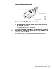
Removing and Replacing Parts 4-15 bottom of computer 5-mm screws (2) hard-disk drive door The drive is on the left side of the computer.
Removing and Replacing Parts 4-15 bottom of computer 5-mm screws (2) hard-disk drive door The drive is on the left side of the computer.
Service Manual
Page 57
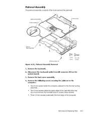
palmrest assembly 5-mm screws (2) 5-mm screw bottom case assembly 12-mm screws (3) One 5-mm screw inside the computer, adjacent to the thermal cooling assembly Two 5-mm screws inside the upper edge of the hard-disk drive bay (you must remove the hard-disk drive to access these screws) Three 12-mm screws underneath the front edge of the touch pad and the palmrest. The palmrest assembly consists of the computer Removing and Replacing Parts 4-21
palmrest assembly 5-mm screws (2) 5-mm screw bottom case assembly 12-mm screws (3) One 5-mm screw inside the computer, adjacent to the thermal cooling assembly Two 5-mm screws inside the upper edge of the hard-disk drive bay (you must remove the hard-disk drive to access these screws) Three 12-mm screws underneath the front edge of the touch pad and the palmrest. The palmrest assembly consists of the computer Removing and Replacing Parts 4-21
Service Manual
Page 78
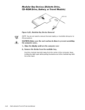
Keep holding the latch open while pulling the device out of the computer. latch lock NOTE: You do not need to remove the main battery or hard-disk drive prior to this procedure. Push the modular bay latch away from the center of the modular bay with the other hand. 4-42 Dell Latitude CP and CPi Service Manual
Keep holding the latch open while pulling the device out of the computer. latch lock NOTE: You do not need to remove the main battery or hard-disk drive prior to this procedure. Push the modular bay latch away from the center of the modular bay with the other hand. 4-42 Dell Latitude CP and CPi Service Manual
Service Manual
Page 88
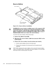
b. Remove the remnants of the foam pad from the foam pad. NOTE: When replacing the reserve battery, first connect the reserve battery cable to the system board. reserve battery reserve battery cable connector (JBAT1) To remove the reserve battery, follow these steps: a. Then position the reserve battery on the hard-disk drive bay so there is minimal slack in the cable. 4-52 Dell Latitude CP and CPi Service Manual Tear the reserve battery free from the system board assembly.
b. Remove the remnants of the foam pad from the foam pad. NOTE: When replacing the reserve battery, first connect the reserve battery cable to the system board. reserve battery reserve battery cable connector (JBAT1) To remove the reserve battery, follow these steps: a. Then position the reserve battery on the hard-disk drive bay so there is minimal slack in the cable. 4-52 Dell Latitude CP and CPi Service Manual Tear the reserve battery free from the system board assembly.
Service Manual
Page 90
..., 4-14 list of, 4-5 hard-disk drive assembly removal, 4-15 help getting, 2-6 I/O panel, 1-3 I/R board removal, 4-51 indicator panel, 1-4 initial procedures system error messages, 3-5 troubleshooting, 2-1 initialization error messages, 3-10 interrupt assignments list of, 1-6 keyboard assembly removal, 4-18 keyboard indicators, 1-5 LCD display hinge removal, 4-38 LCD inverter board removal, 4-35, 4-36 2 Dell Latitude CP and CPi Service Manual LCD panel removal, 4-31, 4-32 LEDs...
..., 4-14 list of, 4-5 hard-disk drive assembly removal, 4-15 help getting, 2-6 I/O panel, 1-3 I/R board removal, 4-51 indicator panel, 1-4 initial procedures system error messages, 3-5 troubleshooting, 2-1 initialization error messages, 3-10 interrupt assignments list of, 1-6 keyboard assembly removal, 4-18 keyboard indicators, 1-5 LCD display hinge removal, 4-38 LCD inverter board removal, 4-35, 4-36 2 Dell Latitude CP and CPi Service Manual LCD panel removal, 4-31, 4-32 LEDs...

User Guide
Page 4
... monitor to the hard-disk drive and turning off or in the upper PC Card connector. For information on the PC Card. Do not use the batteries with other computers, and do not use the special travel module in the battery bay, with the Dell Latitude CP Series. Accelerated...from other batteries (such as possible when you unpack your local waste disposal agency or environmental agency for 32-bit data transfer on removing the diskette drive and installing a different device in microphone and two stereo speakers. A modular bay that supports stand-alone and hub devices. The ...
... monitor to the hard-disk drive and turning off or in the upper PC Card connector. For information on the PC Card. Do not use the batteries with other computers, and do not use the special travel module in the battery bay, with the Dell Latitude CP Series. Accelerated...from other batteries (such as possible when you unpack your local waste disposal agency or environmental agency for 32-bit data transfer on removing the diskette drive and installing a different device in microphone and two stereo speakers. A modular bay that supports stand-alone and hub devices. The ...

User Guide
Page 11
... during takeoff and landing. Before using the computer on the computer. Dell has several carrying cases that such use is provided by hand. If the computer passes through a metal detector, first remove the hard-disk drive. If you are asked to turn on an airplane, check the ...in case you are carrying a second hard-disk drive separately, protect the drive from your government if you must pass the computer through a metal ...
... during takeoff and landing. Before using the computer on the computer. Dell has several carrying cases that such use is provided by hand. If the computer passes through a metal detector, first remove the hard-disk drive. If you are asked to turn on an airplane, check the ...in case you are carrying a second hard-disk drive separately, protect the drive from your government if you must pass the computer through a metal ...

User Guide
Page 15
... Parts: Dell™ Latitude™ CPi A-Series System User's Guide Installing a Primary Hard-Disk Drive | Installing Memory Modules Installing a Primary Hard-Disk Drive CAUTION: To prevent data loss, turn off the computer, and remove any installed batteries. 2. To install a primary hard-disk drive, perform the following steps: 1. Close the display and turn off your computer before removing the hard-disk drive. Removing a Hard-Disk Drive 3. Figure...
... Parts: Dell™ Latitude™ CPi A-Series System User's Guide Installing a Primary Hard-Disk Drive | Installing Memory Modules Installing a Primary Hard-Disk Drive CAUTION: To prevent data loss, turn off the computer, and remove any installed batteries. 2. To install a primary hard-disk drive, perform the following steps: 1. Close the display and turn off your computer before removing the hard-disk drive. Removing a Hard-Disk Drive 3. Figure...
User Guide
Page 16
... partition and logically format the hard-disk drive. Disconnect the computer and peripherals from Dell is flush with the drive to partition and logically format the drive and to create a suspend-to store data. Disconnect any attached peripherals. Remove the battery from the computer. 5. Do not drop the drive. The primary hard-disk drive may be used to -disk...
... partition and logically format the hard-disk drive. Disconnect the computer and peripherals from Dell is flush with the drive to partition and logically format the drive and to create a suspend-to store data. Disconnect any attached peripherals. Remove the battery from the computer. 5. Do not drop the drive. The primary hard-disk drive may be used to -disk...

User Guide
Page 18
Reconnect your hard-disk drive. If the total is in the slots on the bottom of the ... memory modules are operating correctly. 9. As the computer boots, it clicks into place. 6. Repeat preparatory steps 1 through 5 and removal and installation steps 1 through 8 until it detects the presence of the opening. The amount of pages 1, 2, and 4. Run the.... 7. Back to AC power and turn them on your computer and peripherals to Contents Page In one of the Dell Diagnostics to Settings, click Control Panel, and click the System icon. Use the Suspend-to-Disk utility to update ...
Reconnect your hard-disk drive. If the total is in the slots on the bottom of the ... memory modules are operating correctly. 9. As the computer boots, it clicks into place. 6. Repeat preparatory steps 1 through 5 and removal and installation steps 1 through 8 until it detects the presence of the opening. The amount of pages 1, 2, and 4. Run the.... 7. Back to AC power and turn them on your computer and peripherals to Contents Page In one of the Dell Diagnostics to Settings, click Control Panel, and click the System icon. Use the Suspend-to-Disk utility to update ...
User Guide
Page 38
...is fully seated. 7. Store the drives in the modular bay. Back to Contents Page Modular Bay: Dell™ Latitude™ CPi A-Series System User's Guide Using the Modular Bay | Installing Devices in the Modular Bay | Setting Up a Second Hard-Disk Drive Using the Modular Bay Your computer ... 6. You should hear a click when the device is docked, turn the computer over. Release the modular bay latch. You can remove the battery, diskette drive, and travel module in the modular bay, perform the following steps: 1. a. Installing Devices in the Modular Bay Table 1 explains ...
...is fully seated. 7. Store the drives in the modular bay. Back to Contents Page Modular Bay: Dell™ Latitude™ CPi A-Series System User's Guide Using the Modular Bay | Installing Devices in the Modular Bay | Setting Up a Second Hard-Disk Drive Using the Modular Bay Your computer ... 6. You should hear a click when the device is docked, turn the computer over. Release the modular bay latch. You can remove the battery, diskette drive, and travel module in the modular bay, perform the following steps: 1. a. Installing Devices in the Modular Bay Table 1 explains ...

User Guide
Page 39
.... 4. Remove the diskette drive. 3. Bay Battery Battery CD-ROM drive Diskette drive Diskette drive LS-120 drive Second hard-disk drive Travel module Device You Want to Install Diskette drive Travel module CD-ROM drive LS-120 drive Second hard-disk drive Battery Diskette drive LS-120 drive Second hard-disk drive Travel module Battery Travel module CD-ROM drive LS-120 drive Second hard-disk drive Battery CD-ROM drive Diskette drive...
.... 4. Remove the diskette drive. 3. Bay Battery Battery CD-ROM drive Diskette drive Diskette drive LS-120 drive Second hard-disk drive Travel module Device You Want to Install Diskette drive Travel module CD-ROM drive LS-120 drive Second hard-disk drive Battery Diskette drive LS-120 drive Second hard-disk drive Travel module Battery Travel module CD-ROM drive LS-120 drive Second hard-disk drive Battery CD-ROM drive Diskette drive...

User Guide
Page 40
Install the new device. 4. Setting Up a Second Hard-Disk Drive The first time you install a second hard-disk drive in the modular bay, you must format that came with the device. Turn off and undock the computer. 2. Back to Contents Page Travel module CD-ROM drive LS-120 drive Second hard-disk drive 4. Dock the computer and turn it on , if necessary. 1. For instructions, see the documentation that drive. Remove the travel module. 3. Dock the computer and turn it on .
Install the new device. 4. Setting Up a Second Hard-Disk Drive The first time you install a second hard-disk drive in the modular bay, you must format that came with the device. Turn off and undock the computer. 2. Back to Contents Page Travel module CD-ROM drive LS-120 drive Second hard-disk drive 4. Dock the computer and turn it on , if necessary. 1. For instructions, see the documentation that drive. Remove the travel module. 3. Dock the computer and turn it on .
User Guide
Page 74
... [OTP] ROM cards), and advanced technology attachment (ATA) cards that card. Also supported are generally marked with that emulate integrated drive electronics (IDE) hard-disk drives. CAUTION: Take extra precautions if you use the following PC Card combinations in the PC Card slots: A single type I or... Card connector. If card orientation is not a boot device. Back to Contents Page PC Cards: Dell™ Latitude™ CPi A-Series System User's Guide About PC Cards | Installing PC Cards | Removing PC Cards About PC Cards The computer has a slot into which end should be inserted into ,...
... [OTP] ROM cards), and advanced technology attachment (ATA) cards that card. Also supported are generally marked with that emulate integrated drive electronics (IDE) hard-disk drives. CAUTION: Take extra precautions if you use the following PC Card combinations in the PC Card slots: A single type I or... Card connector. If card orientation is not a boot device. Back to Contents Page PC Cards: Dell™ Latitude™ CPi A-Series System User's Guide About PC Cards | Installing PC Cards | Removing PC Cards About PC Cards The computer has a slot into which end should be inserted into ,...

User Guide
Page 76
Figure 2. See the PC Card operating system documentation for information. Removing a PC Card To protect the PC Card connectors, install a blank if you are not available on the hard-disk drive, prompts you to make sure the button stays flush with the card The operating system automatically detects a PC ... Panel. Configuring PC Cards The PC Card configuration utility performs the following functions: Notifies you whenever a PC Card is available on the hard-disk drive If drivers are not going to Contents Page CAUTION: The PC Card eject button can be damaged if left in the "out" position...
Figure 2. See the PC Card operating system documentation for information. Removing a PC Card To protect the PC Card connectors, install a blank if you are not available on the hard-disk drive, prompts you to make sure the button stays flush with the card The operating system automatically detects a PC ... Panel. Configuring PC Cards The PC Card configuration utility performs the following functions: Notifies you whenever a PC Card is available on the hard-disk drive If drivers are not going to Contents Page CAUTION: The PC Card eject button can be damaged if left in the "out" position...

User Guide
Page 80
...an immovable object, insert the locking device into the security cable slot on -suspend or standby mode. To prevent unauthorized removal of the hard-disk drive, insert the locking device into the security cable slot, and lock the device. Securing the Computer The administrator password ...provides access to the system, but it does not provide access to the computer and harddisk drive. Physically Securing the Computer and the Hard-Disk Drive To prevent unauthorized removal of antitheft device are usually included with the device. The same mechanism can use a security ...
...an immovable object, insert the locking device into the security cable slot on -suspend or standby mode. To prevent unauthorized removal of the hard-disk drive, insert the locking device into the security cable slot, and lock the device. Securing the Computer The administrator password ...provides access to the system, but it does not provide access to the computer and harddisk drive. Physically Securing the Computer and the Hard-Disk Drive To prevent unauthorized removal of antitheft device are usually included with the device. The same mechanism can use a security ...

User Guide
Page 96
...from RAM can activate standby mode by pressing or by pressing the power button. NOTE: Dell creates an appropriately sized suspend-to-disk (S2D) partition before you resume normal operation,...setting power conservation features. Complete the following steps in suspend-to-disk mode if you removed it was before entering standby mode. The reserve battery maintains this mode. Place the computer... enters standby mode while running and the same files will be running on the hard-disk drive and then turns off other internal devices so that were loaded before shipping the ...
...from RAM can activate standby mode by pressing or by pressing the power button. NOTE: Dell creates an appropriately sized suspend-to-disk (S2D) partition before you resume normal operation,...setting power conservation features. Complete the following steps in suspend-to-disk mode if you removed it was before entering standby mode. The reserve battery maintains this mode. Place the computer... enters standby mode while running and the same files will be running on the hard-disk drive and then turns off other internal devices so that were loaded before shipping the ...


