Service Manual
Page 4
... 1-3 Indicator Panel 1-4 Battery Indicator 3-4 Computer Orientation 4-1 Main Battery Assembly Removal 4-3 vi Figure 1-4. Figure 1-3. Figure 3-1. Figure 4-2. Hard-Disk Drive Assembly 4-15 Memory Module Cover 4-16 Memory Modules 4-17 Keyboard Assembly 4-18 Back Cover Assembly 4-20 Palmrest Assembly 4-21 Touch-Pad Interface... 4-37 LCD Display Hinge 4-38 Display-Assembly Top Cover 4-39 Bottom Case Assembly 4-40 Modular Bay Devices (Diskette Drive, CD-ROM Drive, Battery, or Travel Module 4-42 Audio Shield 4-43 Audio Board 4-44 Bottom Case Bracket 4-45 Module Latch Assemblies...
... 1-3 Indicator Panel 1-4 Battery Indicator 3-4 Computer Orientation 4-1 Main Battery Assembly Removal 4-3 vi Figure 1-4. Figure 1-3. Figure 3-1. Figure 4-2. Hard-Disk Drive Assembly 4-15 Memory Module Cover 4-16 Memory Modules 4-17 Keyboard Assembly 4-18 Back Cover Assembly 4-20 Palmrest Assembly 4-21 Touch-Pad Interface... 4-37 LCD Display Hinge 4-38 Display-Assembly Top Cover 4-39 Bottom Case Assembly 4-40 Modular Bay Devices (Diskette Drive, CD-ROM Drive, Battery, or Travel Module 4-42 Audio Shield 4-43 Audio Board 4-44 Bottom Case Bracket 4-45 Module Latch Assemblies...
Service Manual
Page 5
... 4-7. Figure 4-10. Figure 4-19. Figure 4-26. Figure 4-28. Figure 4-4. Table 4-1. Figure 4-8. Table 1-2. Figure 4-32. Screw Identification 4-3 Disconnecting an Interface Cable 4-4 Exploded View-Computer 4-14 Hard-Disk Drive Assembly Removal 4-15 Memory Module Cover Removal 4-16 Memory Module Removal 4-17 Removing the Keyboard Assembly Screws 4-18 Keyboard Assembly Removal 4-19 Back Cover Assembly...
... 4-7. Figure 4-10. Figure 4-19. Figure 4-26. Figure 4-28. Figure 4-4. Table 4-1. Figure 4-8. Table 1-2. Figure 4-32. Screw Identification 4-3 Disconnecting an Interface Cable 4-4 Exploded View-Computer 4-14 Hard-Disk Drive Assembly Removal 4-15 Memory Module Cover Removal 4-16 Memory Module Removal 4-17 Removing the Keyboard Assembly Screws 4-18 Keyboard Assembly Removal 4-19 Back Cover Assembly...
Service Manual
Page 7
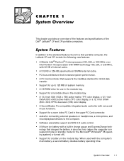
...in the modular bay. A Sound Blaster Pro-compatible integrated audio controller with the computer's main battery, a second battery doubles battery operating time. Support for a hard-disk drive in the upper PC Card connector. A 13.3-inch XGA (1024 x 768) active-matrix (TFT) color display, a 12.1-inch SVGA (800 x 600... or 300 MHz or an Intel Pentium microprocessor with MMX technology 166, 200, or 233 MHz, with 32 KB of the Dell® Latitude® CP and CPi portable computers. A 512-KB or 256-KB pipelined-burst SRAM external cache. In addition to 128 MB of system memory. Support...
...in the modular bay. A Sound Blaster Pro-compatible integrated audio controller with the computer's main battery, a second battery doubles battery operating time. Support for a hard-disk drive in the upper PC Card connector. A 13.3-inch XGA (1024 x 768) active-matrix (TFT) color display, a 12.1-inch SVGA (800 x 600... or 300 MHz or an Intel Pentium microprocessor with MMX technology 166, 200, or 233 MHz, with 32 KB of the Dell® Latitude® CP and CPi portable computers. A 512-KB or 256-KB pipelined-burst SRAM external cache. In addition to 128 MB of system memory. Support...
Service Manual
Page 9
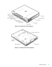
fan outlet parallel connector USB connector docking connector door docking connector serial connector monitor connector PS2 connector infrared port speaker security cable slot hard-disk drive PC Card slot modular bay latch battery bay latch memory module cover hard-disk drive System Overview 1-3
fan outlet parallel connector USB connector docking connector door docking connector serial connector monitor connector PS2 connector infrared port speaker security cable slot hard-disk drive PC Card slot modular bay latch battery bay latch memory module cover hard-disk drive System Overview 1-3
Service Manual
Page 10
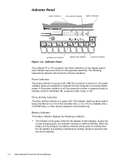
...mode (or standby mode for Windows 98), suspend-to keep the battery at full capacity. 1-4 Dell Latitude CP and CPi Service Manual The power indicator is being transferred to or from the hard-disk drive, or to indicate that the AC adapter is a green LED. If the power indicator is ...off . power indicator drive activity indicator battery indicator numbers lock indicator capitals lock indicator scroll lock indicator The Latitude CP or CPi computer has three indicators ...
...mode (or standby mode for Windows 98), suspend-to keep the battery at full capacity. 1-4 Dell Latitude CP and CPi Service Manual The power indicator is being transferred to or from the hard-disk drive, or to indicate that the AC adapter is a green LED. If the power indicator is ...off . power indicator drive activity indicator battery indicator numbers lock indicator capitals lock indicator scroll lock indicator The Latitude CP or CPi computer has three indicators ...
Service Manual
Page 12
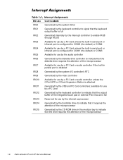
...COM2 (the default) or COM4 Available for use by a PC Card unless the built-in the modular bay to indicate that the drive requires the attention of the microprocessor Generated by the USB and PC Card controllers; available for use by a PC Card Generated by... the audio controller Generated by the diskette drive controller to indicate that the diskette drive requires the attention of the microprocessor Available for use by the internal coprocessor Generated by the hard-disk drive to indicate that it requires the attention of the microprocessor 1-6 Dell Latitude CP and CPi Service Manual
...COM2 (the default) or COM4 Available for use by a PC Card unless the built-in the modular bay to indicate that the drive requires the attention of the microprocessor Generated by the USB and PC Card controllers; available for use by a PC Card Generated by... the audio controller Generated by the diskette drive controller to indicate that the diskette drive requires the attention of the microprocessor Available for use by the internal coprocessor Generated by the hard-disk drive to indicate that it requires the attention of the microprocessor 1-6 Dell Latitude CP and CPi Service Manual
Service Manual
Page 19
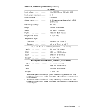
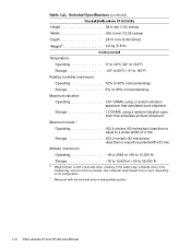
Your computer might weigh more or less, depending on its configuration. 5 Weight shown is with a hard-disk drive, a battery in the battery bay, a diskette drive in the modular bay, and one memory module. System Overview 1-13 Your computer might weigh more or less, depending on its configuration. Input voltage 90...2.5 kg (5.6 lb) Height 44.1 mm (1.74 inches) Width 306.8 mm (12.08 inches) Depth 241.0 mm (9.49 inches) Weight5 2.8 kg (6.2 lb) 4 Weight shown is with a hard-disk drive, a battery in the battery bay, a diskette drive in the modular bay, and one memory module.
Your computer might weigh more or less, depending on its configuration. 5 Weight shown is with a hard-disk drive, a battery in the battery bay, a diskette drive in the modular bay, and one memory module. System Overview 1-13 Your computer might weigh more or less, depending on its configuration. Input voltage 90...2.5 kg (5.6 lb) Height 44.1 mm (1.74 inches) Width 306.8 mm (12.08 inches) Depth 241.0 mm (9.49 inches) Weight5 2.8 kg (6.2 lb) 4 Weight shown is with a hard-disk drive, a battery in the battery bay, a diskette drive in the modular bay, and one memory module.
Service Manual
Page 20
... 10,600 m (-59 to 35,000 ft) 6 Weight shown is with the hard-disk drive in the modular bay, and one memory module. Your computer might weigh more or less, depending on its configuration. 7 Measured with a hard-disk drive, a battery in the battery bay, a diskette drive in head-parked position. 1-14 Dell Latitude CP and CPi Service Manual
... 10,600 m (-59 to 35,000 ft) 6 Weight shown is with the hard-disk drive in the modular bay, and one memory module. Your computer might weigh more or less, depending on its configuration. 7 Measured with a hard-disk drive, a battery in the battery bay, a diskette drive in head-parked position. 1-14 Dell Latitude CP and CPi Service Manual
Service Manual
Page 25
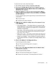
... (Num Lock), the capitals lock (Caps Lock), and the Scroll Lock indicators flash simultaneously during the boot routine, troubleshoot the diskette-drive or hard-disk drive subsystem, as appropriate. These messages can indicate problems or provide status information. If the indicator fails to light during the boot routine,... the boot routine, follow these steps: Do these indicators light up in response to data being transferred to or from the drives. Drive access indicator - Error codes - Yes. See "Running the Dell Diagnostics" in Chapter 3. Proceed to step 6. See "Running the...
... (Num Lock), the capitals lock (Caps Lock), and the Scroll Lock indicators flash simultaneously during the boot routine, troubleshoot the diskette-drive or hard-disk drive subsystem, as appropriate. These messages can indicate problems or provide status information. If the indicator fails to light during the boot routine,... the boot routine, follow these steps: Do these indicators light up in response to data being transferred to or from the drives. Drive access indicator - Error codes - Yes. See "Running the Dell Diagnostics" in Chapter 3. Proceed to step 6. See "Running the...
Service Manual
Page 31
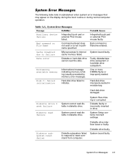
... or external PS/2 mouse failed. System Setup contains incorrect settings. Hard-disk drive failed to reset command from computer. Bad command or filename entered. System board faulty. Hard-disk drive damaged. System files missing or corrupted. Diskette subsystem failed to respond... operation. System Error Messages 3-5 Diskette or hard-disk drive cannot read diskette in diskette drive. System cannot read the data. Diskette drive faulty. Diskette drive interface loose or faulty. The following table lists (in drive. Informational message indicating memory is not in ...
... or external PS/2 mouse failed. System Setup contains incorrect settings. Hard-disk drive failed to reset command from computer. Bad command or filename entered. System board faulty. Hard-disk drive damaged. System files missing or corrupted. Diskette subsystem failed to respond... operation. System Error Messages 3-5 Diskette or hard-disk drive cannot read diskette in diskette drive. System cannot read the data. Diskette drive faulty. Diskette drive interface loose or faulty. The following table lists (in drive. Informational message indicating memory is not in ...

Service Manual
Page 32
.... PC Card software faulty or incorrectly installed. Hard-disk drive faulty. 3-6 Dell Latitude CP and CPi Service Manual Diskette writeprotected Drive not ready Error reading PCMCIA card Extended memory size has changed Gate A20 failure General failure Hard-disk drive configuration error Hard-disk drive controller failure 0 Hard-disk drive controller failure 1 Hard-disk drive failure Hard-disk drive read failure Diskette is writeprotected; Diskette writeprotected...
.... PC Card software faulty or incorrectly installed. Hard-disk drive faulty. 3-6 Dell Latitude CP and CPi Service Manual Diskette writeprotected Drive not ready Error reading PCMCIA card Extended memory size has changed Gate A20 failure General failure Hard-disk drive configuration error Hard-disk drive controller failure 0 Hard-disk drive controller failure 1 Hard-disk drive failure Hard-disk drive read failure Diskette is writeprotected; Diskette writeprotected...

Service Manual
Page 34
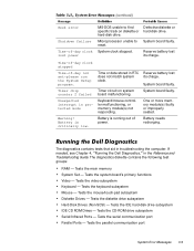
...failed. No boot sector on system board malfunctioning. Timer on harddisk drive. No operating system files on diskette or hard-disk drive. 3-8 Dell Latitude CP and CPi Service Manual Unable to locate a sector on diskette or hard-disk drive. Memory data line failure at address, read value expecting value Memory... expecting value Memory write/read failure at address, read value expecting value No boot device available No boot sector on hard-disk drive No timer tick interrupt Non-system disk or disk error Not a boot diskette Optional ROM bad checksum Sector not found...
...failed. No boot sector on system board malfunctioning. Timer on harddisk drive. No operating system files on diskette or hard-disk drive. 3-8 Dell Latitude CP and CPi Service Manual Unable to locate a sector on diskette or hard-disk drive. Memory data line failure at address, read value expecting value Memory... expecting value Memory write/read failure at address, read value expecting value No boot device available No boot sector on hard-disk drive No timer tick interrupt Non-system disk or disk error Not a boot diskette Optional ROM bad checksum Sector not found...
Service Manual
Page 35
...interrupt in the Reference and Troubleshooting Guide. System board faulty. Battery needs recharging. If needed, see Chapter 4, "Running the Dell Diagnostics," in protected mode Warning! Tests the keyboard subsystem Mouse - Seek error Shutdown failure Time-of-day clock lost its charge... aid in RTC does not match system clock. Tests the mouse/touch-pad subsystem Diskette Drives - Tests the video subsystem Keyboard - Timer circuit on diskette or hard-disk drive. Battery is critically low. Reserve battery lost its charge. The diagnostics diskette contains the ...
...interrupt in the Reference and Troubleshooting Guide. System board faulty. Battery needs recharging. If needed, see Chapter 4, "Running the Dell Diagnostics," in protected mode Warning! Tests the keyboard subsystem Mouse - Seek error Shutdown failure Time-of-day clock lost its charge... aid in RTC does not match system clock. Tests the mouse/touch-pad subsystem Diskette Drives - Tests the video subsystem Keyboard - Timer circuit on diskette or hard-disk drive. Battery is critically low. Reserve battery lost its charge. The diagnostics diskette contains the ...
Service Manual
Page 43
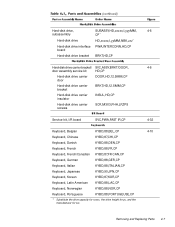
Hard-disk drive, subassembly Hard-disk drive Hard-disk drive interface board Hard-disk drive bracket SUBASSY,HD,xxxxx,I,yyyMM, CP* HD,xxxxx,I,yyMM,NBK,zzz* PWA,INTERCONN,HD,CP BRKT,HD,CP Hard-disk drive carrier bracket/ SVC,ASSY,BRKT/DOOR, door assembly service kit HD,CP Hard-disk drive carrier door DOOR,HD,12.5MM,CP Hard-disk drive carrier bracket BRKT,HD...
Hard-disk drive, subassembly Hard-disk drive Hard-disk drive interface board Hard-disk drive bracket SUBASSY,HD,xxxxx,I,yyyMM, CP* HD,xxxxx,I,yyMM,NBK,zzz* PWA,INTERCONN,HD,CP BRKT,HD,CP Hard-disk drive carrier bracket/ SVC,ASSY,BRKT/DOOR, door assembly service kit HD,CP Hard-disk drive carrier door DOOR,HD,12.5MM,CP Hard-disk drive carrier bracket BRKT,HD...

Service Manual
Page 48
...ZPS LCD hinge LCD inverter board LCD bezel and latch, 12.1-inch display Keyboard Thermal cooling assembly Touch-pad Palmrest, front edge Palmrest, hard-disk drive area I/R board Upper EMI shield, 1st PC/Video board Back cover Audio board Upper EMI shield, 2nd Bottom-case bracket Exhaust fan ... assembly with system board and processor module ASSY,PRM/PWA,ENGINE, CPxxx* * Substitute the drive capacity for xxxxx, the drive height for yy, and the manufacturer for zzz. 4-18, 4-19 4-16 4-21 4-17 4-9 4-30 4-13 4-12 4-12 4-32 4-11 4-26 4-27 4-31 4-30 4-12 Dell Latitude CP and CPi Service Manual
...ZPS LCD hinge LCD inverter board LCD bezel and latch, 12.1-inch display Keyboard Thermal cooling assembly Touch-pad Palmrest, front edge Palmrest, hard-disk drive area I/R board Upper EMI shield, 1st PC/Video board Back cover Audio board Upper EMI shield, 2nd Bottom-case bracket Exhaust fan ... assembly with system board and processor module ASSY,PRM/PWA,ENGINE, CPxxx* * Substitute the drive capacity for xxxxx, the drive height for yy, and the manufacturer for zzz. 4-18, 4-19 4-16 4-21 4-17 4-9 4-30 4-13 4-12 4-12 4-32 4-11 4-26 4-27 4-31 4-30 4-12 Dell Latitude CP and CPi Service Manual
Service Manual
Page 51
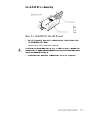
Removing and Replacing Parts 4-15 bottom of computer 5-mm screws (2) hard-disk drive door The drive is on the left side of the computer.
Removing and Replacing Parts 4-15 bottom of computer 5-mm screws (2) hard-disk drive door The drive is on the left side of the computer.
Service Manual
Page 57
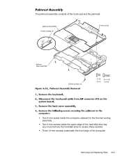
The palmrest assembly consists of the computer Removing and Replacing Parts 4-21 palmrest assembly 5-mm screws (2) 5-mm screw bottom case assembly 12-mm screws (3) One 5-mm screw inside the computer, adjacent to the thermal cooling assembly Two 5-mm screws inside the upper edge of the hard-disk drive bay (you must remove the hard-disk drive to access these screws) Three 12-mm screws underneath the front edge of the touch pad and the palmrest.
The palmrest assembly consists of the computer Removing and Replacing Parts 4-21 palmrest assembly 5-mm screws (2) 5-mm screw bottom case assembly 12-mm screws (3) One 5-mm screw inside the computer, adjacent to the thermal cooling assembly Two 5-mm screws inside the upper edge of the hard-disk drive bay (you must remove the hard-disk drive to access these screws) Three 12-mm screws underneath the front edge of the touch pad and the palmrest.
User Guide
Page 49
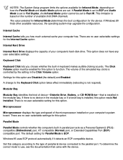
... Click Keyboard Click lets you how much external cache your computer has. The volume of the microprocessor installed on your computer's hard-disk drive. A change to Fast IR. Microprocessor Microprocessor displays the type and speed of the simulated key clicks is installed in the ...modular bay. Parallel Mode Parallel Mode controls whether the computer's built-in the Click Volume option. Internal Hard Drive Internal Hard Drive displays the capacity of peripheral device connected to the parallel port. Settings for this category according to the type of your ...
... Click Keyboard Click lets you how much external cache your computer has. The volume of the microprocessor installed on your computer's hard-disk drive. A change to Fast IR. Microprocessor Microprocessor displays the type and speed of the simulated key clicks is installed in the ...modular bay. Parallel Mode Parallel Mode controls whether the computer's built-in the Click Volume option. Internal Hard Drive Internal Hard Drive displays the capacity of peripheral device connected to the parallel port. Settings for this category according to the type of your ...
User Guide
Page 94
... all the options set to Off. Table 1. Key Combinations to Activate/Deactivate Features Feature Turn off display Turn off the hard-disk drive. Using Key Combinations Table 1 identifies the power management key combinations. NOTE: To use key combinations on the built-in or... or set at their minimum or maximum values. To deactivate, press the power button. Back to Contents Page Power Management Settings: Dell™ Latitude™ CPi A-Series System User's Guide Experimenting With Power Conservation | Using Key Combinations | Closing the Display | Suspend Mode | Suspend-to-...
... all the options set to Off. Table 1. Key Combinations to Activate/Deactivate Features Feature Turn off display Turn off the hard-disk drive. Using Key Combinations Table 1 identifies the power management key combinations. NOTE: To use key combinations on the built-in or... or set at their minimum or maximum values. To deactivate, press the power button. Back to Contents Page Power Management Settings: Dell™ Latitude™ CPi A-Series System User's Guide Experimenting With Power Conservation | Using Key Combinations | Closing the Display | Suspend Mode | Suspend-to-...

User Guide
Page 170
... any user-selectable settings. If Windows 95 finds other available resources, the operating system may upgrade the configuration. Internal Hard Drive Internal Hard Drive displays the capacity of device-Diskette Drive, Battery, or CD-ROM Drive-that came with the device. Microprocessor Microprocessor displays the type and speed of the microprocessor installed on the number of...
... any user-selectable settings. If Windows 95 finds other available resources, the operating system may upgrade the configuration. Internal Hard Drive Internal Hard Drive displays the capacity of device-Diskette Drive, Battery, or CD-ROM Drive-that came with the device. Microprocessor Microprocessor displays the type and speed of the microprocessor installed on the number of...


