
Owners Manual
Page 3
... card tray...10 Replacing SIM card...10 Base cover...10 Removing base cover...10 Installing base cover...12 Battery...12 Lithium-ion battery precautions...12 Removing battery...12 Installing battery...13 PCIe Solid State Drive (SSD)...13 Removing PCIe SSD...13 Installing PCIe SSD...14 Speaker...14 Removing... speaker module...14 Installing speaker module...16 Coin-cell battery...16 Removing the coin cell battery...16 Installing coin cell battery...17 WWAN card...17 Removing WWAN card...17 Installing WWAN card...18 WLAN card...18 Removing WLAN ...
... card tray...10 Replacing SIM card...10 Base cover...10 Removing base cover...10 Installing base cover...12 Battery...12 Lithium-ion battery precautions...12 Removing battery...12 Installing battery...13 PCIe Solid State Drive (SSD)...13 Removing PCIe SSD...13 Installing PCIe SSD...14 Speaker...14 Removing... speaker module...14 Installing speaker module...16 Coin-cell battery...16 Removing the coin cell battery...16 Installing coin cell battery...17 WWAN card...17 Removing WWAN card...17 Installing WWAN card...18 WLAN card...18 Removing WLAN ...
Owners Manual
Page 4
... 3 System specifications...44 Supported operating systems...44 Processor specifications...44 System specifications...45 Memory specifications...45 Storage specifications...45 Video specifications...45 Audio specifications...45 Battery specifications...46 AC adapter specifications...46 Docking options...47 Port and connector specifications...47 Communication specifications...47 Camera specifications...48 Touchpad specifications...48 Display specifications...
... 3 System specifications...44 Supported operating systems...44 Processor specifications...44 System specifications...45 Memory specifications...45 Storage specifications...45 Video specifications...45 Audio specifications...45 Battery specifications...46 AC adapter specifications...46 Docking options...47 Port and connector specifications...47 Communication specifications...47 Camera specifications...48 Touchpad specifications...48 Display specifications...

Owners Manual
Page 7
... by its pins. Damage due to the power source. if you pull connectors apart, keep them evenly aligned to the computer, use batteries designed for other Dell computers. 1. After working inside your computer. 5. Press and hold the power button for this type of cable, press in on the...devices, cards, and cables before opening the computer cover or panels. Hold a component such as an ExpressCard. 2. Do not use only the battery designed for few seconds, to your computer. After you touch the computer to ensure your computer, read the safety information that is not covered ...
... by its pins. Damage due to the power source. if you pull connectors apart, keep them evenly aligned to the computer, use batteries designed for other Dell computers. 1. After working inside your computer. 5. Press and hold the power button for this type of cable, press in on the...devices, cards, and cables before opening the computer cover or panels. Hold a component such as an ExpressCard. 2. Do not use only the battery designed for few seconds, to your computer. After you touch the computer to ensure your computer, read the safety information that is not covered ...
Owners Manual
Page 9
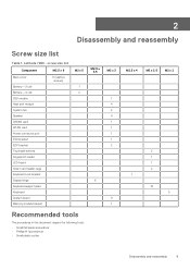
screw size list Component M2.5 x 6 Back cover Battery-3-cell Battery-4-cell SSD module Heat sink module System fan Speaker WWAN card WLAN card Power connector port ESD bracket EDP bracket Touchpad buttons Fingerprint reader LED ... require the following tools: • Small flat blade screwdriver • Phillips # 1 screwdriver • Small plastic scribe M2.5 x 3.5 6 M2 x 3 1 4 2 4 1 1 1 1 2 9 1 M2.5 x 4 M2 x 2.5 M2 x 2 2 1 1 2 1 19 5 Disassembly and reassembly 9 Latitude 7280 - 2 Disassembly and reassembly Screw size list Table 1.
screw size list Component M2.5 x 6 Back cover Battery-3-cell Battery-4-cell SSD module Heat sink module System fan Speaker WWAN card WLAN card Power connector port ESD bracket EDP bracket Touchpad buttons Fingerprint reader LED ... require the following tools: • Small flat blade screwdriver • Phillips # 1 screwdriver • Small plastic scribe M2.5 x 3.5 6 M2 x 3 1 4 2 4 1 1 1 1 2 9 1 M2.5 x 4 M2 x 2.5 M2 x 2 2 1 1 2 1 19 5 Disassembly and reassembly 9 Latitude 7280 - 2 Disassembly and reassembly Screw size list Table 1.

Owners Manual
Page 12
...the base cover to the computer [2]. NOTE: Exercise caution when tightening the screws. In such an instance, contact Dell technical support for assistance and further instructions. • If the battery gets stuck inside your computer as a result of swelling, do not try to match the head of the ... edges of the screw to the slots on the system board [1]. Follow the procedure in Before working inside your computer. Lift the battery from www.dell.com or authorized Dell partners and resellers. Align the base cover tabs to avoid a possible stripped screw head. 4. Disconnect the...
...the base cover to the computer [2]. NOTE: Exercise caution when tightening the screws. In such an instance, contact Dell technical support for assistance and further instructions. • If the battery gets stuck inside your computer as a result of swelling, do not try to match the head of the ... edges of the screw to the slots on the system board [1]. Follow the procedure in Before working inside your computer. Lift the battery from www.dell.com or authorized Dell partners and resellers. Align the base cover tabs to avoid a possible stripped screw head. 4. Disconnect the...

Owners Manual
Page 13
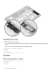
... the procedure in After working inside your computer. 2. Remove the PCIe SSD from the connector on the computer. 2. Insert the battery into the slot on the system board [3]. Follow the procedure in Before working inside your computer. Remove the : a. c. Loosen the M2 x3... the base cover 5. Tighten the M2.0 x 5.0 screws to secure the battery to the connector on the system board. Disassembly and reassembly 13 Route the battery cable through the routing clip and connect the battery cable to the computer. NOTE: Route the battery cable, if the cable at the base of the...
... the procedure in After working inside your computer. 2. Remove the PCIe SSD from the connector on the computer. 2. Insert the battery into the slot on the system board [3]. Follow the procedure in Before working inside your computer. Remove the : a. c. Loosen the M2 x3... the base cover 5. Tighten the M2.0 x 5.0 screws to secure the battery to the connector on the system board. Disassembly and reassembly 13 Route the battery cable through the routing clip and connect the battery cable to the computer. NOTE: Route the battery cable, if the cable at the base of the...
Owners Manual
Page 14
NOTE: Ensure to secure it the SSD bracket. 4. battery b. Speaker Removing speaker module 1. Follow the procedure in After working inside your computer. base cover b. Tighten the M2 x 3 screws to install the bracket is the ... the PCIe SSD card into the connector. 2. Install the SSD bracket over the PCIe SSD card. Follow the procedure in Before working iinside your computer. 2. battery 14 Disassembly and reassembly NOTE: When installing the SSD bracket, ensure that the tab on the bracket is shipped with the tab on the palm...
NOTE: Ensure to secure it the SSD bracket. 4. battery b. Speaker Removing speaker module 1. Follow the procedure in After working inside your computer. base cover b. Tighten the M2 x 3 screws to install the bracket is the ... the PCIe SSD card into the connector. 2. Install the SSD bracket over the PCIe SSD card. Follow the procedure in Before working iinside your computer. 2. battery 14 Disassembly and reassembly NOTE: When installing the SSD bracket, ensure that the tab on the bracket is shipped with the tab on the palm...
Owners Manual
Page 16
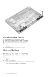
... Connect the speaker cable to the computer. 3. Follow the procedure in Before working inside your computer. Coin-cell battery Removing the coin cell battery 1. base cover b. Disconnect the coin cell battery cable from the adhesive [2]. 16 Disassembly and reassembly Place the speaker module into the slots on the system board.... 5. Tighten the M2.0x3.0 screws to secure the speaker to the connector on the computer. 2. battery b. Lift the coin cell battery to release it from the connector on the computer. 4. To remove the coin cell...
... Connect the speaker cable to the computer. 3. Follow the procedure in Before working inside your computer. Coin-cell battery Removing the coin cell battery 1. base cover b. Disconnect the coin cell battery cable from the adhesive [2]. 16 Disassembly and reassembly Place the speaker module into the slots on the system board.... 5. Tighten the M2.0x3.0 screws to secure the speaker to the connector on the computer. 2. battery b. Lift the coin cell battery to release it from the connector on the computer. 4. To remove the coin cell...
Owners Manual
Page 17
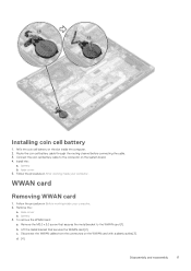
... cover 5. Remove the M2.0 x 3.0 screw that secures the WWAN card [2]. Route the coin cell battery cable through the routing channel before connecting the cable. 3. Follow the procedure in After working inside the computer. 2. Disassembly and ...reassembly 17 battery b. Remove the : a. WWAN card Removing WWAN card 1. c. Installing coin cell battery 1. Install the : a. Follow the procedure in Before working inside your computer. 2. Affix the coin cell battery on the WWAN card with a plastic scribe.[3]. To remove...
... cover 5. Remove the M2.0 x 3.0 screw that secures the WWAN card [2]. Route the coin cell battery cable through the routing channel before connecting the cable. 3. Follow the procedure in After working inside the computer. 2. Disassembly and ...reassembly 17 battery b. Remove the : a. WWAN card Removing WWAN card 1. c. Installing coin cell battery 1. Install the : a. Follow the procedure in Before working inside your computer. 2. Affix the coin cell battery on the WWAN card with a plastic scribe.[3]. To remove...

Owners Manual
Page 18
battery b. base cover 5. battery 3. Lift the metal bracket [2]. Disconnect the WLAN cables from the connectors on the WWAN card. Install the : a. NOTE: The IMEI number can also be found ...
battery b. base cover 5. battery 3. Lift the metal bracket [2]. Disconnect the WLAN cables from the connectors on the WWAN card. Install the : a. NOTE: The IMEI number can also be found ...

Owners Manual
Page 19
...Connect the WLAN cables to the connectors on the system board. 2. base cover 5. Follow the procedure in Before working inside your computer. Remove the : a. battery 3. To remove the memory module: a. b. NOTE: Ensure NOT to pull the WLAN card more than 35°, to avoid damage to the computer. 4....the module snaps-out [1]. Install the .: a. Disassembly and reassembly 19 Remove the memory module from the computer [4]. Installing WLAN card 1. battery b. base cover b. d. Remove the WLAN card from the connector on the system board [2]. Memory module Removing memory module 1.
...Connect the WLAN cables to the connectors on the system board. 2. base cover 5. Follow the procedure in Before working inside your computer. Remove the : a. battery 3. To remove the memory module: a. b. NOTE: Ensure NOT to pull the WLAN card more than 35°, to avoid damage to the computer. 4....the module snaps-out [1]. Install the .: a. Disassembly and reassembly 19 Remove the memory module from the computer [4]. Installing WLAN card 1. battery b. base cover b. d. Remove the WLAN card from the connector on the system board [2]. Memory module Removing memory module 1.
Owners Manual
Page 20
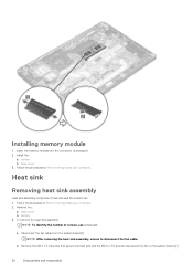
... [1]. Remove the : a. NOTE: After removing the heat sink assembly, ensure to the system board [2]. 20 Disassembly and reassembly battery 3. Heat sink Removing heat sink assembly Heat sink assembly comprises of screws, see screw list. Insert the memory module into the... working inside your computer. 2. To remove the heat sink assembly: NOTE: To identify the number of heat sink and the system fan. 1. b. battery b. Installing memory module 1. Install the : a. Follow the procedures in . 2. Follow the procedure in Before working inside your computer. base cover b....
... [1]. Remove the : a. NOTE: After removing the heat sink assembly, ensure to the system board [2]. 20 Disassembly and reassembly battery 3. Heat sink Removing heat sink assembly Heat sink assembly comprises of screws, see screw list. Insert the memory module into the... working inside your computer. 2. To remove the heat sink assembly: NOTE: To identify the number of heat sink and the system fan. 1. b. battery b. Installing memory module 1. Install the : a. Follow the procedures in . 2. Follow the procedure in Before working inside your computer. base cover b....

Owners Manual
Page 21
...of the callout numbers [1, 2, 3, 4] as indicated on the heat sink. 3. base cover 6. Power connector port Removing power connector port 1. battery 3. To remove the power connector port: a. NOTE: Remove the screws in the order of the callout numbers [1, 2, 3, 4] as indicated on... board 4. Install the : a. base cover b. Disconnect the power connector port cable from the system board [3]. Disassembly and reassembly 21 battery b. Follow the procedure in After working inside your computer. 2. Follow the procedure in Before working inside your computer. c. Tighten the M2...
...of the callout numbers [1, 2, 3, 4] as indicated on the heat sink. 3. base cover 6. Power connector port Removing power connector port 1. battery 3. To remove the power connector port: a. NOTE: Remove the screws in the order of the callout numbers [1, 2, 3, 4] as indicated on... board 4. Install the : a. base cover b. Disconnect the power connector port cable from the system board [3]. Disassembly and reassembly 21 battery b. Follow the procedure in After working inside your computer. 2. Follow the procedure in Before working inside your computer. c. Tighten the M2...

Owners Manual
Page 22
... port from the connector. Connect the power connector port cable to the connector on the computer. 2. Installing power connector port 1. LED board Removing LED board 1. battery b. Follow the procedure in After working inside your computer. 2. NOTE: Ensure to the computer. 4. NOTE: Use a plastic scribe to release the metal bracket on the...
... port from the connector. Connect the power connector port cable to the connector on the computer. 2. Installing power connector port 1. LED board Removing LED board 1. battery b. Follow the procedure in After working inside your computer. 2. NOTE: Ensure to the computer. 4. NOTE: Use a plastic scribe to release the metal bracket on the...
Owners Manual
Page 23
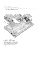
.... 2. Disassembly and reassembly 23 a. Remove the M2.0 x 2.5 screw that secures the LED board to secure the LED board. 3. Tighten the M2.0 x 2.5 screw to the computer [3] d. battery 3. Follow the procedure in breaking the cable connector. Installing LED board 1. To remove the LED board: a. Instead, use a scribe to the system board. 5. Route the...
.... 2. Disassembly and reassembly 23 a. Remove the M2.0 x 2.5 screw that secures the LED board to secure the LED board. 3. Tighten the M2.0 x 2.5 screw to the computer [3] d. battery 3. Follow the procedure in breaking the cable connector. Installing LED board 1. To remove the LED board: a. Instead, use a scribe to the system board. 5. Route the...
Owners Manual
Page 24
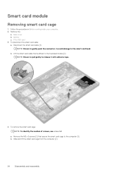
... from the computer [2]. 24 Disassembly and reassembly Remove the: a. NOTE: Ensure to gently push the connector, to avoid damage to release it with adhesive tape. 4. b. battery c. Smart card module Removing smart card cage 1. To remove the smart card cage: NOTE: To identify the number of screws, see screw list a.
... from the computer [2]. 24 Disassembly and reassembly Remove the: a. NOTE: Ensure to gently push the connector, to avoid damage to release it with adhesive tape. 4. b. battery c. Smart card module Removing smart card cage 1. To remove the smart card cage: NOTE: To identify the number of screws, see screw list a.

Owners Manual
Page 25
... to align with the tabs on the computer . 4. base cover 5. Touchpad Removing touchpad buttons board 1. To disconnect the smart card cable: a. Disassembly and reassembly 25 battery c. battery c. Disconnect the smart card cable [1]. Slide the smart card cage into the slot to the connector on the computer. 2. Install the: a. Tighten the M2 x 3 screws...
... to align with the tabs on the computer . 4. base cover 5. Touchpad Removing touchpad buttons board 1. To disconnect the smart card cable: a. Disassembly and reassembly 25 battery c. battery c. Disconnect the smart card cable [1]. Slide the smart card cage into the slot to the connector on the computer. 2. Install the: a. Tighten the M2 x 3 screws...

Owners Manual
Page 27
... 27 speaker b. Follow the procedure in Before working inside your computer. Affix the smart card cable and connect it to the connector on the computer 5. battery c. battery c. Connect the touchpad buttons board cable to the connector on the touchpad board. 4. base cover b. Installing touchpad buttons board 1. Tighten the M2.0 x 2.5screws to secure...
... 27 speaker b. Follow the procedure in Before working inside your computer. Affix the smart card cable and connect it to the connector on the computer 5. battery c. battery c. Connect the touchpad buttons board cable to the connector on the touchpad board. 4. base cover b. Installing touchpad buttons board 1. Tighten the M2.0 x 2.5screws to secure...

Owners Manual
Page 29
...table and position it closer to align it clicks onto the display assembly. Affix the tapes to the display panel. 3. WWAN card c. battery d. Place the display bezel on the eDP cable and tighten the M2.0 x 5.0 screws. 7. base cover 4. NOTE: Adhesive is applicable ...only for non-touch systems. 1. battery e. Install the eDP metal bracket on the display assembly. 2. Follow the procedure in After working inside your computer. Disassembly and reassembly 29 ...
...table and position it closer to align it clicks onto the display assembly. Affix the tapes to the display panel. 3. WWAN card c. battery d. Place the display bezel on the eDP cable and tighten the M2.0 x 5.0 screws. 7. base cover 4. NOTE: Adhesive is applicable ...only for non-touch systems. 1. battery e. Install the eDP metal bracket on the display assembly. 2. Follow the procedure in After working inside your computer. Disassembly and reassembly 29 ...

Owners Manual
Page 30
WLAN card d. WWAN card e. Installing the display hinge cap 1. WWAN card d. battery e. WWAN card e. battery c. Place the display hinge cap on the slot and slide it back to release and remove the display hinge cap from the ...base cover 3. Follow the procedure in Before working inside your computer. 2. WLAN card d. Follow the procedure in After working inside your computer. Install the: a. battery c. Removing the display hinge cap 1. Follow the procedure in Before working inside your computer. 2. Remove the following components: a. Slide hinge cap from left to ...
WLAN card d. WWAN card e. Installing the display hinge cap 1. WWAN card d. battery e. WWAN card e. battery c. Place the display hinge cap on the slot and slide it back to release and remove the display hinge cap from the ...base cover 3. Follow the procedure in Before working inside your computer. 2. WLAN card d. Follow the procedure in After working inside your computer. Install the: a. battery c. Removing the display hinge cap 1. Follow the procedure in Before working inside your computer. 2. Remove the following components: a. Slide hinge cap from left to ...


