

Dell Latitude 10 - ST2e Owner's Manual
Page 3
... and Installing Components 9 Recommended Tools...9 Internal View...9 Removing the Base Cover...10 Installing the Base Cover...10 Removing the Battery...10 Installing the Battery...11 Removing the Front Camera...11 Installing the Front Camera...12 Removing the Speakers...12 Installing the Speakers...14 Removing the ...Installing the System Board...16 Removing the Rear Camera...17 Installing the Rear Camera...17 Removing the Coin-Cell Battery...18 Installing the Coin-Cell Battery...18 Removing the Volume-Button Board...18 Installing the Volume-Button Board...19 3 System Setup...21 Entering System ...
... and Installing Components 9 Recommended Tools...9 Internal View...9 Removing the Base Cover...10 Installing the Base Cover...10 Removing the Battery...10 Installing the Battery...11 Removing the Front Camera...11 Installing the Front Camera...12 Removing the Speakers...12 Installing the Speakers...14 Removing the ...Installing the System Board...16 Removing the Rear Camera...17 Installing the Rear Camera...17 Removing the Coin-Cell Battery...18 Installing the Coin-Cell Battery...18 Removing the Volume-Button Board...18 Installing the Volume-Button Board...19 3 System Setup...21 Entering System ...

Dell Latitude 10 - ST2e Owner's Manual
Page 6
... an unpainted metal surface, such as an ExpressCard. 2. Ensure that the computer and all attached devices to the computer, use batteries designed for other Dell computers. 1. Connect any telephone or network cables to upper-right corner of the computer. Turn on your computer. and then ...edge of the screen, opening the display. Windows 8: * Using a touch-enabled device: Swipe in from the slots. Shut down . Replace the battery. 4. CAUTION: To connect a network cable, first plug the cable into the network device and then plug it into the computer. 3. Connect any...
... an unpainted metal surface, such as an ExpressCard. 2. Ensure that the computer and all attached devices to the computer, use batteries designed for other Dell computers. 1. Connect any telephone or network cables to upper-right corner of the computer. Turn on your computer. and then ...edge of the screen, opening the display. Windows 8: * Using a touch-enabled device: Swipe in from the slots. Shut down . Replace the battery. 4. CAUTION: To connect a network cable, first plug the cable into the network device and then plug it into the computer. 3. Connect any...

Dell Latitude 10 - ST2e Owner's Manual
Page 9
system board 2. rear camera 4. battery 9 2 Removing and Installing Components This section provides detailed information on how to remove or install the components from your computer. Internal View 1. front camera 3. Recommended Tools The procedures in this document may require the following tools: • Small flat-blade screwdriver • #0 Phillips screwdriver • #1 Phillips screwdriver • Small plastic scribe Internal View Figure 1.
system board 2. rear camera 4. battery 9 2 Removing and Installing Components This section provides detailed information on how to remove or install the components from your computer. Internal View 1. front camera 3. Recommended Tools The procedures in this document may require the following tools: • Small flat-blade screwdriver • #0 Phillips screwdriver • #1 Phillips screwdriver • Small plastic scribe Internal View Figure 1.
Dell Latitude 10 - ST2e Owner's Manual
Page 10
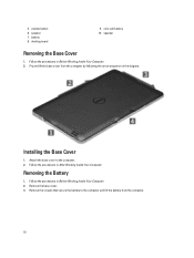
... Removing the Base Cover 1. Attach the base cover to the computer and lift the battery from the computer by following the arrow sequence in Before Working Inside Your Computer. 2. Removing the Battery 1. speaker 7. coin-cell battery 10. Follow the procedures in After Working Inside Your Computer. Installing the Base Cover 1. Follow the procedures...
... Removing the Base Cover 1. Attach the base cover to the computer and lift the battery from the computer by following the arrow sequence in Before Working Inside Your Computer. 2. Removing the Battery 1. speaker 7. coin-cell battery 10. Follow the procedures in After Working Inside Your Computer. Installing the Base Cover 1. Follow the procedures...

Dell Latitude 10 - ST2e Owner's Manual
Page 11
Remove the: a) base cover b) battery 3. Follow the procedures in After Working Inside Your Computer. Remove the camera module from the computer. 11 Remove the screw that secures the camera module to the computer. 2. Follow the procedures in Before Working Inside Your Computer. 2. Removing the Front Camera 1. Lift up the connector latch and disconnect the camera cable. Installing the Battery 1. Tighten the screws to secure the battery to the computer. Install the base cover. 3.
Remove the: a) base cover b) battery 3. Follow the procedures in After Working Inside Your Computer. Remove the camera module from the computer. 11 Remove the screw that secures the camera module to the computer. 2. Follow the procedures in Before Working Inside Your Computer. 2. Removing the Front Camera 1. Lift up the connector latch and disconnect the camera cable. Installing the Battery 1. Tighten the screws to secure the battery to the computer. Install the base cover. 3.

Dell Latitude 10 - ST2e Owner's Manual
Page 12
Follow the procedures in Before Working Inside Your Computer. 2. Installing the Front Camera 1. Install the: a) battery b) base cover 5. Lift up the coin-cell battery from its slot on the computer. 2. Disconnect the speaker connector from below the speaker. Remove the screws that secure the speakers to the connector. 4. Place ... Your Computer. Connect the camera cable to the computer. 12 Tighten the screw to secure the camera module to the computer. 3. Remove the : a) base cover b) battery 3.
Follow the procedures in Before Working Inside Your Computer. 2. Installing the Front Camera 1. Install the: a) battery b) base cover 5. Lift up the coin-cell battery from its slot on the computer. 2. Disconnect the speaker connector from below the speaker. Remove the screws that secure the speakers to the connector. 4. Place ... Your Computer. Connect the camera cable to the computer. 12 Tighten the screw to secure the camera module to the computer. 3. Remove the : a) base cover b) battery 3.

Dell Latitude 10 - ST2e Owner's Manual
Page 14
... d) front camera 3. Lift up the connector latch and disconnect the docking-board power cable from the connector. 14 Place the coin-cell battery in their slot. 2. Install the : a) battery b) base cover 7. Follow the procedures in After Working Inside Your Computer. Connect the speaker connector cable to the chassis. 4. Follow the procedures in...
... d) front camera 3. Lift up the connector latch and disconnect the docking-board power cable from the connector. 14 Place the coin-cell battery in their slot. 2. Install the : a) battery b) base cover 7. Follow the procedures in After Working Inside Your Computer. Connect the speaker connector cable to the chassis. 4. Follow the procedures in...

Dell Latitude 10 - ST2e Owner's Manual
Page 15
Installing the Docking Board 1. Tighten the screws to secure the docking board to the docking board and place the docking board in its slot in After Working Inside Your Computer. 15 Install the: a) front camera b) speaker c) battery d) base cover 5. Connect the home-button board cable to the computer. 3. Connect the docking-board power cable to the computer. 5. Remove the docking board from the computer and disconnect the home-button board cable. Remove the screws that secure the docking board to the connector. 4. 4. Follow the procedures in the computer. 2.
Installing the Docking Board 1. Tighten the screws to secure the docking board to the docking board and place the docking board in its slot in After Working Inside Your Computer. 15 Install the: a) front camera b) speaker c) battery d) base cover 5. Connect the home-button board cable to the computer. 3. Connect the docking-board power cable to the computer. 5. Remove the docking board from the computer and disconnect the home-button board cable. Remove the screws that secure the docking board to the connector. 4. 4. Follow the procedures in the computer. 2.

Dell Latitude 10 - ST2e Owner's Manual
Page 16
... system board to the computer. 3. Follow the procedures in its compartment on the computer. 2. Disconnect the LVDS and docking board cables. 4. Remove the: a) base cover b) battery c) speaker d) front camera e) docking board 3. Installing the System Board 1.
... system board to the computer. 3. Follow the procedures in its compartment on the computer. 2. Disconnect the LVDS and docking board cables. 4. Remove the: a) base cover b) battery c) speaker d) front camera e) docking board 3. Installing the System Board 1.

Dell Latitude 10 - ST2e Owner's Manual
Page 17
... After Working Inside Your Computer. 17 Follow the procedures in its slot on the system board. 2. Install the: a) docking board b) front camera c) speaker d) battery e) base cover 5. Remove the: a) base cover b) battery c) speaker d) front camera e) system board 3. Follow the procedures in Before Working Inside Your Computer. 2. Install the: a) system board b) front camera c) speaker...
... After Working Inside Your Computer. 17 Follow the procedures in its slot on the system board. 2. Install the: a) docking board b) front camera c) speaker d) battery e) base cover 5. Remove the: a) base cover b) battery c) speaker d) front camera e) system board 3. Follow the procedures in Before Working Inside Your Computer. 2. Install the: a) system board b) front camera c) speaker...

Dell Latitude 10 - ST2e Owner's Manual
Page 18
... Before Working Inside Your Computer. 2. Remove the: a) base cover b) battery c) speaker d) front camera e) system board 3. Installing the Coin-Cell Battery 1. Replace the coin-cell battery in Before Working Inside Your Computer. 2. Removing the Coin-Cell Battery 1. Removing the Volume-Button Board 1. Disconnect the coin-cell battery cable and remove it from the computer. Connect the...
... Before Working Inside Your Computer. 2. Remove the: a) base cover b) battery c) speaker d) front camera e) system board 3. Installing the Coin-Cell Battery 1. Replace the coin-cell battery in Before Working Inside Your Computer. 2. Removing the Coin-Cell Battery 1. Removing the Volume-Button Board 1. Disconnect the coin-cell battery cable and remove it from the computer. Connect the...

Dell Latitude 10 - ST2e Owner's Manual
Page 19
Install the: a) battery b) base cover 4. Pry the sides of the volume-button board with a flat-head screw driver to the connector. 3. Disconnect the volume-board cable from it 's slot on the computer. Route and connect the volume-board cable to loosen it from the connector. Remove the volume-button board from the system board. 4. Follow the procedures in it 's slot on the computer. 2. Lift up and remove the volume-board cable from the computer Installing the Volume-Button Board 1. Place the volume-button board in After Working Inside Your Computer. 19 b) battery 3.
Install the: a) battery b) base cover 4. Pry the sides of the volume-button board with a flat-head screw driver to the connector. 3. Disconnect the volume-board cable from it 's slot on the computer. Route and connect the volume-board cable to loosen it from the connector. Remove the volume-button board from the system board. 4. Follow the procedures in it 's slot on the computer. 2. Lift up and remove the volume-board cable from the computer Installing the Volume-Button Board 1. Place the volume-button board in After Working Inside Your Computer. 19 b) battery 3.

Dell Latitude 10 - ST2e Owner's Manual
Page 22
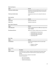
... Ownership Date Memory Installed Memory Available Memory Speed Function Displays the BIOS revision. Displays the ownership date. Displays the current battery status. Using the boot menu does not make any changes to the boot order stored in this to navigate the System... (BIOS) Options Table 1. Displays the memory installed on the computer. Battery Information Option AC Adapter Battery Status Battery Charge State Battery Health Function Displays the AC Adapter information. Boot Menu Press when the Dell logo appears to bring up the diagnostics for the system. Displays the ...
... Ownership Date Memory Installed Memory Available Memory Speed Function Displays the BIOS revision. Displays the ownership date. Displays the current battery status. Using the boot menu does not make any changes to the boot order stored in this to navigate the System... (BIOS) Options Table 1. Displays the memory installed on the computer. Battery Information Option AC Adapter Battery Status Battery Charge State Battery Health Function Displays the AC Adapter information. Boot Menu Press when the Dell logo appears to bring up the diagnostics for the system. Displays the ...
Dell Latitude 10 - ST2e Owner's Manual
Page 23
... Disables boot from the boot order. Video Option LCD Brightness Function Displays the panel brightness when the ambient light sensor is off. • Brightness on Battery • Brightness on -board devices. • Enable/Disable Front Camera Device • Enable/Disable Rear Camera Device • Enable/Disable Media Card Device • Enable...
... Disables boot from the boot order. Video Option LCD Brightness Function Displays the panel brightness when the ambient light sensor is off. • Brightness on Battery • Brightness on -board devices. • Enable/Disable Front Camera Device • Enable/Disable Rear Camera Device • Enable/Disable Media Card Device • Enable...
Dell Latitude 10 - ST2e Owner's Manual
Page 27
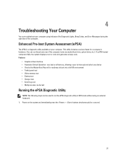
..., and Error Messages during the operation of tests for readiness to boot into a full OS environment • Tablet panel test • Video memory test • Battery test • Charger test • Event log scan • Multiprocessor cache test Running the ePSA Diagnostic Utility NOTE: The following steps can troubleshoot your computer.
..., and Error Messages during the operation of tests for readiness to boot into a full OS environment • Tablet panel test • Video memory test • Battery test • Charger test • Event log scan • Multiprocessor cache test Running the ePSA Diagnostic Utility NOTE: The following steps can troubleshoot your computer.

Dell Latitude 10 - ST2e Owner's Manual
Page 30
..., Super I /O chip failure , Keyboard controller test failure System board failure RAM Read/Write failure Memory failure Real-time clock power fail CMOS battery failure Video BIOS test failure Video card failure CPU - This pattern continues until the system is powered off. cache test failure Processor failure Display ... Super I /O chip failure , Keyboard controller test failure System board failure 4 RAM Read/Write failure Memory failure 5 Real-time clock power fail CMOS battery failure 30 The Power Button LED blinks the corresponding LED codes for the corresponding fault condition.
..., Super I /O chip failure , Keyboard controller test failure System board failure RAM Read/Write failure Memory failure Real-time clock power fail CMOS battery failure Video BIOS test failure Video card failure CPU - This pattern continues until the system is powered off. cache test failure Processor failure Display ... Super I /O chip failure , Keyboard controller test failure System board failure 4 RAM Read/Write failure Memory failure 5 Real-time clock power fail CMOS battery failure 30 The Power Button LED blinks the corresponding LED codes for the corresponding fault condition.
Dell Latitude 10 - ST2e Owner's Manual
Page 34
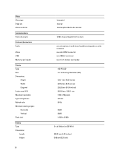
... Memory card reader Display Type Size Dimensions: Height Width Diagonal Active area (X/Y) Maximum resolution Typical brightness Refresh rate Minimum viewing angles: Horizontal Vertical Pixel pitch Battery Type Dimensions Length Height 34 integrated internal Intel Graphics Media Accelerator USB 2.0 based Gigabit LAN via dock one microphone-in and stereo headphones/speakers combo...
... Memory card reader Display Type Size Dimensions: Height Width Diagonal Active area (X/Y) Maximum resolution Typical brightness Refresh rate Minimum viewing angles: Horizontal Vertical Pixel pitch Battery Type Dimensions Length Height 34 integrated internal Intel Graphics Media Accelerator USB 2.0 based Gigabit LAN via dock one microphone-in and stereo headphones/speakers combo...

Dell Latitude 10 - ST2e Owner's Manual
Page 35
... Voltage Temperature range Operating Non-Operating Coin-cell battery AC Adapter Type Input voltage Input current (maximum) Input frequency Output power Output current (30 W) Rated output voltage Temperature range: Operating Non-operating Physical Height ...
... Voltage Temperature range Operating Non-Operating Coin-cell battery AC Adapter Type Input voltage Input current (maximum) Input frequency Output power Output current (30 W) Rated output voltage Temperature range: Operating Non-operating Physical Height ...

