Setup Guide
Page 5
...Optional 12 Enable or Disable Wireless (Optional 14 Set Up Wireless Display (Optional 16 Connect to the Internet (Optional 17 Using Your Inspiron Laptop 20 Right View Features 20 Left View Features 22 Back View Features 26 Front View Features 28 Status Lights and ... Battery Charging 31 Computer Base and Keyboard Features 32 Touch Pad Gestures 36 Multimedia Control Keys 38 Using the Optical Drive 40 Display Features 42 Touch Screen Gestures (Optional 44 Removing and Replacing the Top Cover (Optional 46 Removing and Replacing the Battery 50 Software Features 52 Dell ...
...Optional 12 Enable or Disable Wireless (Optional 14 Set Up Wireless Display (Optional 16 Connect to the Internet (Optional 17 Using Your Inspiron Laptop 20 Right View Features 20 Left View Features 22 Back View Features 26 Front View Features 28 Status Lights and ... Battery Charging 31 Computer Base and Keyboard Features 32 Touch Pad Gestures 36 Multimedia Control Keys 38 Using the Optical Drive 40 Display Features 42 Touch Screen Gestures (Optional 44 Removing and Replacing the Top Cover (Optional 46 Removing and Replacing the Battery 50 Software Features 52 Dell ...
Setup Guide
Page 14
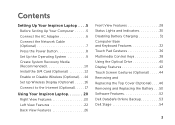
... Internet. Setting Up Your Inspiron Laptop Install the SIM Card (Optional) NOTE: The SIM card slot is not required if you must be within the network of purchase. To access the Internet you are using an EVDO card to the Internet. Remove the battery (see "Removing and Replacing the Battery" on your computer. 2. Turn...
... Internet. Setting Up Your Inspiron Laptop Install the SIM Card (Optional) NOTE: The SIM card slot is not required if you must be within the network of purchase. To access the Internet you are using an EVDO card to the Internet. Remove the battery (see "Removing and Replacing the Battery" on your computer. 2. Turn...
Setup Guide
Page 52
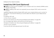
...replace the battery: 1. Using Your Inspiron Laptop Removing and Replacing the Battery WARNING: Before you begin any of fire or explosion. Do not use a battery purchased from other computers. Slide the battery release latch and the battery lock latch to the lock position. 50 Slide the battery into the battery...the battery out of the battery bay. To remove the battery: 1. Slide the battery lock latch to the unlock positions. 3. Turn off the computer and turn it clicks into place. 2. This computer should only use batteries from Dell. WARNING: Before removing the battery, ...
...replace the battery: 1. Using Your Inspiron Laptop Removing and Replacing the Battery WARNING: Before you begin any of fire or explosion. Do not use a battery purchased from other computers. Slide the battery release latch and the battery lock latch to the lock position. 50 Slide the battery into the battery...the battery out of the battery bay. To remove the battery: 1. Slide the battery lock latch to the unlock positions. 3. Turn off the computer and turn it clicks into place. 2. This computer should only use batteries from Dell. WARNING: Before removing the battery, ...
Service Manual
Page 3
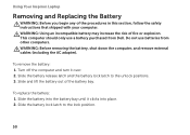
Contents 1 Before You Begin 9 Recommended Tools 9 Turning Off Your Computer 9 Before Working Inside Your Computer 10 2 Top Cover 13 Removing the Top Cover 13 Replacing the Top Cover 14 3 Battery 15 Removing the Battery 15 Replacing the Battery 16 4 Module Cover 17 Removing the Module Cover 17 Replacing the Module Cover 18 5 Memory Module(s 19 Removing the Memory Module(s 19 Contents 3
Contents 1 Before You Begin 9 Recommended Tools 9 Turning Off Your Computer 9 Before Working Inside Your Computer 10 2 Top Cover 13 Removing the Top Cover 13 Replacing the Top Cover 14 3 Battery 15 Removing the Battery 15 Replacing the Battery 16 4 Module Cover 17 Removing the Module Cover 17 Replacing the Module Cover 18 5 Memory Module(s 19 Removing the Memory Module(s 19 Contents 3
Service Manual
Page 5
... 45 Display Panel 46 Removing the Display Panel 46 Replacing the Display Panel 47 Display Cable 48 Removing the Display Cable 48 Replacing the Display Cable 49 Display-Panel Brackets 50 Removing the Display-Panel Brackets 50 Replacing the Display-Panel Brackets 50 11 Hinge Cover 53 ...Removing the Hinge Cover 53 Replacing the Hinge Cover 55 12 Camera Module 57 Removing the Camera Module 57 Replacing the Camera Module 58 13 Coin-Cell Battery 61 Removing the Coin-Cell Battery 61 Replacing the Coin-Cell Battery 62 ...
... 45 Display Panel 46 Removing the Display Panel 46 Replacing the Display Panel 47 Display Cable 48 Removing the Display Cable 48 Replacing the Display Cable 49 Display-Panel Brackets 50 Removing the Display-Panel Brackets 50 Replacing the Display-Panel Brackets 50 11 Hinge Cover 53 ...Removing the Hinge Cover 53 Replacing the Hinge Cover 55 12 Camera Module 57 Removing the Camera Module 57 Replacing the Camera Module 58 13 Coin-Cell Battery 61 Removing the Coin-Cell Battery 61 Replacing the Coin-Cell Battery 62 ...

Service Manual
Page 16
3 2 1 1 battery release latch 3 battery lock latch 2 battery Replacing the Battery 1 Follow the instructions in "Before You Begin" on page 9. 2 Slide the battery into the battery bay until it clicks into place. 3 Slide the battery lock latch to the lock position. 16 Battery
3 2 1 1 battery release latch 3 battery lock latch 2 battery Replacing the Battery 1 Follow the instructions in "Before You Begin" on page 9. 2 Slide the battery into the battery bay until it clicks into place. 3 Slide the battery lock latch to the lock position. 16 Battery

Service Manual
Page 18
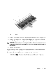
3 2 1 1 tabs 3 captive screw 2 module cover Replacing the Module Cover CAUTION: To avoid damage to the computer, use only the battery designed for this particular Dell computer. 1 Follow the instructions in "Before You Begin" on page 9. 2 Align the tabs on the module cover with the slots on the computer base and snap the module cover into place. 3 Tighten the captive screw that secures the module cover to the computer base. 4 Replace the battery (see "Replacing the Battery" on page 16). 18 Module Cover
3 2 1 1 tabs 3 captive screw 2 module cover Replacing the Module Cover CAUTION: To avoid damage to the computer, use only the battery designed for this particular Dell computer. 1 Follow the instructions in "Before You Begin" on page 9. 2 Align the tabs on the module cover with the slots on the computer base and snap the module cover into place. 3 Tighten the captive screw that secures the module cover to the computer base. 4 Replace the battery (see "Replacing the Battery" on page 16). 18 Module Cover
Service Manual
Page 21
To confirm the amount of memory installed in damage to the computer. 6 Turn on the computer, replace all screws and ensure that no stray screws remain inside the computer. CAUTION: Before turning on the computer. As the computer boots, it ...updates the system configuration information. Failure to your computer and an electrical outlet. Memory 21 2 1 1 tab 2 notch 4 Replace the module cover (see "Replacing the Module Cover" on page 18). 5 Replace the battery (see "Replacing the Battery" on page 16), or connect the AC adapter to do so may result in the computer: Click Start ...
To confirm the amount of memory installed in damage to the computer. 6 Turn on the computer, replace all screws and ensure that no stray screws remain inside the computer. CAUTION: Before turning on the computer. As the computer boots, it ...updates the system configuration information. Failure to your computer and an electrical outlet. Memory 21 2 1 1 tab 2 notch 4 Replace the module cover (see "Replacing the Module Cover" on page 18). 5 Replace the battery (see "Replacing the Battery" on page 16), or connect the AC adapter to do so may result in the computer: Click Start ...

Service Manual
Page 24
Failure to the computer. 24 Optical Drive 2 1 1 optical-drive assembly 2 plastic scribe Replacing the Optical Drive 1 Follow the instructions in damage to do so may result in "Before You Begin" on page 9. 2 Slide the optical-drive assembly into the optical-drive bay until it is fully seated. 3 Replace the module cover (see "Replacing the Module Cover" on page 18). 4 Replace the battery (see "Replacing the Battery" on the computer, replace all screws and ensure that no stray screws remain inside the computer. CAUTION: Before turning on page 16).
Failure to the computer. 24 Optical Drive 2 1 1 optical-drive assembly 2 plastic scribe Replacing the Optical Drive 1 Follow the instructions in damage to do so may result in "Before You Begin" on page 9. 2 Slide the optical-drive assembly into the optical-drive bay until it is fully seated. 3 Replace the module cover (see "Replacing the Module Cover" on page 18). 4 Replace the battery (see "Replacing the Battery" on the computer, replace all screws and ensure that no stray screws remain inside the computer. CAUTION: Before turning on page 16).
Service Manual
Page 27
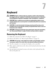
CAUTION: Only a certified service technician should perform repairs on the palm rest. Damage due to replace. Be careful when removing and handling the keyboard. 3 Turn the computer over and open the display as far as a connector on page 15) before working ... slots on the keyboard and release the tabs on the plam rest. 5 Lift and slide the keyboard to the system board, remove the main battery (see the Regulatory Compliance Homepage at dell.com/regulatory_compliance. CAUTION: To help prevent damage to remove the tabs on the keyboard from the slots on your computer).
CAUTION: Only a certified service technician should perform repairs on the palm rest. Damage due to replace. Be careful when removing and handling the keyboard. 3 Turn the computer over and open the display as far as a connector on page 15) before working ... slots on the keyboard and release the tabs on the plam rest. 5 Lift and slide the keyboard to the system board, remove the main battery (see the Regulatory Compliance Homepage at dell.com/regulatory_compliance. CAUTION: To help prevent damage to remove the tabs on the keyboard from the slots on your computer).
Service Manual
Page 30
6 Replace the battery (see "Replacing the Battery" on page 16). 30 Keyboard
6 Replace the battery (see "Replacing the Battery" on page 16). 30 Keyboard

Service Manual
Page 35
CAUTION: Before turning on page 16). Failure to do so may result in damage to the computer base. 8 Replace the battery (see "Replacing the Battery" on the computer, replace all screws and ensure that secure the palm-rest assembly to the computer. Palm-Rest Assembly 35 6 Close the display and turn the computer over. 7 Replace the six screws that no stray screws remain inside the computer.
CAUTION: Before turning on page 16). Failure to do so may result in damage to the computer base. 8 Replace the battery (see "Replacing the Battery" on the computer, replace all screws and ensure that secure the palm-rest assembly to the computer. Palm-Rest Assembly 35 6 Close the display and turn the computer over. 7 Replace the six screws that no stray screws remain inside the computer.

Service Manual
Page 40
Follow the instructions from a source other than Dell, you are installing a communication card from step 4 to the computer. 9 Install the drivers and utilities for your computer, as required. CAUTION: Before turning on page 16). NOTE: If you must install the appropriate drivers and utilities. 40 Wireless Mini-Card(s) Failure to do so may result in damage to step 8 in "Replacing the Palm-Rest Assembly" on page 34. 8 Replace the battery (see "Replacing the Battery" on the computer, replace all screws and ensure that no stray screws remain inside the computer.
Follow the instructions from a source other than Dell, you are installing a communication card from step 4 to the computer. 9 Install the drivers and utilities for your computer, as required. CAUTION: Before turning on page 16). NOTE: If you must install the appropriate drivers and utilities. 40 Wireless Mini-Card(s) Failure to do so may result in damage to step 8 in "Replacing the Palm-Rest Assembly" on page 34. 8 Replace the battery (see "Replacing the Battery" on the computer, replace all screws and ensure that no stray screws remain inside the computer.
Service Manual
Page 44
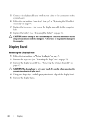
... Using your fingertips, carefully pry up the inside the computer. CAUTION: Before turning on the computer, replace all screws and ensure that secure the display assembly to the computer base. 8 Replace the battery (see "Removing the Display Assembly" on page 41). CAUTION: The display bezel is extremely fragile. Display... Begin" on page 9. 2 Remove the top cover (see "Removing the Top Cover" on page 13). 3 Remove the display assembly (see "Replacing the Battery" on page 16). Failure to do so may result in damage to the computer. 5 Connect the display cable and touch-screen cable to the ...
... Using your fingertips, carefully pry up the inside the computer. CAUTION: Before turning on the computer, replace all screws and ensure that secure the display assembly to the computer base. 8 Replace the battery (see "Removing the Display Assembly" on page 41). CAUTION: The display bezel is extremely fragile. Display... Begin" on page 9. 2 Remove the top cover (see "Removing the Top Cover" on page 13). 3 Remove the display assembly (see "Replacing the Battery" on page 16). Failure to do so may result in damage to the computer. 5 Connect the display cable and touch-screen cable to the ...
Service Manual
Page 55
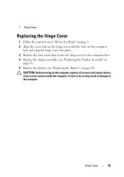
CAUTION: Before turning on the computer, replace all screws and ensure that secure the hinge cover to the computer. Hinge Cover 55 Failure to do so may result in "Before You Begin" ... computer base and snap the hinge cover into place. 3 Replace the four screws that no stray screws remain inside the computer. 1 Hinge Cover Replacing the Hinge Cover 1 Follow the instructions in damage to the computer base. 4 Replace the display assembly (see "Replacing the Display Assembly" on page 43). 5 Replace the battery (see "Replacing the Battery" on page 16).
CAUTION: Before turning on the computer, replace all screws and ensure that secure the hinge cover to the computer. Hinge Cover 55 Failure to do so may result in "Before You Begin" ... computer base and snap the hinge cover into place. 3 Replace the four screws that no stray screws remain inside the computer. 1 Hinge Cover Replacing the Hinge Cover 1 Follow the instructions in damage to the computer base. 4 Replace the display assembly (see "Replacing the Display Assembly" on page 43). 5 Replace the battery (see "Replacing the Battery" on page 16).

Service Manual
Page 58
...the computer. 58 Camera Module CAUTION: Before turning on page 16). Failure to do so may result in "Replacing the Palm-Rest Assembly" on page 34. 7 Replace the battery (see "Replacing the Display Assembly" on page 43). 6 Follow the instructions from step 2 to step 7 in damage ... position and adhere it in place. 3 Replace the display panel (see "Replacing the Display Panel" on page 47). 4 Replace the display bezel (see "Replacing the Display Bezel" on page 45). 5 Replace the display assembly (see "Replacing the Battery" on the computer, replace all screws and ensure that no stray screws...
...the computer. 58 Camera Module CAUTION: Before turning on page 16). Failure to do so may result in "Replacing the Palm-Rest Assembly" on page 34. 7 Replace the battery (see "Replacing the Display Assembly" on page 43). 6 Follow the instructions from step 2 to step 7 in damage ... position and adhere it in place. 3 Replace the display panel (see "Replacing the Display Panel" on page 47). 4 Replace the display bezel (see "Replacing the Display Bezel" on page 45). 5 Replace the display assembly (see "Replacing the Battery" on the computer, replace all screws and ensure that no stray screws...

Service Manual
Page 62
1 2 1 plastic scribe 2 coin-cell battery Replacing the Coin-Cell Battery 1 Follow the instructions in "Before You Begin" on page 9. 2 With the positive side up, snap the coin-cell battery into the battery socket on the system board. 3 Follow the instructions from step 2 to step 7 in "Replacing the Palm-Rest Assembly" on page 34. 4 Replace the battery (see "Replacing the Battery" on page 16). 62 Coin-Cell Battery
1 2 1 plastic scribe 2 coin-cell battery Replacing the Coin-Cell Battery 1 Follow the instructions in "Before You Begin" on page 9. 2 With the positive side up, snap the coin-cell battery into the battery socket on the system board. 3 Follow the instructions from step 2 to step 7 in "Replacing the Palm-Rest Assembly" on page 34. 4 Replace the battery (see "Replacing the Battery" on page 16). 62 Coin-Cell Battery

Service Manual
Page 63
Failure to do so may result in damage to the computer. CAUTION: Before turning on the computer, replace all screws and ensure that no stray screws remain inside the computer. Coin-Cell Battery 63
Failure to do so may result in damage to the computer. CAUTION: Before turning on the computer, replace all screws and ensure that no stray screws remain inside the computer. Coin-Cell Battery 63
Service Manual
Page 67
... or blanks removed from step 2 to step 7 in "Replacing the Palm-Rest Assembly" on page 34. 13 Replace the memory module (see "Replacing the Memory Module(s)" on page 20). 14 Replace the module cover (see "Replacing the Module Cover" on page 18). 15 Replace the battery (see "Replacing the Battery" on the computer. System Board 67 NOTE: After you...
... or blanks removed from step 2 to step 7 in "Replacing the Palm-Rest Assembly" on page 34. 13 Replace the memory module (see "Replacing the Memory Module(s)" on page 20). 14 Replace the module cover (see "Replacing the Module Cover" on page 18). 15 Replace the battery (see "Replacing the Battery" on the computer. System Board 67 NOTE: After you...
Service Manual
Page 76
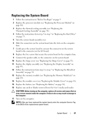
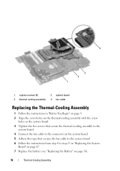
4 3 2 1 1 captive screws (5) 3 thermal-cooling assembly 2 system board 4 fan cable Replacing the Thermal-Cooling Assembly 1 Follow the instructions in "Before You Begin" on page 9. 2 Align the screw holes on the thermal-cooling assembly with the screw ... on the system board. 5 Adhere the tape that secures the fan cable to the system board 6 Follow the instructions from step 4 to step 13 in "Replacing the System Board" on page 67. 7 Replace the battery (see "Replacing the Battery" on page 16). 76 Thermal-Cooling Assembly
4 3 2 1 1 captive screws (5) 3 thermal-cooling assembly 2 system board 4 fan cable Replacing the Thermal-Cooling Assembly 1 Follow the instructions in "Before You Begin" on page 9. 2 Align the screw holes on the thermal-cooling assembly with the screw ... on the system board. 5 Adhere the tape that secures the fan cable to the system board 6 Follow the instructions from step 4 to step 13 in "Replacing the System Board" on page 67. 7 Replace the battery (see "Replacing the Battery" on page 16). 76 Thermal-Cooling Assembly


