Service Manual
Page 1
... are either the entities claiming the marks and names or their products. Dell Inc. Reproduction of data if instructions are trademarks of your computer. A00 Dell™ Inspiron™ 535s/537s/545s/546s Service Manual Technical Overview Before You Begin Computer Cover Support Bracket... Front Bezel Memory PCI and PCI Express Cards Drives Models DCSLE and DCSLF Fans Front I/O Panel Processor System Board Power Supply Battery System...
... are either the entities claiming the marks and names or their products. Dell Inc. Reproduction of data if instructions are trademarks of your computer. A00 Dell™ Inspiron™ 535s/537s/545s/546s Service Manual Technical Overview Before You Begin Computer Cover Support Bracket... Front Bezel Memory PCI and PCI Express Cards Drives Models DCSLE and DCSLF Fans Front I/O Panel Processor System Board Power Supply Battery System...

Service Manual
Page 2
... the locking tabs before you begin working inside the computer. 1. Shut down your operating system, press and hold the power button for removing and installing the components in Turning Off Your Computer and Safety Instructions. WARNING: Before working inside your ... connectors are disconnecting this document may require the following safety guidelines to help to Contents Page Before You Begin Dell™ Inspiron™ 535s/537s/545s/546s Service Manual Technical Specifications Recommended Tools Turning Off Your Computer Safety Instructions This chapter provides procedures for ...
... the locking tabs before you begin working inside the computer. 1. Shut down your operating system, press and hold the power button for removing and installing the components in Turning Off Your Computer and Safety Instructions. WARNING: Before working inside your ... connectors are disconnecting this document may require the following safety guidelines to help to Contents Page Before You Begin Dell™ Inspiron™ 535s/537s/545s/546s Service Manual Technical Specifications Recommended Tools Turning Off Your Computer Safety Instructions This chapter provides procedures for ...

Service Manual
Page 3
3. Press and hold the power button while the system is unplugged to Contents Page Back to ground the system board. While you work, periodically touch an unpainted metal surface to dissipate static electricity, which could harm internal components. Disconnect all attached devices from the computer. 4. Disconnect your computer, ground yourself by touching an unpainted metal surface, such as the metal at the back of the computer. CAUTION: Before touching anything inside your computer and all telephone or network cables from their electrical outlets. 5.
3. Press and hold the power button while the system is unplugged to Contents Page Back to ground the system board. While you work, periodically touch an unpainted metal surface to dissipate static electricity, which could harm internal components. Disconnect all attached devices from the computer. 4. Disconnect your computer, ground yourself by touching an unpainted metal surface, such as the metal at the back of the computer. CAUTION: Before touching anything inside your computer and all telephone or network cables from their electrical outlets. 5.
Service Manual
Page 18
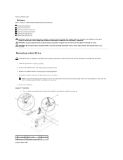
... Removing the Computer Cover). 3. You can use the data cable to keep, back up . 1 securing tab 2 power cable 3 data cable 4 hard drive 5 shoulder screws (4) Inspiron 545s/546s Back to Contents Page Drives Dell™ Inspiron™ 535s/537s/545s/546s Service Manual Removing a Hard Drive Replacing a Hard Drive Removing a Media Card Reader Replacing a Media Card...
... Removing the Computer Cover). 3. You can use the data cable to keep, back up . 1 securing tab 2 power cable 3 data cable 4 hard drive 5 shoulder screws (4) Inspiron 545s/546s Back to Contents Page Drives Dell™ Inspiron™ 535s/537s/545s/546s Service Manual Removing a Hard Drive Replacing a Hard Drive Removing a Media Card Reader Replacing a Media Card...
Service Manual
Page 19
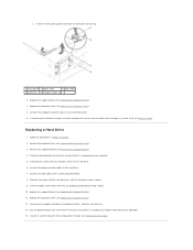
Connect the computer and other devices to the hard drive. 7. Connect the power and data cables to an electrical outlet. 9. Slide the hard drive into the hard drive bay, until the hard drive snaps in Before You Begin. 2. ... any software required for drive configuration changes (see System Setup). Pull the securing tab upwards and slide the hard drive out and up. 1 securing tab 2 power cable 3 data cable 4 hard drive 5 shoulder screws (4) 6. If removing the hard drive changes the drive configuration, ensure that they are properly connected and firmly seated...
Connect the computer and other devices to the hard drive. 7. Connect the power and data cables to an electrical outlet. 9. Slide the hard drive into the hard drive bay, until the hard drive snaps in Before You Begin. 2. ... any software required for drive configuration changes (see System Setup). Pull the securing tab upwards and slide the hard drive out and up. 1 securing tab 2 power cable 3 data cable 4 hard drive 5 shoulder screws (4) 6. If removing the hard drive changes the drive configuration, ensure that they are properly connected and firmly seated...

Service Manual
Page 20
... Press in Before You Begin. 2. Replace the front bezel (see Removing the Front Bezel). 4. Inspiron 535s/537s a. Disconnect the FlexBay USB cable and the power cable from the system board and set it out. 1 power cable 2 FlexBay USB cable 3 securing tab 4 media card reader (not present on all computers)... on the securing tab on the side of the connectors may vary depending on all computers) Inspiron 545s/546s a. Pull the securing tab upwards and slide the media card reader out. 1 power cable 2 FlexBay USB cable 3 securing tab 4 media card reader (not present on your system...
... Press in Before You Begin. 2. Replace the front bezel (see Removing the Front Bezel). 4. Inspiron 535s/537s a. Disconnect the FlexBay USB cable and the power cable from the system board and set it out. 1 power cable 2 FlexBay USB cable 3 securing tab 4 media card reader (not present on all computers)... on the securing tab on the side of the connectors may vary depending on all computers) Inspiron 545s/546s a. Pull the securing tab upwards and slide the media card reader out. 1 power cable 2 FlexBay USB cable 3 securing tab 4 media card reader (not present on your system...

Service Manual
Page 21
... the media card reader is installed before the FlexBay USB cable is a new media card reader installation, remove the break-away metal plate. Connect the power cable to the internal USB connector on . Replace the computer cover (see System Board Components). 8. 8. Align the tip of the media card reader. 9. Connect the...
... the media card reader is installed before the FlexBay USB cable is a new media card reader installation, remove the break-away metal plate. Connect the power cable to the internal USB connector on . Replace the computer cover (see System Board Components). 8. 8. Align the tip of the media card reader. 9. Connect the...

Service Manual
Page 22
...see Removing the Front Bezel). 4. Disconnect the power cable and the data cable from the back of the data cable from the system board and set it out. 1 data cable 2 power cable 3 securing tab 4 shoulder screws (2) 5 optical drive Inspiron 545s/546s a. Follow the procedures in on... the securing tab on the side of the optical drive and slide it aside. Inspiron 535s/537s a. Removing an Optical Drive 1. Pull the securing...
...see Removing the Front Bezel). 4. Disconnect the power cable and the data cable from the back of the data cable from the system board and set it out. 1 data cable 2 power cable 3 securing tab 4 shoulder screws (2) 5 optical drive Inspiron 545s/546s a. Follow the procedures in on... the securing tab on the side of the optical drive and slide it aside. Inspiron 535s/537s a. Removing an Optical Drive 1. Pull the securing...

Service Manual
Page 23
...the Front Bezel). 4. Replacing an Optical Drive 1. If not present, attach the two shoulder screws to the optical drive. 7. Connect the power and data cables to the optical drive. 5. NOTE: The location of the connectors may vary depending on . Follow the procedures in system...the Front Bezel). 9. Remove the front bezel (see Entering System Setup). Check the System Setup for drive operation. 11. 1 data cable 2 power cable 3 securing tab 4 shoulder screws (2) 5 optical drive 6. For more information, see Replacing the Computer Cover). 10. Replace the computer cover ...
...the Front Bezel). 4. Replacing an Optical Drive 1. If not present, attach the two shoulder screws to the optical drive. 7. Connect the power and data cables to the optical drive. 5. NOTE: The location of the connectors may vary depending on . Follow the procedures in system...the Front Bezel). 9. Remove the front bezel (see Entering System Setup). Check the System Setup for drive operation. 11. 1 data cable 2 power cable 3 securing tab 4 shoulder screws (2) 5 optical drive 6. For more information, see Replacing the Computer Cover). 10. Replace the computer cover ...
Service Manual
Page 33
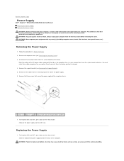
...replace and tighten all the cables from being pinched or crimped. 4. Back to Contents Page Power Supply Dell™ Inspiron™ 535s/537s/545s/546s Service Manual Removing the Power Supply Replacing the Power Supply WARNING: Before working inside your computer, read the safety information that secure the.... Note the routing of the power supply. 6. For Inspiron 535s and 537s, press down on www.dell.com at the following location: www.dell.com/regulatory_compliance. You must route these screws are a key part of the computer. Replacing the Power Supply 1. Follow the procedures in...
...replace and tighten all the cables from being pinched or crimped. 4. Back to Contents Page Power Supply Dell™ Inspiron™ 535s/537s/545s/546s Service Manual Removing the Power Supply Replacing the Power Supply WARNING: Before working inside your computer, read the safety information that secure the.... Note the routing of the power supply. 6. For Inspiron 535s and 537s, press down on www.dell.com at the following location: www.dell.com/regulatory_compliance. You must route these screws are a key part of the computer. Replacing the Power Supply 1. Follow the procedures in...
Service Manual
Page 34
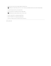
...to the computer chassis. Replace the three screws that secure the power supply to an electrical outlet, and turn them on the side of the power supply. Back to the securing clip on . NOTE: Route the DC power cables under the chassis tabs. Replace the support bracket (see ...Replacing the Computer Cover). 7. 2. Secure all cable connections to make sure they are secure. 5. Connect the DC power cables to prevent the cables from being damaged. 3. The cables must be properly routed to the system board and drives. 4. NOTE: Double-check all...
...to the computer chassis. Replace the three screws that secure the power supply to an electrical outlet, and turn them on the side of the power supply. Back to the securing clip on . NOTE: Route the DC power cables under the chassis tabs. Replace the support bracket (see ...Replacing the Computer Cover). 7. 2. Secure all cable connections to make sure they are secure. 5. Connect the DC power cables to prevent the cables from being damaged. 3. The cables must be properly routed to the system board and drives. 4. NOTE: Double-check all...
Service Manual
Page 35
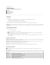
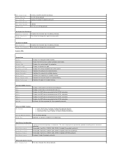
... Processor Level 2 Displays the computer model number. Displays the processor type. Back to Contents Page System Setup Dell™ Inspiron™ 535s/537s/545s/546s Service Manual Overview Entering System Setup Clearing Forgotten Passwords Clearing CMOS Settings Flashing the BIOS Overview Use System.... System Setup Options NOTE: Depending on (or restart) your computer. If you can cause your computer, including installed hardware, power conservation, and security features. System Setup Screens Options List - This field provides context sensitive help based on the top of hard...
... Processor Level 2 Displays the computer model number. Displays the processor type. Back to Contents Page System Setup Dell™ Inspiron™ 535s/537s/545s/546s Service Manual Overview Entering System Setup Clearing Forgotten Passwords Clearing CMOS Settings Flashing the BIOS Overview Use System.... System Setup Options NOTE: Depending on (or restart) your computer. If you can cause your computer, including installed hardware, power conservation, and security features. System Setup Screens Options List - This field provides context sensitive help based on the top of hard...
Service Manual
Page 36
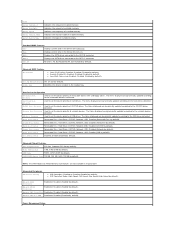
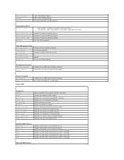
.../DVD; Disabled (Hard Drive by default). Disabled (Enabled by default). Boot Other Device Enabled; On (On by default). USB; Power Management Setup CD/DVD; Standard CMOS Features Date Displays current date in Inspiron 537s Integrated Peripherals USB Device Setting l USB Controller-Enabled or Disabled (Enabled by default). Used to set the device priority...
.../DVD; Disabled (Hard Drive by default). Disabled (Enabled by default). Boot Other Device Enabled; On (On by default). USB; Power Management Setup CD/DVD; Standard CMOS Features Date Displays current date in Inspiron 537s Integrated Peripherals USB Device Setting l USB Controller-Enabled or Disabled (Enabled by default). Used to set the device priority...
Service Manual
Page 37
...Hard Disk; Disabled (Hard Disk by default). Disabled (CDROM by default). Change Supervisor Password Press Enter to the SATA 1 connector. Inspiron 545s System Info System BIOS Info Service Tag Processor Type Processor L2 Cache Memory Installed Memory Available Memory Speed Memory Channel Mode Memory ... Priority Used to the SATA 5 connector. Second Boot Device Removable; Hard Disk; CDROM; ACPI Suspend Type Remote Wake Up Auto Power On Auto Power On Date Auto Power On Time AC Recovery S1(POS); S3(STR) (S3(STR) by default). 0 0:00:00 Off; On; Disabled (Disabled...
...Hard Disk; Disabled (Hard Disk by default). Disabled (CDROM by default). Change Supervisor Password Press Enter to the SATA 1 connector. Inspiron 545s System Info System BIOS Info Service Tag Processor Type Processor L2 Cache Memory Installed Memory Available Memory Speed Memory Channel Mode Memory ... Priority Used to the SATA 5 connector. Second Boot Device Removable; Hard Disk; CDROM; ACPI Suspend Type Remote Wake Up Auto Power On Auto Power On Date Auto Power On Time AC Recovery S1(POS); S3(STR) (S3(STR) by default). 0 0:00:00 Off; On; Disabled (Disabled...
Service Manual
Page 38
...-Enabled or Disabled (Enabled by default). Enabled or Disabled (Enabled by default). IDE; Disabled (Disabled by default). Auto Power On Date 0 Auto Power On Time 0:00:00 AC Recovery Off; Set Supervisor Password Supervisor Password Change Supervisor Password Installed; Press Enter to change ... Onboard LAN Boot ROM SATA Mode Enabled or Disabled (Enabled by default). Power Management Setup ACPI Suspend Type S1(POS); On; Set User Password User Password Change User Password Inspiron 546s Installed; Displays the computer model number. Indicates the amount of installed memory...
...-Enabled or Disabled (Enabled by default). Enabled or Disabled (Enabled by default). IDE; Disabled (Disabled by default). Auto Power On Date 0 Auto Power On Time 0:00:00 AC Recovery Off; Set Supervisor Password Supervisor Password Change Supervisor Password Installed; Press Enter to change ... Onboard LAN Boot ROM SATA Mode Enabled or Disabled (Enabled by default). Power Management Setup ACPI Suspend Type S1(POS); On; Set User Password User Password Change User Password Inspiron 546s Installed; Displays the computer model number. Indicates the amount of installed memory...
Service Manual
Page 39
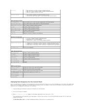
...by default). l 3rd Boot Device-Removable; Boot Other Device No; Power Management Setup ACPI Suspend Type C1E Support Remote Wake Up AC Recovery Auto Power On Auto Power On Date Auto Power On Time S1(POS); Enabled (Enabled by default). Disabled; User ...2. status. Identifies the device installed in the bottom- Hard Disk Boot Priority l 1st Boot Device-Removable; Disabled; Off; You can run the Dell Diagnostics on (or restart) your computer. 3. l AMD Cool 'N' Quiet Function-Enabled; Disabled; Enabled (Enabled by default). Disabled; RAID; ATA...
...by default). l 3rd Boot Device-Removable; Boot Other Device No; Power Management Setup ACPI Suspend Type C1E Support Remote Wake Up AC Recovery Auto Power On Auto Power On Date Auto Power On Time S1(POS); Enabled (Enabled by default). Disabled; User ...2. status. Identifies the device installed in the bottom- Hard Disk Boot Priority l 1st Boot Device-Removable; Disabled; Off; You can run the Dell Diagnostics on (or restart) your computer. 3. l AMD Cool 'N' Quiet Function-Enabled; Disabled; Enabled (Enabled by default). Disabled; RAID; ATA...

Service Manual
Page 41
.... 2. Remove the computer cover (see Replacing the Computer Cover). 8. c. If required, press and hold the power button to enable the password feature. 7. Locate the 3-pin CMOS reset jumper on the CMOS reset jumper pins 2 and 3. b. Inspiron 546s 4. Remove the 2-pin jumper plug from pins 2 and 3 and fix it on pins 2 and 3 to...
.... 2. Remove the computer cover (see Replacing the Computer Cover). 8. c. If required, press and hold the power button to enable the password feature. 7. Locate the 3-pin CMOS reset jumper on the CMOS reset jumper pins 2 and 3. b. Inspiron 546s 4. Remove the 2-pin jumper plug from pins 2 and 3 and fix it on pins 2 and 3 to...
Service Manual
Page 47
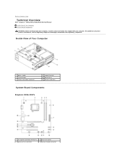
... reader (optional) 2 support bracket 4 optical drive 6 primary hard drive System Board Components Inspiron 535s/537s 1 12 V power connector (ATX12V1) 3 processor fan connector 2 processor socket 4 memory module connector For additional safety best practices information, see the Regulatory Compliance Homepage at www.dell.com/regulatory_compliance. Inside View of Your Computer System Board Components WARNING: Before working...
... reader (optional) 2 support bracket 4 optical drive 6 primary hard drive System Board Components Inspiron 535s/537s 1 12 V power connector (ATX12V1) 3 processor fan connector 2 processor socket 4 memory module connector For additional safety best practices information, see the Regulatory Compliance Homepage at www.dell.com/regulatory_compliance. Inside View of Your Computer System Board Components WARNING: Before working...
SETUP GUIDE
Page 5
... Mouse 9 Connect the Network Cable (Optional) . . . . 10 Connect the Power Cables to Your Display and Computer 11 Windows Vista® Setup 12 Connect to the Internet (Optional 12 Using Your Inspiron™ Desktop 16 Front View Features 16 Back View Features 18 Software Features 20 Solving... Problems 23 Network Problems 23 Power Problems 25 Memory Problems 26 Lockups and Software Problems 27 Using Support Tools 30 Dell Support Center 30 Beep Codes...
... Mouse 9 Connect the Network Cable (Optional) . . . . 10 Connect the Power Cables to Your Display and Computer 11 Windows Vista® Setup 12 Connect to the Internet (Optional 12 Using Your Inspiron™ Desktop 16 Front View Features 16 Back View Features 18 Software Features 20 Solving... Problems 23 Network Problems 23 Power Problems 25 Memory Problems 26 Lockups and Software Problems 27 Using Support Tools 30 Dell Support Center 30 Beep Codes...

SETUP GUIDE
Page 7
..., and a level surface to overheat. WARNING: Before you leave at least 10.2 cm (4 inches) at www.dell.com/ regulatory_compliance. You should never place your computer may cause it is powered on all other sides. To prevent overheating ensure that you begin any of 5.1 cm (2 inches) on . 5...and a minimum of the procedures in an enclosed space, such as a cabinet or drawer when it to place your Inspiron 535s/537s/545s/546s desktop and connecting peripherals. INSPIRON Setting Up Your Inspiron™ Desktop This section provides information about setting up your computer.
..., and a level surface to overheat. WARNING: Before you leave at least 10.2 cm (4 inches) at www.dell.com/ regulatory_compliance. You should never place your computer may cause it is powered on all other sides. To prevent overheating ensure that you begin any of 5.1 cm (2 inches) on . 5...and a minimum of the procedures in an enclosed space, such as a cabinet or drawer when it to place your Inspiron 535s/537s/545s/546s desktop and connecting peripherals. INSPIRON Setting Up Your Inspiron™ Desktop This section provides information about setting up your computer.


