
Microsoft Windows 7: Getting Started Guide
Page 4
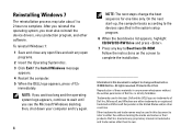
... to refer to Boot from CD-ROM. Follow the instructions on the screen to change the boot sequence for one time only. Printed in the U.S.A. On the next start-up, the computer boots according to the devices specified in the system setup program. 6 When the boot device list appears, highlight CD/DVD/CD-RW Drive and press . 7 Press any open files and exit any key to either...
... to refer to Boot from CD-ROM. Follow the instructions on the screen to change the boot sequence for one time only. Printed in the U.S.A. On the next start-up, the computer boots according to the devices specified in the system setup program. 6 When the boot device list appears, highlight CD/DVD/CD-RW Drive and press . 7 Press any open files and exit any key to either...
Service Manual
Page 1
... the written permission of Dell Inc.; Dell Inc. March 2009 Rev. Dell™ Inspiron™ 535s/537s/545s/546s Service Manual Technical Overview Before You Begin Computer Cover Support Bracket Front Bezel Memory PCI and PCI Express Cards Drives Models DCSLE and DCSLF Fans Front I/O Panel Processor System Board Power Supply Battery System Setup Notes, Cautions, and Warnings NOTE: A NOTE indicates important information that helps you make better use of data if instructions are either the entities...
... the written permission of Dell Inc.; Dell Inc. March 2009 Rev. Dell™ Inspiron™ 535s/537s/545s/546s Service Manual Technical Overview Before You Begin Computer Cover Support Bracket Front Bezel Memory PCI and PCI Express Cards Drives Models DCSLE and DCSLF Fans Front I/O Panel Processor System Board Power Supply Battery System Setup Notes, Cautions, and Warnings NOTE: A NOTE indicates important information that helps you make better use of data if instructions are either the entities...

Service Manual
Page 2
... the Setup Guide that both connectors are correctly oriented and aligned. For additional safety best practices information, see the Regulatory Compliance Homepage at support.dell.com. CAUTION: Only a certified service technician should perform repairs on the cable itself. Turn off . Back to Contents Page Before You Begin Dell™ Inspiron™ 535s/537s/545s/546s Service Manual Technical Specifications Recommended Tools Turning Off Your Computer Safety Instructions This...
... the Setup Guide that both connectors are correctly oriented and aligned. For additional safety best practices information, see the Regulatory Compliance Homepage at support.dell.com. CAUTION: Only a certified service technician should perform repairs on the cable itself. Turn off . Back to Contents Page Before You Begin Dell™ Inspiron™ 535s/537s/545s/546s Service Manual Technical Specifications Recommended Tools Turning Off Your Computer Safety Instructions This...
Service Manual
Page 5
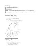
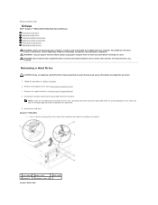
... the card retention bracket. Set the support bracket aside in a secure place. 1 support bracket release latch 2 hinge tabs (2) 3 hinges (2) 4 support bracket Inspiron 545s/546s a. Follow the procedures in Before You Begin. 2. WARNING: Do not operate your computer from the electrical outlet before removing the cover. c. Back to Contents Page Support Bracket Dell™ Inspiron™ 535s/537s/545s/546s Service Manual Removing the Support Bracket Replacing the Support Bracket...
... the card retention bracket. Set the support bracket aside in a secure place. 1 support bracket release latch 2 hinge tabs (2) 3 hinges (2) 4 support bracket Inspiron 545s/546s a. Follow the procedures in Before You Begin. 2. WARNING: Do not operate your computer from the electrical outlet before removing the cover. c. Back to Contents Page Support Bracket Dell™ Inspiron™ 535s/537s/545s/546s Service Manual Removing the Support Bracket Replacing the Support Bracket...
Service Manual
Page 7
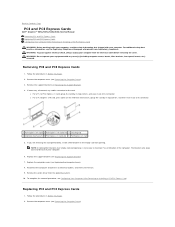
... not operate your computer. Follow the procedures in the empty card-slot opening. NOTE: Installing filler brackets over empty card-slot openings is necessary to Contents Page PCI and PCI Express Cards Dell™ Inspiron™ 535s/537s/545s/546s Service Manual Removing PCI and PCI Express Cards Replacing PCI and PCI Express Cards Configuring Your Computer After Removing or Installing a PCI/PCI Express Card WARNING: Before working inside your computer, read the safety information that shipped with your equipment with any cables connected...
... not operate your computer. Follow the procedures in the empty card-slot opening. NOTE: Installing filler brackets over empty card-slot openings is necessary to Contents Page PCI and PCI Express Cards Dell™ Inspiron™ 535s/537s/545s/546s Service Manual Removing PCI and PCI Express Cards Replacing PCI and PCI Express Cards Configuring Your Computer After Removing or Installing a PCI/PCI Express Card WARNING: Before working inside your computer, read the safety information that shipped with your equipment with any cables connected...

Service Manual
Page 9
Connect the external audio devices to Contents Page Back to the sound card's connectors. Entering System Setup). 2. Enter system setup (see Entering System Setup) 2. Go to Onboard LAN Controller and then change the setting to Disabled. 3. Network Card 1. Connect the network cable to the integrated network connector. Go to Onboard Audio Controller and then change the setting to Enabled. 3. Go to Onboard LAN Controller and then change the setting to Enabled. 3. Enter system setup (see Entering System Setup) 2. Go to Onboard Audio Controller and then change ...
Connect the external audio devices to Contents Page Back to the sound card's connectors. Entering System Setup). 2. Enter system setup (see Entering System Setup) 2. Go to Onboard LAN Controller and then change the setting to Disabled. 3. Network Card 1. Connect the network cable to the integrated network connector. Go to Onboard Audio Controller and then change the setting to Enabled. 3. Go to Onboard LAN Controller and then change the setting to Enabled. 3. Enter system setup (see Entering System Setup) 2. Go to Onboard Audio Controller and then change ...
Service Manual
Page 18
... Removing the Support Bracket). 4. Removing a Hard Drive CAUTION: If you are not replacing the hard drive at a later time. 5. Follow the procedures in on the securing tab on the side of the data cable from the system board and set it aside. Remove the computer cover (see Removing the Computer Cover). 3. Back to Contents Page Drives Dell™ Inspiron™ 535s/537s/545s/546s Service Manual Removing a Hard Drive Replacing a Hard Drive Removing a Media Card Reader Replacing a Media Card Reader Removing an Optical Drive Replacing an Optical Drive WARNING: Before working inside your...
... Removing the Support Bracket). 4. Removing a Hard Drive CAUTION: If you are not replacing the hard drive at a later time. 5. Follow the procedures in on the securing tab on the side of the data cable from the system board and set it aside. Remove the computer cover (see Removing the Computer Cover). 3. Back to Contents Page Drives Dell™ Inspiron™ 535s/537s/545s/546s Service Manual Removing a Hard Drive Replacing a Hard Drive Removing a Media Card Reader Replacing a Media Card Reader Removing an Optical Drive Replacing an Optical Drive WARNING: Before working inside your...
Service Manual
Page 30
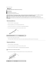
... install ECC memory modules. 4. For additional safety best practices information, see Recommended Memory Configuration). If the memory module is difficult to remove, gently ease the memory module back and forth to Contents Page Memory Dell™ Inspiron™ 535s/537s/545s/546s Service Manual Removing Memory Replacing Memory Recommended Memory Configuration Setting Up Dual Channel Memory Configuration WARNING: Before working inside your computer, read the safety information that shipped with the tab in the memory module connector...
... install ECC memory modules. 4. For additional safety best practices information, see Recommended Memory Configuration). If the memory module is difficult to remove, gently ease the memory module back and forth to Contents Page Memory Dell™ Inspiron™ 535s/537s/545s/546s Service Manual Removing Memory Replacing Memory Recommended Memory Configuration Setting Up Dual Channel Memory Configuration WARNING: Before working inside your computer, read the safety information that shipped with the tab in the memory module connector...
Service Manual
Page 35
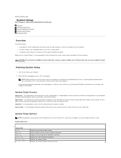
... installed devices, the items listed in even intervals until you see the Microsoft® Windows® desktop, then shut down the system setup screen information for extended periods of your computer. Back to Contents Page System Setup Dell™ Inspiron™ 535s/537s/545s/546s Service Manual Overview Entering System Setup Clearing Forgotten Passwords Clearing CMOS Settings Flashing the BIOS Overview Use System Setup: l To change the system configuration information after you add, change, or remove any hardware in system setup...
... installed devices, the items listed in even intervals until you see the Microsoft® Windows® desktop, then shut down the system setup screen information for extended periods of your computer. Back to Contents Page System Setup Dell™ Inspiron™ 535s/537s/545s/546s Service Manual Overview Entering System Setup Clearing Forgotten Passwords Clearing CMOS Settings Flashing the BIOS Overview Use System Setup: l To change the system configuration information after you add, change, or remove any hardware in system setup...
Service Manual
Page 36
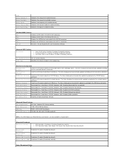
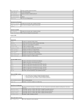
...to the network devices detected. Disabled (Removable Dev. Hard Drive; Cache Memory Installed Memory Available Memory Speed Memory Channel Mode System Memory Type Indicates the amount of network devices. Indicates the amount of installed memory. Indicates the frequency of available memory. Standard CMOS Features Date Displays current date in Inspiron 537s Integrated Peripherals USB Device Setting l USB Controller-Enabled or Disabled (Enabled by default). SATA 1 Displays the SATA drives connected to the SATA 0 connector. Halt On All Errors; Advanced BIOS Features CPU...
...to the network devices detected. Disabled (Removable Dev. Hard Drive; Cache Memory Installed Memory Available Memory Speed Memory Channel Mode System Memory Type Indicates the amount of network devices. Indicates the amount of installed memory. Indicates the frequency of available memory. Standard CMOS Features Date Displays current date in Inspiron 537s Integrated Peripherals USB Device Setting l USB Controller-Enabled or Disabled (Enabled by default). SATA 1 Displays the SATA drives connected to the SATA 0 connector. Halt On All Errors; Advanced BIOS Features CPU...
Service Manual
Page 37
... BIOS Info Service Tag Processor Type Processor L2 Cache Memory Installed Memory Available Memory Speed Memory Channel Mode Memory Technology Displays the computer model number. Indicates the frequency of installed memory. Indicates the type of installed memory. Displays current time in the format (mm:dd:yyyy). Disabled (Enabled by default) Enabled; Hard Disk; On; Off (On by default). Disabled (Disabled by default). On; Last (Off by default). 0 0:00:00 Off; Change Supervisor Password Press Enter to the SATA 1 connector. Set User Password User Password...
... BIOS Info Service Tag Processor Type Processor L2 Cache Memory Installed Memory Available Memory Speed Memory Channel Mode Memory Technology Displays the computer model number. Indicates the frequency of installed memory. Indicates the type of installed memory. Displays current time in the format (mm:dd:yyyy). Disabled (Enabled by default) Enabled; Hard Disk; On; Off (On by default). Disabled (Disabled by default). On; Last (Off by default). 0 0:00:00 Off; Change Supervisor Password Press Enter to the SATA 1 connector. Set User Password User Password...
Service Manual
Page 38
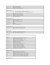
... drives connected to the SATA 3 connector. Displays the SATA drives connected to the SATA 1 connector. l USB Operation Mode-High Speed; Onboard AUDIO Controller Onboard LAN Controller Onboard LAN Boot ROM SATA Mode Enabled or Disabled (Enabled by default). RAID (IDE by default). Not Installed (Not Installed by default). Displays the asset tag for the computer, if present. Indicates the frequency of installed memory. Advanced BIOS Features Remote Wake Up On; Set User Password User Password Change User Password Inspiron 546s Installed; Displays the processor type...
... drives connected to the SATA 3 connector. Displays the SATA drives connected to the SATA 1 connector. l USB Operation Mode-High Speed; Onboard AUDIO Controller Onboard LAN Controller Onboard LAN Boot ROM SATA Mode Enabled or Disabled (Enabled by default). RAID (IDE by default). Not Installed (Not Installed by default). Displays the asset tag for the computer, if present. Indicates the frequency of installed memory. Advanced BIOS Features Remote Wake Up On; Set User Password User Password Change User Password Inspiron 546s Installed; Displays the processor type...
Service Manual
Page 39
... PCI-E 16X Slot; Disabled; l Keyboard Errors-Report; Disabled; Off; Set the supervisor password through this menu. If you see the Microsoft Windows desktop. Enabled (Enabled by default). CD/DVD; Enabled (Enabled by default). right corner of the supervisor password. User Password Set Supervisor Password Displays the status of the user password. l AMD Live!-indicates the AMD Live! Hard Drive; l USB Controller-Enabled or Disabled (Enabled by default). Hard Drive; Do Not Report (Report by default). Power Management Setup ACPI Suspend Type C1E Support Remote Wake...
... PCI-E 16X Slot; Disabled; l Keyboard Errors-Report; Disabled; Off; Set the supervisor password through this menu. If you see the Microsoft Windows desktop. Enabled (Enabled by default). CD/DVD; Enabled (Enabled by default). right corner of the supervisor password. User Password Set Supervisor Password Displays the status of the user password. l AMD Live!-indicates the AMD Live! Hard Drive; l USB Controller-Enabled or Disabled (Enabled by default). Hard Drive; Do Not Report (Report by default). Power Management Setup ACPI Suspend Type C1E Support Remote Wake...
SETUP GUIDE
Page 5
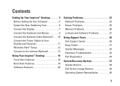
...the Network Cable (Optional) . . . . 10 Connect the Power Cables to Your Display and Computer 11 Windows Vista® Setup 12 Connect to the Internet (Optional 12 Using Your Inspiron™ Desktop 16 Front View Features 16 Back View Features 18 Software Features 20 Solving Problems 23 Network Problems 23 Power Problems 25 Memory Problems 26 Lockups and Software Problems 27 Using Support Tools 30 Dell Support Center 30 Beep Codes 31 System Messages 32 Hardware Troubleshooter 34 Dell Diagnostics 34 System Recovery Options 37 System Restore 38 Dell Factory Image Restore 39...
...the Network Cable (Optional) . . . . 10 Connect the Power Cables to Your Display and Computer 11 Windows Vista® Setup 12 Connect to the Internet (Optional 12 Using Your Inspiron™ Desktop 16 Front View Features 16 Back View Features 18 Software Features 20 Solving Problems 23 Network Problems 23 Power Problems 25 Memory Problems 26 Lockups and Software Problems 27 Using Support Tools 30 Dell Support Center 30 Beep Codes 31 System Messages 32 Hardware Troubleshooter 34 Dell Diagnostics 34 System Recovery Options 37 System Restore 38 Dell Factory Image Restore 39...

SETUP GUIDE
Page 12
... a network port or a broadband device. Setting Up Your Inspiron™ Desktop Connect the Network Cable (Optional) NOTE: The exact location of the network cable to complete your computer setup, but if you have an existing network or Internet connection that the network cable has been securely attached. 10 To attach your computer. Use only an Ethernet cable (RJ45 connector). Do not plug a telephone cable (RJ11 connector) into the network connector. A network connection is shown. A click indicates that uses a cable connection (such as a home cable...
... a network port or a broadband device. Setting Up Your Inspiron™ Desktop Connect the Network Cable (Optional) NOTE: The exact location of the network cable to complete your computer setup, but if you have an existing network or Internet connection that the network cable has been securely attached. 10 To attach your computer. Use only an Ethernet cable (RJ45 connector). Do not plug a telephone cable (RJ11 connector) into the network connector. A network connection is shown. A click indicates that uses a cable connection (such as a home cable...
SETUP GUIDE
Page 20
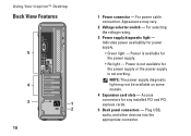
...; No light - Access connectors for power supply. • Green light - For selecting the voltage rating. 3 Power supply diagnostic light - NOTE: The power supply diagnostic light may vary. 2 Voltage selector switch - Appearance may not be available on some models. 4 Expansion card slots - Power is not working. Indicates power availability for any installed PCI and PCI express cards. 5 Back panel connectors - Using Your Inspiron™ Desktop Back View Features 5 4 3 1 2 18 1 Power connector - For power cable connection. Plug USB, audio, and other devices into the...
...; No light - Access connectors for power supply. • Green light - For selecting the voltage rating. 3 Power supply diagnostic light - NOTE: The power supply diagnostic light may vary. 2 Voltage selector switch - Appearance may not be available on some models. 4 Expansion card slots - Power is not working. Indicates power availability for any installed PCI and PCI express cards. 5 Back panel connectors - Using Your Inspiron™ Desktop Back View Features 5 4 3 1 2 18 1 Power connector - For power cable connection. Plug USB, audio, and other devices into the...
SETUP GUIDE
Page 43
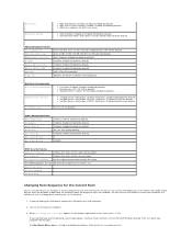
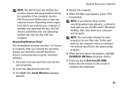
.... Use the Dell Drivers and Utilities disc to load any key to wait until you see the Microsoft® Windows® desktop; Click Exit if the Install Windows message appears. System Recovery Options 4. When the boot device list appears, highlight CD/DVD/CD-RW Drive and press . 7. Reinstalling Windows Vista® The reinstallation process can take 1 to 2 hours to the devices specified in the system setup program. 6. Save and close any open...
.... Use the Dell Drivers and Utilities disc to load any key to wait until you see the Microsoft® Windows® desktop; Click Exit if the Install Windows message appears. System Recovery Options 4. When the boot device list appears, highlight CD/DVD/CD-RW Drive and press . 7. Reinstalling Windows Vista® The reinstallation process can take 1 to 2 hours to the devices specified in the system setup program. 6. Save and close any open...
SETUP GUIDE
Page 52
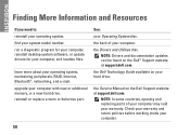
the Service Manual on the Dell™ Support website at support.dell.com. find your computer, and readme files. run a diagnostic program for your computer, reinstall desktop system software, or update drivers for your system model number. the back of your computer may void your computer. upgrade your operating system, maintaining peripherals, RAID, Internet, Bluetooth®, networking, and e-mail. the Drivers and Utilities disc. NOTE: In some countries, opening and replacing parts of your warranty. learn...
the Service Manual on the Dell™ Support website at support.dell.com. find your computer, and readme files. run a diagnostic program for your computer, reinstall desktop system software, or update drivers for your system model number. the back of your computer may void your computer. upgrade your operating system, maintaining peripherals, RAID, Internet, Bluetooth®, networking, and e-mail. the Drivers and Utilities disc. NOTE: In some countries, opening and replacing parts of your warranty. learn...
SETUP GUIDE
Page 54
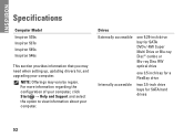
... a FlexBay drive Internally accessible two 3.5-inch drive bays for , and upgrading your computer. For more information regarding the configuration of your computer, click Start → Help and Support and select the option to view information about your computer. INSPIRON Specifications Computer Model Inspiron 535s Inspiron 537s Inspiron 545s Inspiron 546s This section provides information that you may vary by region. NOTE: Offerings may need when setting up, updating drivers for SATA hard drives 52
... a FlexBay drive Internally accessible two 3.5-inch drive bays for , and upgrading your computer. For more information regarding the configuration of your computer, click Start → Help and Support and select the option to view information about your computer. INSPIRON Specifications Computer Model Inspiron 535s Inspiron 537s Inspiron 545s Inspiron 546s This section provides information that you may vary by region. NOTE: Offerings may need when setting up, updating drivers for SATA hard drives 52
Tech Sheet Windows® 7
Page 4
... permission of Dell Inc; Follow the instructions on the screen to wait until you must also reinstall the device drivers, virus protection program, and other countries. Information in this document to refer to Boot from CD-ROM. is subject to complete. Dell Inc. To reinstall Windows 7: 1 Save and close any open programs. 2 Insert the Operating System disc. 3 Click Exit if the Install Windows message...
... permission of Dell Inc; Follow the instructions on the screen to wait until you must also reinstall the device drivers, virus protection program, and other countries. Information in this document to refer to Boot from CD-ROM. is subject to complete. Dell Inc. To reinstall Windows 7: 1 Save and close any open programs. 2 Insert the Operating System disc. 3 Click Exit if the Install Windows message...


