Service Manual
Page 1
...products. All rights reserved. Microsoft and Windows are trademarks of Dell Inc. Dell Inc. Other trademarks and trade names may be used in trademarks and trade names other countries. Dell™ Inspiron™ 535/537/545/546 Service Manual Technical Overview Before You Begin Computer ...Cover Front Bezel Memory PCI and PCI Express Cards Drives Models DCME and DCMF Fans Front I/O Panel Processor System Board Power Supply Battery System...
...products. All rights reserved. Microsoft and Windows are trademarks of Dell Inc. Dell Inc. Other trademarks and trade names may be used in trademarks and trade names other countries. Dell™ Inspiron™ 535/537/545/546 Service Manual Technical Overview Before You Begin Computer ...Cover Front Bezel Memory PCI and PCI Express Cards Drives Models DCME and DCMF Fans Front I/O Panel Processor System Board Power Supply Battery System...
Service Manual
Page 13
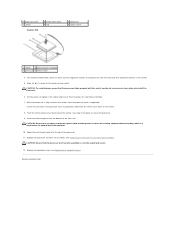
... release lever down and out to release it from the computer (see Removing the Computer Cover). Back to Contents Page Processor Dell™ Inspiron™ 535/537/545/546 Service Manual Removing the Processor Replacing the Processor WARNING: Before working inside your computer, read the safety information that secures it. 5. NOTE: Unless a new heat sink is...
... release lever down and out to release it from the computer (see Removing the Computer Cover). Back to Contents Page Processor Dell™ Inspiron™ 535/537/545/546 Service Manual Removing the Processor Replacing the Processor WARNING: Before working inside your computer, read the safety information that secures it. 5. NOTE: Unless a new heat sink is...
Service Manual
Page 14
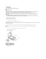
... not fully extended, move it from the socket. Follow the procedures in Before You Begin. 2. Inspiron 535/537/545 1 front alignment notch 2 processor pin-1 indicator 3 rear alignment notch Gently lift the processor to touch the underside of the processor. Leave the release lever extended in the release position so that position. CAUTION: You must position...
... not fully extended, move it from the socket. Follow the procedures in Before You Begin. 2. Inspiron 535/537/545 1 front alignment notch 2 processor pin-1 indicator 3 rear alignment notch Gently lift the processor to touch the underside of the processor. Leave the release lever extended in the release position so that position. CAUTION: You must position...
Service Manual
Page 15
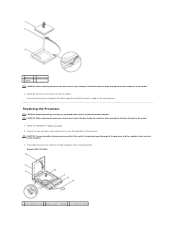
... correctly seated and secure. 12. Apply the new thermal grease to secure the processor. 9. Set the processor lightly in the socket, close the processor cover, if applicable. For Inspiron 535/537/545, orient the front and rear alignment-notches on the processor with the socket, and do not use excessive force when you apply new thermal...
... correctly seated and secure. 12. Apply the new thermal grease to secure the processor. 9. Set the processor lightly in the socket, close the processor cover, if applicable. For Inspiron 535/537/545, orient the front and rear alignment-notches on the processor with the socket, and do not use excessive force when you apply new thermal...
Service Manual
Page 20
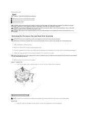
...4. Remove the computer cover (see the Regulatory Compliance Homepage at www.dell.com/regulatory_compliance. Loosen the four captive screws securing the processor fan and heat sink assembly and lift it . 5. Inspiron™ 535/537/545 a. For additional safety best practices information, see Removing the Computer ...-clockwise to remove the fan separately. Back to Contents Page Fans Dell™ Inspiron™ 535/537/545/546 Service Manual Removing the Processor Fan and Heat Sink Assembly Replacing the Processor Fan and Heat Sink Assembly Removing the Chassis Fan Replacing the Chassis...
...4. Remove the computer cover (see the Regulatory Compliance Homepage at www.dell.com/regulatory_compliance. Loosen the four captive screws securing the processor fan and heat sink assembly and lift it . 5. Inspiron™ 535/537/545 a. For additional safety best practices information, see Removing the Computer ...-clockwise to remove the fan separately. Back to Contents Page Fans Dell™ Inspiron™ 535/537/545/546 Service Manual Removing the Processor Fan and Heat Sink Assembly Replacing the Processor Fan and Heat Sink Assembly Removing the Chassis Fan Replacing the Chassis...
Service Manual
Page 21
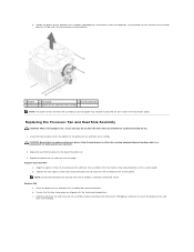
...from the bottom of the processor. 3. Inspiron 535/537/545 a. Hold the processor fan and heat sink fan assembly in the illustration above. CAUTION: Ensure that run between the system board and the fan. 1. Replace the processor fan and heat sink assembly. Replacing the Processor Fan and Heat Sink ...wires that you apply new thermal grease. Inspiron 546 a. b. Place the processor fan and heat sink assembly back onto the bracket. Apply the new thermal grease to secure the processor fan and heat sink assembly. NOTE: Ensure that the processor fan and heat sink assembly is a...
...from the bottom of the processor. 3. Inspiron 535/537/545 a. Hold the processor fan and heat sink fan assembly in the illustration above. CAUTION: Ensure that run between the system board and the fan. 1. Replace the processor fan and heat sink assembly. Replacing the Processor Fan and Heat Sink ...wires that you apply new thermal grease. Inspiron 546 a. b. Place the processor fan and heat sink assembly back onto the bracket. Apply the new thermal grease to secure the processor fan and heat sink assembly. NOTE: Ensure that the processor fan and heat sink assembly is a...
Service Manual
Page 22
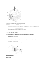
...system board (see System Board Components). 4. This could damage the fan. 1. Follow the procedures in Before You Begin. 2. Inspiron™ 535/537 1 screws (2) 2 chassis fan Inspiron 545/546 Slide the chassis fan towards the front of the computer and lift it up. Remove the computer cover (see ...Replacing the Computer Cover). 6. Connect the processor fan and heat sink assembly cable to an electrical outlet, and turn them ...
...system board (see System Board Components). 4. This could damage the fan. 1. Follow the procedures in Before You Begin. 2. Inspiron™ 535/537 1 screws (2) 2 chassis fan Inspiron 545/546 Slide the chassis fan towards the front of the computer and lift it up. Remove the computer cover (see ...Replacing the Computer Cover). 6. Connect the processor fan and heat sink assembly cable to an electrical outlet, and turn them ...
Service Manual
Page 31
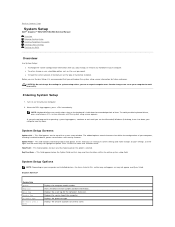
...settings in system setup unless you are an expert computer user. When the DELL logo appears, press immediately. Inspiron 535/537 System Info System BIOS Info Asset Tag Service Tag Processor Type Processor Level 2 Cache Displays the computer model number. Displays the asset tag for... to your computer, including installed hardware, power conservation, and security features. Back to Contents Page System Setup Dell™ Inspiron™ 535/537/545/546 Service Manual Overview Entering System Setup Clearing Forgotten Passwords Clearing CMOS Settings Flashing the BIOS Overview Use ...
...settings in system setup unless you are an expert computer user. When the DELL logo appears, press immediately. Inspiron 535/537 System Info System BIOS Info Asset Tag Service Tag Processor Type Processor Level 2 Cache Displays the computer model number. Displays the asset tag for... to your computer, including installed hardware, power conservation, and security features. Back to Contents Page System Setup Dell™ Inspiron™ 535/537/545/546 Service Manual Overview Entering System Setup Clearing Forgotten Passwords Clearing CMOS Settings Flashing the BIOS Overview Use ...
Service Manual
Page 33
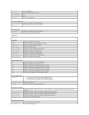
...change the supervisor password Set User Password User Password Change User Password Installed; Displays the service tag of installed memory. Displays the processor type. Indicates the type of the computer. Standard CMOS Features Date Time SATA 0 SATA 1 SATA 4 SATA 5 Halt On...Other Device Enabled; Not Installed (Not Installed by default) Press Enter to change the user password Inspiron 545 System Info System BIOS Info Service Tag Processor Type Processor L2 Cache Memory Installed Memory Available Memory Speed Memory Channel Mode Memory Technology Displays the computer model...
...change the supervisor password Set User Password User Password Change User Password Installed; Displays the service tag of installed memory. Displays the processor type. Indicates the type of the computer. Standard CMOS Features Date Time SATA 0 SATA 1 SATA 4 SATA 5 Halt On...Other Device Enabled; Not Installed (Not Installed by default) Press Enter to change the user password Inspiron 545 System Info System BIOS Info Service Tag Processor Type Processor L2 Cache Memory Installed Memory Available Memory Speed Memory Channel Mode Memory Technology Displays the computer model...
Service Manual
Page 34
...Supervisor Password Change Supervisor Password Installed; On; Last (Off by default) l USB Operation Mode-High Speed; Displays the amount of processor Level 2 cache Indicates the amount of installed memory. Indicates the frequency of installed memory. Standard CMOS Features System Time System Date SATA...the SATA drives connected to the SATA 0 connector. Displays the processor speed. Disabled (Enabled by default) Press Enter to change the supervisor password Set User Password User Password Change User Password Inspiron 546 Installed; Full/Low Speed (High Speed by default) ...
...Supervisor Password Change Supervisor Password Installed; On; Last (Off by default) l USB Operation Mode-High Speed; Displays the amount of processor Level 2 cache Indicates the amount of installed memory. Indicates the frequency of installed memory. Standard CMOS Features System Time System Date SATA...the SATA drives connected to the SATA 0 connector. Displays the processor speed. Disabled (Enabled by default) Press Enter to change the supervisor password Set User Password User Password Change User Password Inspiron 546 Installed; Full/Low Speed (High Speed by default) ...
Service Manual
Page 40
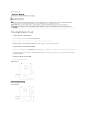
...covers, bezels, filler brackets, front-panel inserts, etc.) removed. Remove the processor (see Removing the Computer Cover). 3. Back to Contents Page System Board Dell™ Inspiron™ 535/537/545/546 Service Manual Removing the System Board Replacing the System Board WARNING: Before... WARNING: To guard against electrical shock, always unplug your computer. Remove the computer cover (see Removing the Processor). 6. Inspiron 535/537 1 screws (6) 2 system board Inspiron 545/546 WARNING: Do not operate your equipment with your computer from the system board. 9. Lift the system...
...covers, bezels, filler brackets, front-panel inserts, etc.) removed. Remove the processor (see Removing the Computer Cover). 3. Back to Contents Page System Board Dell™ Inspiron™ 535/537/545/546 Service Manual Removing the System Board Replacing the System Board WARNING: Before... WARNING: To guard against electrical shock, always unplug your computer. Remove the computer cover (see Removing the Processor). 6. Inspiron 535/537 1 screws (6) 2 system board Inspiron 545/546 WARNING: Do not operate your equipment with your computer from the system board. 9. Lift the system...

Service Manual
Page 41
...system board to the chassis. 3. Replace the processor (see Replacing the Processor Fan and Heat Sink Assembly). Inspiron 535/537 1 back of the computer 2 port retention spring Inspiron 545/546 1 back of the computer. Replace the cables that the processor fan and heat sink assembly is correctly seated and... that secure the system board to ensure that they are not damaged while replacing the sytem board. Replace the processor fan and the heat sink assembly (see Replacing the Processor). 5. Gently align the board into the chassis and slide it towards the back of the computer 2 port...
...system board to the chassis. 3. Replace the processor (see Replacing the Processor Fan and Heat Sink Assembly). Inspiron 535/537 1 back of the computer 2 port retention spring Inspiron 545/546 1 back of the computer. Replace the cables that the processor fan and heat sink assembly is correctly seated and... that secure the system board to ensure that they are not damaged while replacing the sytem board. Replace the processor fan and the heat sink assembly (see Replacing the Processor). 5. Gently align the board into the chassis and slide it towards the back of the computer 2 port...

Setup Guide
Page 22
...Up Your Data It is recommended that you need it and saves power during periods of energy consumed by your activity and by adapting processor speed to your computer over its lifetime. • High performance - This power option offers full performance when you periodically back up computer.... 3. Using Your Inspiron™ Desktop Customizing Your Energy Settings You can use the power options in the Back up files: 1. Microsoft® Windows Vista®...
...Up Your Data It is recommended that you need it and saves power during periods of energy consumed by your activity and by adapting processor speed to your computer over its lifetime. • High performance - This power option offers full performance when you periodically back up computer.... 3. Using Your Inspiron™ Desktop Customizing Your Energy Settings You can use the power options in the Back up files: 1. Microsoft® Windows Vista®...
Setup Guide
Page 55
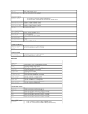
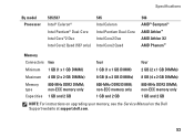
...and 2 GB 1 GB and 2 GB 1 GB and 2 GB NOTE: For instructions on upgrading your memory, see the Service Manual on the Dell Support website at support.dell.com. 53 Specifications By model Processor 535/537 Intel® Celeron® Intel Pentium® Dual-Core Intel Core™2 Duo Intel Core2 Quad... (537 only) 545 Intel Celeron Intel Pentium Dual-Core Intel Core2 Duo Intel Core2 Quad 546 AMD™ Sempron™ AMD ...
...and 2 GB 1 GB and 2 GB 1 GB and 2 GB NOTE: For instructions on upgrading your memory, see the Service Manual on the Dell Support website at support.dell.com. 53 Specifications By model Processor 535/537 Intel® Celeron® Intel Pentium® Dual-Core Intel Core™2 Duo Intel Core2 Quad... (537 only) 545 Intel Celeron Intel Pentium Dual-Core Intel Core2 Duo Intel Core2 Quad 546 AMD™ Sempron™ AMD ...


