Service Manual
Page 2
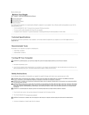
... require the following steps before you are turned off your own personal safety. if you disconnect the cable. Also, before you shut down the operating system. 2. Back to Contents Page Before You Begin Dell™ Inspiron™ 535/537/545/546 Service Manual Technical Specifications Recommended Tools Turning Off Your Computer Safety Instructions This chapter...
... require the following steps before you are turned off your own personal safety. if you disconnect the cable. Also, before you shut down the operating system. 2. Back to Contents Page Before You Begin Dell™ Inspiron™ 535/537/545/546 Service Manual Technical Specifications Recommended Tools Turning Off Your Computer Safety Instructions This chapter...
Service Manual
Page 7
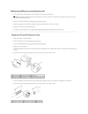
... the Computer Cover). 3. Replace the card retention bracket (see Removing the Card Retention Bracket). 4. Ensure that the card is necessary to electrical outlets, and then turn them on configuring the card, making internal connections, or otherwise customizing it for installation. If you are removing the card permanently, install a filler bracket in...
... the Computer Cover). 3. Replace the card retention bracket (see Removing the Card Retention Bracket). 4. Ensure that the card is necessary to electrical outlets, and then turn them on configuring the card, making internal connections, or otherwise customizing it for installation. If you are removing the card permanently, install a filler bracket in...
Service Manual
Page 8
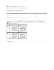
Network Card 1. Enter system setup (see the documentation that should be attached to electrical outlets, and then turn them on location of external connectors, see Configuring Your Computer After Removing or Installing a PCI/PCI Express Card. 4 PCI Express x1 card slot 5 PCI Express ...
Network Card 1. Enter system setup (see the documentation that should be attached to electrical outlets, and then turn them on location of external connectors, see Configuring Your Computer After Removing or Installing a PCI/PCI Express Card. 4 PCI Express x1 card slot 5 PCI Express ...
Service Manual
Page 9
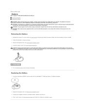
...equivalent type recommended by breaking circuit traces on . 4. WARNING: Do not operate your computer and devices to electrical outlets, and then turn them on the system board. 1 battery release lever 5. Record all the screens in system setup (see Entering System Setup) and restore...socket before removing the cover. Press the battery release lever to the manufacturer's instructions. Back to Contents Page Battery Dell™ Inspiron™ 535/537/545/546 Service Manual Removing the Battery Replacing the Battery WARNING: Before working inside your computer, read the safety information...
...equivalent type recommended by breaking circuit traces on . 4. WARNING: Do not operate your computer and devices to electrical outlets, and then turn them on the system board. 1 battery release lever 5. Record all the screens in system setup (see Entering System Setup) and restore...socket before removing the cover. Press the battery release lever to the manufacturer's instructions. Back to Contents Page Battery Dell™ Inspiron™ 535/537/545/546 Service Manual Removing the Battery Replacing the Battery WARNING: Before working inside your computer, read the safety information...
Service Manual
Page 14
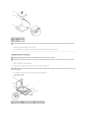
Follow the procedures in the socket to avoid permanent damage to the processor and the computer when you turn on the computer. 3. Gently lift the processor to remove it to that the socket is not fully extended, move it from the socket. Unpack the ... in the release position so that position. Replacing the Processor CAUTION: Ground yourself by touching an unpainted metal surface on the back of the processor. Inspiron 535/537/545 1 front alignment notch 2 processor pin-1 indicator 3 rear alignment notch
Follow the procedures in the socket to avoid permanent damage to the processor and the computer when you turn on the computer. 3. Gently lift the processor to remove it to that the socket is not fully extended, move it from the socket. Unpack the ... in the release position so that position. Replacing the Processor CAUTION: Ground yourself by touching an unpainted metal surface on the back of the processor. Inspiron 535/537/545 1 front alignment notch 2 processor pin-1 indicator 3 rear alignment notch
Service Manual
Page 17
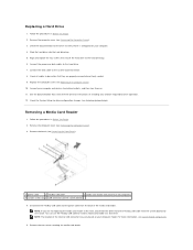
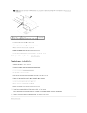
... documentation for your computer model. Check the System Setup for drive operation. 12. You can use the FlexBay USB cable to electrical outlets, and then turn them on your computer. 4. Slide the hard drive into the hard drive bay. 5. NOTE: The location of the media card reader. Follow the procedures in...
... documentation for your computer model. Check the System Setup for drive operation. 12. You can use the FlexBay USB cable to electrical outlets, and then turn them on your computer. 4. Slide the hard drive into the hard drive bay. 5. NOTE: The location of the media card reader. Follow the procedures in...
Service Manual
Page 18
...screw holes in the media card reader with the slot on . Connect the FlexBay USB cable and power cable to electrical outlets, and then turn them on the system board (see System Board Components). 10. Replace the computer cover (see Replacing the Front Bezel). 8. Follow the ...that secure the media card reader to break and remove the metal plate. 5. Connect your computer and devices to electrical outlets, and then turn them on the break-away metal plate and rotate the screwdriver outwards to the FlexBay slot. Remove the computer cover (see Removing the Front...
...screw holes in the media card reader with the slot on . Connect the FlexBay USB cable and power cable to electrical outlets, and then turn them on the system board (see System Board Components). 10. Replace the computer cover (see Replacing the Front Bezel). 8. Follow the ...that secure the media card reader to break and remove the metal plate. 5. Connect your computer and devices to electrical outlets, and then turn them on the break-away metal plate and rotate the screwdriver outwards to the FlexBay slot. Remove the computer cover (see Removing the Front...
Service Manual
Page 19
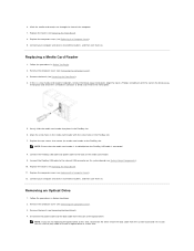
...Contents Page Replace the bezel (see System Setup Options). See the documentation that secure the optical drive to electrical outlets, and then turn them on installing any software required for drive configuration changes (see Entering System Setup). Back to the optical drive. 8. NOTE: ...Slide the optical drive out through the front of SATA connectors may vary based on your computer and devices to their electrical outlets, and turn them on the system board) 5. Connect your computer model. Remove the computer cover (see Replacing the Computer Cover). 9. Gently slide ...
...Contents Page Replace the bezel (see System Setup Options). See the documentation that secure the optical drive to electrical outlets, and then turn them on installing any software required for drive configuration changes (see Entering System Setup). Back to the optical drive. 8. NOTE: ...Slide the optical drive out through the front of SATA connectors may vary based on your computer and devices to their electrical outlets, and turn them on the system board) 5. Connect your computer model. Remove the computer cover (see Replacing the Computer Cover). 9. Gently slide ...
Service Manual
Page 22
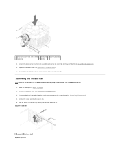
... you are removing the chassis fan. Remove the computer cover (see Replacing the Computer Cover). 6. Follow the procedures in Before You Begin. 2. Inspiron™ 535/537 1 screws (2) 2 chassis fan Inspiron 545/546 Disconnect the chassis fan cable from the chassis fan connector on . Replace the computer cover (see Removing the Computer Cover). 3. Remove... fan towards the front of the computer and lift it up. Connect the processor fan and heat sink assembly cable to an electrical outlet, and turn them on the system board (see System Board Components). 5.
... you are removing the chassis fan. Remove the computer cover (see Replacing the Computer Cover). 6. Follow the procedures in Before You Begin. 2. Inspiron™ 535/537 1 screws (2) 2 chassis fan Inspiron 545/546 Disconnect the chassis fan cable from the chassis fan connector on . Replace the computer cover (see Removing the Computer Cover). 3. Remove... fan towards the front of the computer and lift it up. Connect the processor fan and heat sink assembly cable to an electrical outlet, and turn them on the system board (see System Board Components). 5.
Service Manual
Page 23
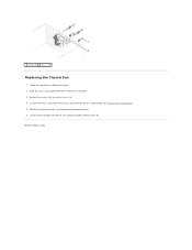
1 screws (4) 2 chassis fan Replacing the Chassis Fan 1. Connect your computer and devices to an electrical outlet, and turn them on the system board (see Replacing the Computer Cover). 6. Back to the chassis fan connector on . Connect the chassis fan cable to Contents Page Replace the screws that secure the chassis fan. 4. Replace the computer cover (see System Board Components). 5. Follow the procedures in place towards the back of the computer. 3. Slide the chassis fan in Before You Begin. 2.
1 screws (4) 2 chassis fan Replacing the Chassis Fan 1. Connect your computer and devices to an electrical outlet, and turn them on the system board (see Replacing the Computer Cover). 6. Back to the chassis fan connector on . Connect the chassis fan cable to Contents Page Replace the screws that secure the chassis fan. 4. Replace the computer cover (see System Board Components). 5. Follow the procedures in place towards the back of the computer. 3. Slide the chassis fan in Before You Begin. 2.

Service Manual
Page 25
5. Connect your computer and devices to Contents Page Replace the computer cover (see Replacing the Computer Cover). 6. Back to an electrical outlet, and turn them on.
5. Connect your computer and devices to Contents Page Replace the computer cover (see Replacing the Computer Cover). 6. Back to an electrical outlet, and turn them on.
Service Manual
Page 27
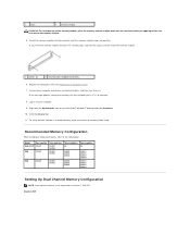
... Memory Configuration While installing or replacing memory, refer to continue. 8. If the message appears stating that the memory is not supported on Inspiron™ 535/537. Right-click the My Computer icon on . If you apply equal force to each end of the memory module. 1 cutouts (2) ...2 securing clip (snapped in position) 6. Log on to electrical outlets, and then turn them on your computer. 9. Inspiron 545 Replace the computer cover (see Replacing...
... Memory Configuration While installing or replacing memory, refer to continue. 8. If the message appears stating that the memory is not supported on Inspiron™ 535/537. Right-click the My Computer icon on . If you apply equal force to each end of the memory module. 1 cutouts (2) ...2 securing clip (snapped in position) 6. Log on to electrical outlets, and then turn them on your computer. 9. Inspiron 545 Replace the computer cover (see Replacing...
Service Manual
Page 30
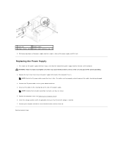
...). 6. NOTE: Route the DC power cables under the chassis tabs. Replacing the Power Supply 1. The cables must be properly routed to an electrical outlet, and turn them on the power supply retention snap(s) and slide the replacement power supply towards the back of the power supply. While pressing down on .
...). 6. NOTE: Route the DC power cables under the chassis tabs. Replacing the Power Supply 1. The cables must be properly routed to an electrical outlet, and turn them on the power supply retention snap(s) and slide the replacement power supply towards the back of the power supply. While pressing down on .
Service Manual
Page 31
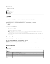
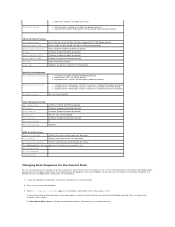
...set the type of your computer and installed devices, the items listed in even intervals until you can cause your computer. 2. Turn on the keyboard is recommended that define the configuration of hard drive installed. The tabbed options contain features that you are an expert... section may not appear, or may result when a key on (or restart) your computer to Contents Page System Setup Dell™ Inspiron™ 535/537/545/546 Service Manual Overview Entering System Setup Clearing Forgotten Passwords Clearing CMOS Settings Flashing the BIOS Overview Use System Setup: ...
...set the type of your computer and installed devices, the items listed in even intervals until you can cause your computer. 2. Turn on the keyboard is recommended that define the configuration of hard drive installed. The tabbed options contain features that you are an expert... section may not appear, or may result when a key on (or restart) your computer to Contents Page System Setup Dell™ Inspiron™ 535/537/545/546 Service Manual Overview Entering System Setup Clearing Forgotten Passwords Clearing CMOS Settings Flashing the BIOS Overview Use System Setup: ...
Service Manual
Page 35
... of the screen, press . On; Enabled (Disabled by default) Disabled; You can run the Dell Diagnostics on (or restart) your computer. 3. If you can also use this feature, for example, to tell the computer to a USB connector. 2. Turn on the Drivers and Utilities media, but you see the Microsoft Windows desktop. When...
... of the screen, press . On; Enabled (Disabled by default) Disabled; You can run the Dell Diagnostics on (or restart) your computer. 3. If you can also use this feature, for example, to tell the computer to a USB connector. 2. Turn on the Drivers and Utilities media, but you see the Microsoft Windows desktop. When...
Service Manual
Page 37
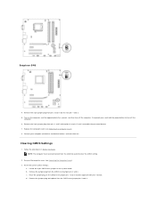
... plug from pins 2 and 3 and fix it on the computer, wait for approximately five seconds, and then turn off the computer. 6. Connect your computer and devices to electrical outlets, and turn off the computer. Locate the 3-pin CMOS reset jumper on the CMOS reset jumper pins 1 and 2 and wait... Begin. Remove the jumper plug and replace it on . NOTE: The computer must be disconnected from the CMOS reset jumper pins 2 and 3. Inspiron 546 4. If required, press and hold the power button to turn them on pins 2 and 3 to clear the CMOS setting. 2. Clearing CMOS Settings 1. b.
... plug from pins 2 and 3 and fix it on the computer, wait for approximately five seconds, and then turn off the computer. 6. Connect your computer and devices to electrical outlets, and turn off the computer. Locate the 3-pin CMOS reset jumper on the CMOS reset jumper pins 1 and 2 and wait... Begin. Remove the jumper plug and replace it on . NOTE: The computer must be disconnected from the CMOS reset jumper pins 2 and 3. Inspiron 546 4. If required, press and hold the power button to turn them on pins 2 and 3 to clear the CMOS setting. 2. Clearing CMOS Settings 1. b.
Service Manual
Page 39
...the system board. 1. Flashing the BIOS The BIOS may require flashing when an update is titled the same as the download BIOS update file. 8. Turn on the screen. Locate the BIOS update file for your desktop. 7. Click Close when the Download Complete window appears. The Save In window appears...Contents Page Double-click the file icon on the desktop and follow the instructions on the computer. 2. Back to your computer at the Dell Support website at support.dell.com. 3. The File Download window appears. 5. Click the down arrow to disk, and then click OK. 5. Click Save this ...
...the system board. 1. Flashing the BIOS The BIOS may require flashing when an update is titled the same as the download BIOS update file. 8. Turn on the screen. Locate the BIOS update file for your desktop. 7. Click Close when the Download Complete window appears. The Save In window appears...Contents Page Double-click the file icon on the desktop and follow the instructions on the computer. 2. Back to your computer at the Dell Support website at support.dell.com. 3. The File Download window appears. 5. Click the down arrow to disk, and then click OK. 5. Click Save this ...

Service Manual
Page 42
Connect your computer and devices to Contents Page Back to an electrical outlet, and turn them (see Replacing Memory). 7. Replace any add-in cards on . Replace the memory modules into the memory sockets at the same locations from which you removed them on the system board (see Replacing the Computer Cover). 9. 6. Replace the computer cover (see Replacing PCI and PCI Express Cards). 8.
Connect your computer and devices to Contents Page Back to an electrical outlet, and turn them (see Replacing Memory). 7. Replace any add-in cards on . Replace the memory modules into the memory sockets at the same locations from which you removed them on the system board (see Replacing the Computer Cover). 9. 6. Replace the computer cover (see Replacing PCI and PCI Express Cards). 8.
Setup Guide
Page 17
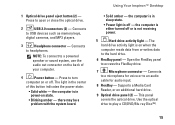
... the optical drive. 2 USB 2.0 connectors (2) - The light in sleep state. • Power light is on state. • Blinking amber - Using Your Inspiron™ Desktop • Solid amber - This panel covers the optical drive. there may be a problem with the system board. NOTE: To connect to... turn computer on the back of this button indicates the power state: • Solid white - Press to USB devices such as memory keys, digital...
... the optical drive. 2 USB 2.0 connectors (2) - The light in sleep state. • Power light is on state. • Blinking amber - Using Your Inspiron™ Desktop • Solid amber - This panel covers the optical drive. there may be a problem with the system board. NOTE: To connect to... turn computer on the back of this button indicates the power state: • Solid white - Press to USB devices such as memory keys, digital...
Setup Guide
Page 25
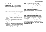
... off - Press a key on the keyboard, move the pointer on the trackpad or a connected mouse, or press the power button to verify that the computer turns on properly. • Ensure that the power supply diagnostic light on the back of the system is on. The computer is not responding - Also bypass... website at support.dell.com). 23 If the power light is solid white and the computer is in sleep state. If the power light is blinking amber - If the power light is solid amber - Ensure that the power strip is turned on. Solving Problems Power Problems If the power light is off...
... off - Press a key on the keyboard, move the pointer on the trackpad or a connected mouse, or press the power button to verify that the computer turns on properly. • Ensure that the power supply diagnostic light on the back of the system is on. The computer is not responding - Also bypass... website at support.dell.com). 23 If the power light is solid white and the computer is in sleep state. If the power light is blinking amber - If the power light is solid amber - Ensure that the power strip is turned on. Solving Problems Power Problems If the power light is off...


