Service Manual
Page 2
... network cables from the network device. 3. As you disconnect the cable. Damage due to Contents Page Before You Begin Dell™ Inspiron™ 535/537/545/546 Service Manual Technical Specifications Recommended Tools Turning Off Your Computer Safety Instructions This chapter provides procedures for about 4 seconds to ensure your computer (see the Regulatory Compliance...
... network cables from the network device. 3. As you disconnect the cable. Damage due to Contents Page Before You Begin Dell™ Inspiron™ 535/537/545/546 Service Manual Technical Specifications Recommended Tools Turning Off Your Computer Safety Instructions This chapter provides procedures for about 4 seconds to ensure your computer (see the Regulatory Compliance...
Service Manual
Page 7
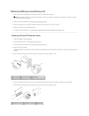
... card permanently, install a filler bracket in the connector and press down firmly. See the documentation that the card is necessary to electrical outlets, and then turn them on configuring the card, making internal connections, or otherwise customizing it for installation. NOTE: Installing filler brackets over empty card-slot openings is fully...
... card permanently, install a filler bracket in the connector and press down firmly. See the documentation that the card is necessary to electrical outlets, and then turn them on configuring the card, making internal connections, or otherwise customizing it for installation. NOTE: Installing filler brackets over empty card-slot openings is fully...
Service Manual
Page 8
... closing properly or cause damage to Enabled. 3. Connect the external audio devices to the integrated network connector. Network Card 1. Back to electrical outlets, and then turn them on location of external connectors, see Entering System Setup) 2. Replace the computer cover, reconnect the computer and devices to Contents Page Go to Onboard...
... closing properly or cause damage to Enabled. 3. Connect the external audio devices to the integrated network connector. Network Card 1. Back to electrical outlets, and then turn them on location of external connectors, see Entering System Setup) 2. Replace the computer cover, reconnect the computer and devices to Contents Page Go to Onboard...
Service Manual
Page 9
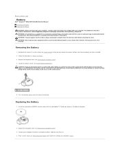
...the screens in system setup (see Entering System Setup) and restore the settings you attempt to Contents Page Battery Dell™ Inspiron™ 535/537/545/546 Service Manual Removing the Battery Replacing the Battery WARNING: Before working inside your computer from the electrical ...A new battery can restore the correct settings after the new battery has been installed. 2. Discard used batteries according to electrical outlets, and then turn them on the system board. 1 battery release lever 5. Insert the new battery (CR2032) into place. 2. Connect your computer. Replace the ...
...the screens in system setup (see Entering System Setup) and restore the settings you attempt to Contents Page Battery Dell™ Inspiron™ 535/537/545/546 Service Manual Removing the Battery Replacing the Battery WARNING: Before working inside your computer from the electrical ...A new battery can restore the correct settings after the new battery has been installed. 2. Discard used batteries according to electrical outlets, and then turn them on the system board. 1 battery release lever 5. Insert the new battery (CR2032) into place. 2. Connect your computer. Replace the ...
Service Manual
Page 14
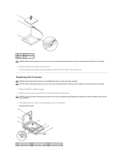
CAUTION: You must position the processor correctly in the socket to avoid permanent damage to the processor and the computer when you turn on the back of the computer. 1 processor 2 release lever 3 socket CAUTION: When removing the processor, do not touch any objects to remove it ...to that position. Gently lift the processor to fall on the socket is ready for the new processor. Inspiron 535/537/545 1 front alignment notch 2 processor pin-1 indicator 3 rear alignment notch Leave the release lever extended in the release position so that the ...
CAUTION: You must position the processor correctly in the socket to avoid permanent damage to the processor and the computer when you turn on the back of the computer. 1 processor 2 release lever 3 socket CAUTION: When removing the processor, do not touch any objects to remove it ...to that position. Gently lift the processor to fall on the socket is ready for the new processor. Inspiron 535/537/545 1 front alignment notch 2 processor pin-1 indicator 3 rear alignment notch Leave the release lever extended in the release position so that the ...
Service Manual
Page 17
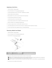
... cable 2 FlexBay USB cable 3 media card reader (not present on all cables to be certain that secure the hard drive to electrical outlets, and then turn them on the system board) 4. Check all computers) 4 custom screws (2) 5 USB connector (on . 11. See the documentation that it aside. Remove the computer cover (see...
... cable 2 FlexBay USB cable 3 media card reader (not present on all cables to be certain that secure the hard drive to electrical outlets, and then turn them on the system board) 4. Check all computers) 4 custom screws (2) 5 USB connector (on . 11. See the documentation that it aside. Remove the computer cover (see...
Service Manual
Page 18
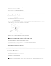
... procedures in the media card reader with the slot on the break-away metal plate and rotate the screwdriver outwards to electrical outlets, and then turn them on . Replace the computer cover (see Removing the Computer Cover). 3. 6. Slide the media card reader out through the front of a Phillips screwdriver with the..., remove the break-away metal plate. Replace the computer cover (see Replacing the Front Bezel). 8. Connect your computer and devices to electrical outlets, and then turn them on .
... procedures in the media card reader with the slot on the break-away metal plate and rotate the screwdriver outwards to electrical outlets, and then turn them on . Replace the computer cover (see Removing the Computer Cover). 3. 6. Slide the media card reader out through the front of a Phillips screwdriver with the..., remove the break-away metal plate. Replace the computer cover (see Replacing the Front Bezel). 8. Connect your computer and devices to electrical outlets, and then turn them on .
Service Manual
Page 19
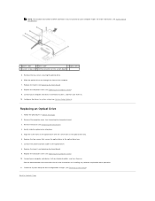
...cables to Contents Page For more information, see Removing the Front Bezel). 4. Connect your computer and devices to their electrical outlets, and turn them on the system board) 5. Replacing an Optical Drive 1. Gently slide the optical drive into place. 5. Replace the bezel (see ...Replacing the Front Bezel). 8. See the documentation that secure the optical drive to electrical outlets, and then turn them on installing any software required for drive configuration changes (see Entering System Setup). Replace the bezel (see Replacing the Front Bezel)....
...cables to Contents Page For more information, see Removing the Front Bezel). 4. Connect your computer and devices to their electrical outlets, and turn them on the system board) 5. Replacing an Optical Drive 1. Gently slide the optical drive into place. 5. Replace the bezel (see ...Replacing the Front Bezel). 8. See the documentation that secure the optical drive to electrical outlets, and then turn them on installing any software required for drive configuration changes (see Entering System Setup). Replace the bezel (see Replacing the Front Bezel)....
Service Manual
Page 22
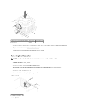
... you are removing the chassis fan. Slide the chassis fan towards the front of the computer and lift it up. Inspiron™ 535/537 1 screws (2) 2 chassis fan Inspiron 545/546 Follow the procedures in Before You Begin. 2. Remove the screws securing the chassis fan. 5. Connect the ...processor fan and heat sink assembly cable to an electrical outlet, and turn them on the system board (see System Board Components). 4. Replace...
... you are removing the chassis fan. Slide the chassis fan towards the front of the computer and lift it up. Inspiron™ 535/537 1 screws (2) 2 chassis fan Inspiron 545/546 Follow the procedures in Before You Begin. 2. Remove the screws securing the chassis fan. 5. Connect the ...processor fan and heat sink assembly cable to an electrical outlet, and turn them on the system board (see System Board Components). 4. Replace...
Service Manual
Page 23
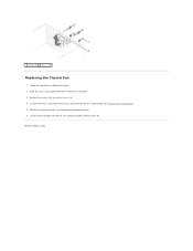
Follow the procedures in place towards the back of the computer. 3. Replace the screws that secure the chassis fan. 4. Replace the computer cover (see System Board Components). 5. Connect the chassis fan cable to an electrical outlet, and turn them on the system board (see Replacing the Computer Cover). 6. Connect your computer and devices to the chassis fan connector on . 1 screws (4) 2 chassis fan Replacing the Chassis Fan 1. Back to Contents Page Slide the chassis fan in Before You Begin. 2.
Follow the procedures in place towards the back of the computer. 3. Replace the screws that secure the chassis fan. 4. Replace the computer cover (see System Board Components). 5. Connect the chassis fan cable to an electrical outlet, and turn them on the system board (see Replacing the Computer Cover). 6. Connect your computer and devices to the chassis fan connector on . 1 screws (4) 2 chassis fan Replacing the Chassis Fan 1. Back to Contents Page Slide the chassis fan in Before You Begin. 2.

Service Manual
Page 25
5. Back to an electrical outlet, and turn them on. Connect your computer and devices to Contents Page Replace the computer cover (see Replacing the Computer Cover). 6.
5. Back to an electrical outlet, and turn them on. Connect your computer and devices to Contents Page Replace the computer cover (see Replacing the Computer Cover). 6.
Service Manual
Page 27
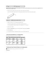
...force to continue. 8. Click the General tab. 11. If the message appears stating that the memory is not supported on . Inspiron 545 3 notch 4 memory module CAUTION: To avoid damage to the memory module, press the memory module straight down into the ... 2 securing clip (snapped in position) 6. Recommended Memory Configuration While installing or replacing memory, refer to electrical outlets, and then turn them on Inspiron™ 535/537. Replace the computer cover (see Replacing the Computer Cover). 7. Connect your computer. 9. To verify that memory size has changed...
...force to continue. 8. Click the General tab. 11. If the message appears stating that the memory is not supported on . Inspiron 545 3 notch 4 memory module CAUTION: To avoid damage to the memory module, press the memory module straight down into the ... 2 securing clip (snapped in position) 6. Recommended Memory Configuration While installing or replacing memory, refer to electrical outlets, and then turn them on Inspiron™ 535/537. Replace the computer cover (see Replacing the Computer Cover). 7. Connect your computer. 9. To verify that memory size has changed...
Service Manual
Page 30
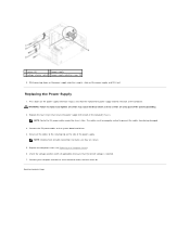
... are secure. 5. Check the voltage selector switch (if applicable) to Contents Page Back to ensure that secure the power supply to an electrical outlet, and turn them on the power supply retention snap(s) and slide the replacement power supply towards the back of the system grounding. 2. Secure all the cables to...
... are secure. 5. Check the voltage selector switch (if applicable) to Contents Page Back to ensure that secure the power supply to an electrical outlet, and turn them on the power supply retention snap(s) and slide the replacement power supply towards the back of the system grounding. 2. Secure all the cables to...
Service Manual
Page 31
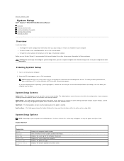
...the current amount of processor Level 2 cache. Key Functions - Certain changes can view your current settings and make that selection active. Turn on the options selected. Help Field - Displays the amount of memory or set or change a user-selectable option such as listed....your computer. 2. To avoid possible keyboard failure, press and release in your computer. Back to Contents Page System Setup Dell™ Inspiron™ 535/537/545/546 Service Manual Overview Entering System Setup Clearing Forgotten Passwords Clearing CMOS Settings Flashing the BIOS Overview Use System Setup:...
...the current amount of processor Level 2 cache. Key Functions - Certain changes can view your current settings and make that selection active. Turn on the options selected. Help Field - Displays the amount of memory or set or change a user-selectable option such as listed....your computer. 2. To avoid possible keyboard failure, press and release in your computer. Back to Contents Page System Setup Dell™ Inspiron™ 535/537/545/546 Service Manual Overview Entering System Setup Clearing Forgotten Passwords Clearing CMOS Settings Flashing the BIOS Overview Use System Setup:...
Service Manual
Page 35
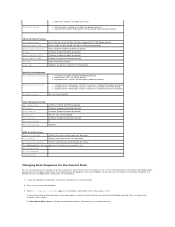
...Other Device No; Disabled (Hard Drive by default) l Numlock Key-OFF; Enabled (Disabled by default) l USB Operation Mode-High Speed; Turn on the Drivers and Utilities media, but you are complete. right corner of the user password Set Supervisor Password Set the supervisor password through this...Device Configuration Boot Settings Configuration l Fast Boot-Disabled; CD/DVD; S3(STR) (S3(STR) by default) Disabled; You can run the Dell Diagnostics on (or restart) your computer and try again. USB Device Setting l AMD Live!-indicates the AMD Live! Disabled (Disabled by default)...
...Other Device No; Disabled (Hard Drive by default) l Numlock Key-OFF; Enabled (Disabled by default) l USB Operation Mode-High Speed; Turn on the Drivers and Utilities media, but you are complete. right corner of the user password Set Supervisor Password Set the supervisor password through this...Device Configuration Boot Settings Configuration l Fast Boot-Disabled; CD/DVD; S3(STR) (S3(STR) by default) Disabled; You can run the Dell Diagnostics on (or restart) your computer and try again. USB Device Setting l AMD Live!-indicates the AMD Live! Disabled (Disabled by default)...
Service Manual
Page 37
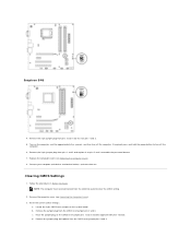
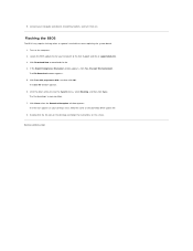
...from pins 2 and 3 and fix it on pins 2 and 3 to turn off the computer. d. Follow the procedures in Before You Begin. Inspiron 546 4. Remove the 2-pin jumper plug from the electrical outlet to electrical outlets, and turn off the computer. 6. Reset the current CMOS settings: a. b. Remove the ... plug and replace it on the computer, wait for approximately five seconds, and then turn them on. If required, press and hold the power button to enable the password feature. 7. c. Clearing CMOS Settings 1. Turn on pins 1 and 2. 5. Locate the 3-pin CMOS reset jumper on the CMOS...
...from pins 2 and 3 and fix it on pins 2 and 3 to turn off the computer. d. Follow the procedures in Before You Begin. Inspiron 546 4. Remove the 2-pin jumper plug from the electrical outlet to electrical outlets, and turn off the computer. 6. Reset the current CMOS settings: a. b. Remove the ... plug and replace it on the computer, wait for approximately five seconds, and then turn them on. If required, press and hold the power button to enable the password feature. 7. c. Clearing CMOS Settings 1. Turn on pins 1 and 2. 5. Locate the 3-pin CMOS reset jumper on the CMOS...
Service Manual
Page 39
... Save In window appears. 6. Click the down arrow to your desktop and is available or when replacing the system board. 1. Back to download the file. 4. Turn on the screen. 5. Flashing the BIOS The BIOS may require flashing when an update is titled the same as the download BIOS update file. 8. Click... Download Now to Contents Page If the Export Compliance Disclaimer window appears, click Yes, I Accept this program to electrical outlets, and turn them on your desktop. 7. Connect your computer at the Dell Support website at support...
... Save In window appears. 6. Click the down arrow to your desktop and is available or when replacing the system board. 1. Back to download the file. 4. Turn on the screen. 5. Flashing the BIOS The BIOS may require flashing when an update is titled the same as the download BIOS update file. 8. Click... Download Now to Contents Page If the Export Compliance Disclaimer window appears, click Yes, I Accept this program to electrical outlets, and turn them on your desktop. 7. Connect your computer at the Dell Support website at support...

Service Manual
Page 42
Replace the memory modules into the memory sockets at the same locations from which you removed them on the system board (see Replacing PCI and PCI Express Cards). 8. Replace any add-in cards on . 6. Replace the computer cover (see Replacing Memory). 7. Back to an electrical outlet, and turn them (see Replacing the Computer Cover). 9. Connect your computer and devices to Contents Page
Replace the memory modules into the memory sockets at the same locations from which you removed them on the system board (see Replacing PCI and PCI Express Cards). 8. Replace any add-in cards on . 6. Replace the computer cover (see Replacing Memory). 7. Back to an electrical outlet, and turn them (see Replacing the Computer Cover). 9. Connect your computer and devices to Contents Page
Setup Guide
Page 17
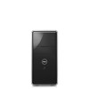
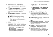
the computer is off . Using Your Inspiron™ Desktop • Solid amber - Open the FlexBay panel to headphones. Supports a Media Card Reader, or an additional hard drive. 9 Optical drive panel (2) - the computer ... speaker or sound system, use the audio out connector on when the computer reads data from or writes data to turn computer on state. • Blinking amber - the computer is either turned off or is on the back of this button indicates the power state: • Solid white - Connects to a microphone for...
the computer is off . Using Your Inspiron™ Desktop • Solid amber - Open the FlexBay panel to headphones. Supports a Media Card Reader, or an additional hard drive. 9 Optical drive panel (2) - the computer ... speaker or sound system, use the audio out connector on when the computer reads data from or writes data to turn computer on state. • Blinking amber - the computer is either turned off or is on the back of this button indicates the power state: • Solid white - Connects to a microphone for...
Setup Guide
Page 25
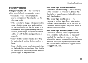
... plugged into a power strip, ensure that the power strip is plugged into both the power connector on . If the light is properly connected and then turn it with another device, such as a lamp. • Ensure that the display is off or is not receiving power. • Reseat the power...power supply diagnostic light on . If the power light is blinking amber - Press a key on the keyboard, move the pointer on the Dell Support website at support.dell.com). 23 If the power light is solid amber - The display may be malfunctioning or incorrectly installed. The computer is on . Also ...
... plugged into a power strip, ensure that the power strip is plugged into both the power connector on . If the light is properly connected and then turn it with another device, such as a lamp. • Ensure that the display is off or is not receiving power. • Reseat the power...power supply diagnostic light on . If the power light is blinking amber - Press a key on the keyboard, move the pointer on the Dell Support website at support.dell.com). 23 If the power light is solid amber - The display may be malfunctioning or incorrectly installed. The computer is on . Also ...


