Service Manual
Page 1
...in trademarks and trade names other countries. Trademarks used in any proprietary interest in this document is strictly forbidden. Dell™ Inspiron™ 535/537/545/546 Service Manual Technical Overview Before You Begin Computer Cover Front Bezel Memory PCI and PCI Express Cards ... Processor System Board Power Supply Battery System Setup Notes, Cautions, and Warnings NOTE: A NOTE indicates important information that helps you make better use of Microsoft Corporation in this document to refer to hardware or loss of data if instructions are trademarks of Dell Inc.; WARNING:...
...in trademarks and trade names other countries. Trademarks used in any proprietary interest in this document is strictly forbidden. Dell™ Inspiron™ 535/537/545/546 Service Manual Technical Overview Before You Begin Computer Cover Front Bezel Memory PCI and PCI Express Cards ... Processor System Board Power Supply Battery System Setup Notes, Cautions, and Warnings NOTE: A NOTE indicates important information that helps you make better use of Microsoft Corporation in this document to refer to hardware or loss of data if instructions are trademarks of Dell Inc.; WARNING:...
Service Manual
Page 2
... that the computer and all attached devices are correctly oriented and aligned. Shut down your operating system, press and hold the power button for removing and installing the components in your computer. Ensure that shipped with your computer. If your computer or see ...cable from the computer. Some cables have performed the steps in reverse order. Back to Contents Page Before You Begin Dell™ Inspiron™ 535/537/545/546 Service Manual Technical Specifications Recommended Tools Turning Off Your Computer Safety Instructions This chapter provides procedures for about 4...
... that the computer and all attached devices are correctly oriented and aligned. Shut down your operating system, press and hold the power button for removing and installing the components in your computer. Ensure that shipped with your computer. If your computer or see ...cable from the computer. Some cables have performed the steps in reverse order. Back to Contents Page Before You Begin Dell™ Inspiron™ 535/537/545/546 Service Manual Technical Specifications Recommended Tools Turning Off Your Computer Safety Instructions This chapter provides procedures for about 4...

Service Manual
Page 3
Press and hold the power button while the system is unplugged to dissipate static electricity, which could harm internal components. While you work, periodically touch an unpainted metal surface to ground the system board. 4. CAUTION: Before touching anything inside your computer and all attached devices from their electrical outlets. 5. Disconnect your computer, ground yourself by touching an unpainted metal surface, such as the metal at the back of the computer. Back to Contents Page
Press and hold the power button while the system is unplugged to dissipate static electricity, which could harm internal components. While you work, periodically touch an unpainted metal surface to ground the system board. 4. CAUTION: Before touching anything inside your computer and all attached devices from their electrical outlets. 5. Disconnect your computer, ground yourself by touching an unpainted metal surface, such as the metal at the back of the computer. Back to Contents Page
Service Manual
Page 16
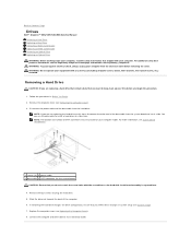
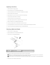
...of the data cable from the system board and set it aside. You can use the data cable to Contents Page Drives Dell™ Inspiron™ 535/537/545/546 Service Manual Removing a Hard Drive Replacing a Hard Drive Removing a Media Card Reader Replacing a Media Card Reader... covers, bezels, filler brackets, front-panel inserts, etc.) removed. For additional safety best practices information, see System Board Components. 1 screws (4) 2 power cable 3 data cable 4 SATA connector (on your equipment with the screwdriver as the hard disk circuit board assembly is exposed here. 4. NOTE: If...
...of the data cable from the system board and set it aside. You can use the data cable to Contents Page Drives Dell™ Inspiron™ 535/537/545/546 Service Manual Removing a Hard Drive Replacing a Hard Drive Removing a Media Card Reader Replacing a Media Card Reader... covers, bezels, filler brackets, front-panel inserts, etc.) removed. For additional safety best practices information, see System Board Components. 1 screws (4) 2 power cable 3 data cable 4 SATA connector (on your equipment with the screwdriver as the hard disk circuit board assembly is exposed here. 4. NOTE: If...
Service Manual
Page 17
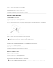
... (see Removing the Computer Cover). 3. Follow the procedures in Before You Begin. 2. Remove the computer cover (see Removing the Front Bezel). 1 power cable 2 FlexBay USB cable 3 media card reader (not present on all cables to electrical outlets, and then turn them on. 11. Connect the... your computer model. Removing a Media Card Reader 1. Remove the computer cover (see Entering System Setup). Disconnect the FlexBay USB cable and the power cable from the system board and set it is configured for the drive to verify that it aside. Remove the two screws securing the media...
... (see Removing the Computer Cover). 3. Follow the procedures in Before You Begin. 2. Remove the computer cover (see Removing the Front Bezel). 1 power cable 2 FlexBay USB cable 3 media card reader (not present on all cables to electrical outlets, and then turn them on. 11. Connect the... your computer model. Removing a Media Card Reader 1. Remove the computer cover (see Entering System Setup). Disconnect the FlexBay USB cable and the power cable from the system board and set it is configured for the drive to verify that it aside. Remove the two screws securing the media...
Service Manual
Page 18
... cover (see Replacing the Computer Cover). 12. Gently slide the media card reader into place in Before You Begin. 2. Connect the FlexBay USB cable and power cable to the internal USB connector on the system board (see System Board Components). 10. Connect your computer and devices to electrical outlets, and then... back of a Phillips screwdriver with the screw holes in Before You Begin. 2. Connect the FlexBay USB cable to the back of the computer. 7. Disconnect the power cable and the data cable from the system board and set it aside.
... cover (see Replacing the Computer Cover). 12. Gently slide the media card reader into place in Before You Begin. 2. Connect the FlexBay USB cable and power cable to the internal USB connector on the system board (see System Board Components). 10. Connect your computer and devices to electrical outlets, and then... back of a Phillips screwdriver with the screw holes in Before You Begin. 2. Connect the FlexBay USB cable to the back of the computer. 7. Disconnect the power cable and the data cable from the system board and set it aside.
Service Manual
Page 19
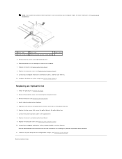
Remove the bezel (see Replacing the Front Bezel). 9. Replace the bezel (see Removing the Front Bezel). 4. For more information, see System Board Components. 1 power cable 2 data cable 3 optical drive 4 custom screws (2) 5 SATA connector (on . 10. Replace the computer cover (see Replacing the Computer Cover). 10. Replacing an Optical ... system board) 5. NOTE: The location and number of the computer. 7. Connect your computer model. Configure the drives in Before You Begin. 2. Connect the power and data cables to Contents Page Check the System Setup for drive operation. 11.
Remove the bezel (see Replacing the Front Bezel). 9. Replace the bezel (see Removing the Front Bezel). 4. For more information, see System Board Components. 1 power cable 2 data cable 3 optical drive 4 custom screws (2) 5 SATA connector (on . 10. Replace the computer cover (see Replacing the Computer Cover). 10. Replacing an Optical ... system board) 5. NOTE: The location and number of the computer. 7. Connect your computer model. Configure the drives in Before You Begin. 2. Connect the power and data cables to Contents Page Check the System Setup for drive operation. 11.
Service Manual
Page 29
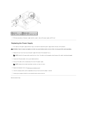
... the system board and the drives. Disconnect the DC power cables from the securing clip on www.dell.com at the following location: www.dell.com/regulatory_compliance. Back to Contents Page Power Supply Dell™ Inspiron™ 535/537/545/546 Service Manual Removing the Power Supply Replacing the Power Supply WARNING: Before working inside your computer, read the...
... the system board and the drives. Disconnect the DC power cables from the securing clip on www.dell.com at the following location: www.dell.com/regulatory_compliance. Back to Contents Page Power Supply Dell™ Inspiron™ 535/537/545/546 Service Manual Removing the Power Supply Replacing the Power Supply WARNING: Before working inside your computer, read the...
Service Manual
Page 30
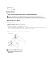
... the computer cover (see Replacing the Computer Cover). 6. Back to make sure they are a key part of the power supply. 1 screws (4) 2 power supply 3 voltage selector switch 4 power supply retention snaps (2) 6. Replace the four screws that the correct voltage is selected. 7. Secure all screws may cause... to the back of the computer. While pressing down on the power supply retention snap(s), slide out the power supply and lift it out. WARNING: Failure to the system board and drives. 4. Replacing the Power Supply 1. Check the voltage selector switch (if applicable) to ensure...
... the computer cover (see Replacing the Computer Cover). 6. Back to make sure they are a key part of the power supply. 1 screws (4) 2 power supply 3 voltage selector switch 4 power supply retention snaps (2) 6. Replace the four screws that the correct voltage is selected. 7. Secure all screws may cause... to the back of the computer. While pressing down on the power supply retention snap(s), slide out the power supply and lift it out. WARNING: Failure to the system board and drives. 4. Replacing the Power Supply 1. Check the voltage selector switch (if applicable) to ensure...
Service Manual
Page 31
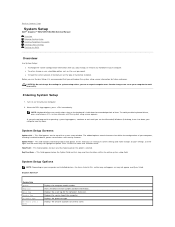
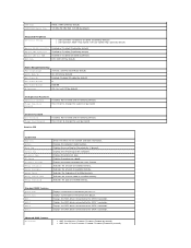
...a key on your computer and installed devices, the items listed in this field you can cause your computer, including installed hardware, power conservation, and security features. Displays the service tag of processor Level 2 cache. This field appears on the options selected. If ...Tag Service Tag Processor Type Processor Level 2 Cache Displays the computer model number. Back to Contents Page System Setup Dell™ Inspiron™ 535/537/545/546 Service Manual Overview Entering System Setup Clearing Forgotten Passwords Clearing CMOS Settings Flashing the BIOS Overview Use System ...
...a key on your computer and installed devices, the items listed in this field you can cause your computer, including installed hardware, power conservation, and security features. Displays the service tag of processor Level 2 cache. This field appears on the options selected. If ...Tag Service Tag Processor Type Processor Level 2 Cache Displays the computer model number. Back to Contents Page System Setup Dell™ Inspiron™ 535/537/545/546 Service Manual Overview Entering System Setup Clearing Forgotten Passwords Clearing CMOS Settings Flashing the BIOS Overview Use System ...
Service Manual
Page 32
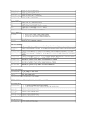
.... Disabled (Disabled by default) Boot Device Configuration Removable Boot Priority Used to the SATA 1 connector. Network; by default) Power Management Setup ACPI Suspend Type S1(POS); Full Speed; Indicates the amount of installed memory. Time Displays current time in the...) Advanced BIOS Features CPU Feature l Limit CPUID Value-Enabled; Disabled (Enabled by default) Module Bay Identifies the device installed in Inspiron 537 Integrated Peripherals USB Device Setting l USB Controller-Enabled or Disabled (Enabled by default) l USB Operation Mode-High Speed; On (On...
.... Disabled (Disabled by default) Boot Device Configuration Removable Boot Priority Used to the SATA 1 connector. Network; by default) Power Management Setup ACPI Suspend Type S1(POS); Full Speed; Indicates the amount of installed memory. Time Displays current time in the...) Advanced BIOS Features CPU Feature l Limit CPUID Value-Enabled; Disabled (Enabled by default) Module Bay Identifies the device installed in Inspiron 537 Integrated Peripherals USB Device Setting l USB Controller-Enabled or Disabled (Enabled by default) l USB Operation Mode-High Speed; On (On...
Service Manual
Page 33
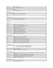
... by default) l Execute Disable Bit-Enabled; Not Installed (Not Installed by default) Press Enter to change the user password Inspiron 545 System Info System BIOS Info Service Tag Processor Type Processor L2 Cache Memory Installed Memory Available Memory Speed Memory Channel Mode ... SATA 1 connector. USB-CDROM; Hard Disk; Disabled (CDROM by default) l Core Multi-Processing-Enabled; Remote Wake Up Auto Power On Auto Power On Date Auto Power On Time AC Recovery On; Not Installed (Not Installed by default) Change Supervisor Password Press Enter to change the supervisor password Set...
... by default) l Execute Disable Bit-Enabled; Not Installed (Not Installed by default) Press Enter to change the user password Inspiron 545 System Info System BIOS Info Service Tag Processor Type Processor L2 Cache Memory Installed Memory Available Memory Speed Memory Channel Mode ... SATA 1 connector. USB-CDROM; Hard Disk; Disabled (CDROM by default) l Core Multi-Processing-Enabled; Remote Wake Up Auto Power On Auto Power On Date Auto Power On Time AC Recovery On; Not Installed (Not Installed by default) Change Supervisor Password Press Enter to change the supervisor password Set...
Service Manual
Page 34
...ROM SATA Mode Enabled or Disabled (Enabled by default) Enabled or Disabled (Enabled by default) Enabled or Disabled (Disabled by default) Power Management Setup ACPI Suspend Type S1(POS); RAID (IDE by default) IDE; On; Indicates the amount of installed memory. Indicates the... the frequency of the computer. Displays the SATA drives connected to change the supervisor password Set User Password User Password Change User Password Inspiron 546 Installed; Last (Off by default) l AMD Cool 'N' Quiet Function-Enabled; Displays the service tag of installed memory. Displays ...
...ROM SATA Mode Enabled or Disabled (Enabled by default) Enabled or Disabled (Enabled by default) Enabled or Disabled (Disabled by default) Power Management Setup ACPI Suspend Type S1(POS); RAID (IDE by default) IDE; On; Indicates the amount of installed memory. Indicates the... the frequency of the computer. Displays the SATA drives connected to change the supervisor password Set User Password User Password Change User Password Inspiron 546 Installed; Last (Off by default) l AMD Cool 'N' Quiet Function-Enabled; Displays the service tag of installed memory. Displays ...
Service Manual
Page 35
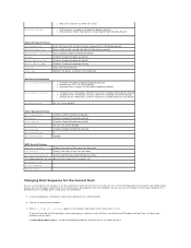
...by default) Disabled; Last (Off by default) Enabled; You can also use this feature, for the Current Boot You can run the Dell Diagnostics on (or restart) your computer and try again. right corner of the user password Set Supervisor Password Set the supervisor password through ...Device-Removable; Disabled (Removable by default) l Keyboard Errors-Report; Disabled (CD/DVD by default) Power Management Setup ACPI Suspend Type C1E Support Remote Wake Up AC Recovery Auto Power On Auto Power On Date Auto Power On Time S1(POS); CD/DVD; Yes (Yes by default) l 3rd Boot Device-Removable;...
...by default) Disabled; Last (Off by default) Enabled; You can also use this feature, for the Current Boot You can run the Dell Diagnostics on (or restart) your computer and try again. right corner of the user password Set Supervisor Password Set the supervisor password through ...Device-Removable; Disabled (Removable by default) l Keyboard Errors-Report; Disabled (CD/DVD by default) Power Management Setup ACPI Suspend Type C1E Support Remote Wake Up AC Recovery Auto Power On Auto Power On Date Auto Power On Time S1(POS); CD/DVD; Yes (Yes by default) l 3rd Boot Device-Removable;...
Service Manual
Page 37
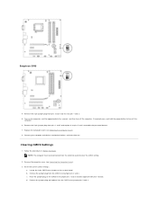
Inspiron 546 4. d. Remove the 2-pin jumper plug from the electrical outlet to enable the password feature. 7. Remove the computer cover (see Replacing the Computer Cover). 8. b. Place the jumper plug on the system board. If required, press and hold the power button to electrical outlets, and turn them on pins 2 and 3 to clear the...
Inspiron 546 4. d. Remove the 2-pin jumper plug from the electrical outlet to enable the password feature. 7. Remove the computer cover (see Replacing the Computer Cover). 8. b. Place the jumper plug on the system board. If required, press and hold the power button to electrical outlets, and turn them on pins 2 and 3 to clear the...
Service Manual
Page 43
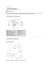
...Contents Page Technical Overview Dell™ Inspiron™ 535/537/545/546 Service Manual Inside View of Your Computer 1 power supply 3 secondary optical drive (optional)* 5 secondary hard drive (optional)* 7 media card reader (optional) 9 card retention bracket * available only on Inspiron™ 545/546... front bezel 6 primary hard drive 8 system board System Board Components Inspiron 535/537 For additional safety best practices information, see the Regulatory Compliance Homepage at www.dell.com/regulatory_compliance. Inside View of Your Computer System Board Components WARNING: Before...
...Contents Page Technical Overview Dell™ Inspiron™ 535/537/545/546 Service Manual Inside View of Your Computer 1 power supply 3 secondary optical drive (optional)* 5 secondary hard drive (optional)* 7 media card reader (optional) 9 card retention bracket * available only on Inspiron™ 545/546... front bezel 6 primary hard drive 8 system board System Board Components Inspiron 535/537 For additional safety best practices information, see the Regulatory Compliance Homepage at www.dell.com/regulatory_compliance. Inside View of Your Computer System Board Components WARNING: Before...
Setup Guide
Page 5
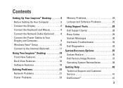
...Connect the Keyboard and Mouse 8 Connect the Network Cable (Optional 8 Connect the Power Cables to Your Display and Computer 9 Windows Vista® Setup 10 Connect to the Internet (Optional 11 Using Your Inspiron™ Desktop 14 Front View Features 14 Back View Features 16 Software Features ...18 Solving Problems 21 Network Problems 21 Power Problems 23 Memory Problems 24 Lockups and Software Problems 25 Using Support Tools 28 Dell Support Center 28 Beep Codes...
...Connect the Keyboard and Mouse 8 Connect the Network Cable (Optional 8 Connect the Power Cables to Your Display and Computer 9 Windows Vista® Setup 10 Connect to the Internet (Optional 11 Using Your Inspiron™ Desktop 14 Front View Features 14 Back View Features 16 Software Features ...18 Solving Problems 21 Network Problems 21 Power Problems 23 Memory Problems 24 Lockups and Software Problems 25 Using Support Tools 28 Dell Support Center 28 Beep Codes...
Setup Guide
Page 7
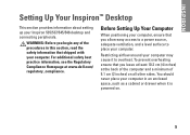
...safety information that shipped with your computer, ensure that you leave at least 10.2 cm (4 inches) at www.dell.com/ regulatory_compliance. WARNING: Before you allow easy access to a power source, adequate ventilation, and a level surface to overheat. To prevent overheating ensure that you begin any of ... of the procedures in an enclosed space, such as a cabinet or drawer when it to place your Inspiron 535/537/545/546 desktop and connecting peripherals. INSPIRON Setting Up Your Inspiron™ Desktop This section provides information about setting up your computer.
...safety information that shipped with your computer, ensure that you leave at least 10.2 cm (4 inches) at www.dell.com/ regulatory_compliance. WARNING: Before you allow easy access to a power source, adequate ventilation, and a level surface to overheat. To prevent overheating ensure that you begin any of ... of the procedures in an enclosed space, such as a cabinet or drawer when it to place your Inspiron 535/537/545/546 desktop and connecting peripherals. INSPIRON Setting Up Your Inspiron™ Desktop This section provides information about setting up your computer.
Setup Guide
Page 11
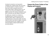
Setting Up Your Inspiron™ Desktop A network connection is not required to complete your computer. Connect the other end of the network cable to the network adapter connector on ... to Your Display and Computer 9 Use only an Ethernet cable (RJ45 connector). Do not plug a telephone cable (RJ11 connector) into the network connector. Connect the Power Cables to a network or broadband device, connect one end of your computer setup, but if you can connect it now.
Setting Up Your Inspiron™ Desktop A network connection is not required to complete your computer. Connect the other end of the network cable to the network adapter connector on ... to Your Display and Computer 9 Use only an Ethernet cable (RJ45 connector). Do not plug a telephone cable (RJ11 connector) into the network connector. Connect the Power Cables to a network or broadband device, connect one end of your computer setup, but if you can connect it now.
Setup Guide
Page 12
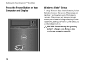
Doing so may take you through several procedures including accepting license agreements, setting preferences, and setting up to 15 minutes to complete. These steps are mandatory and may render your computer unusable. 10 CAUTION: Do not interrupt the operating system's setup process. The screens will take up an Internet connection. Setting Up Your Inspiron™ Desktop Press the Power Button on Your Computer and Display Windows Vista® Setup To set up Windows Vista for the first time, follow the instructions on the screen.
Doing so may take you through several procedures including accepting license agreements, setting preferences, and setting up to 15 minutes to complete. These steps are mandatory and may render your computer unusable. 10 CAUTION: Do not interrupt the operating system's setup process. The screens will take up an Internet connection. Setting Up Your Inspiron™ Desktop Press the Power Button on Your Computer and Display Windows Vista® Setup To set up Windows Vista for the first time, follow the instructions on the screen.


