
Owner's Manual
Page 5
... designed for an earlier Microsoft® Windows® operating system . . . . . 60 A solid blue screen appears 60 Other software problems 61 Media Card Reader Problems 62 Memory Problems 63 Mouse Problems 64 Network Problems 65 Power Problems 66 Printer Problems 67 Scanner Problems 69 Contents 5
... designed for an earlier Microsoft® Windows® operating system . . . . . 60 A solid blue screen appears 60 Other software problems 61 Media Card Reader Problems 62 Memory Problems 63 Mouse Problems 64 Network Problems 65 Power Problems 66 Printer Problems 67 Scanner Problems 69 Contents 5
Owner's Manual
Page 7
... the Computer Cover 99 Inside View of Your Computer 101 System Board Components 102 Power Supply DC Connector Pin Assignments . . . . . 104 Memory 107 Memory Installation Guidelines 108 Installing Memory 109 Removing Memory 111 Cards 111 PCI and PCI Express Cards 112 Bezel 118 Removing the Bezel 118 Replacing the Bezel 119 Drives 120 Recommended...
... the Computer Cover 99 Inside View of Your Computer 101 System Board Components 102 Power Supply DC Connector Pin Assignments . . . . . 104 Memory 107 Memory Installation Guidelines 108 Installing Memory 109 Removing Memory 111 Cards 111 PCI and PCI Express Cards 112 Bezel 118 Removing the Bezel 118 Replacing the Bezel 119 Drives 120 Recommended...
Owner's Manual
Page 13
...Download Now. your computer and operating system and installs the updates appropriate for your operating system and support for components, such as memory, the hard drive, and the operating system • Customer Care - questions NOTE: Corporate, government, and education •... Community - Certified drivers, patches, and software updates • Desktop System Software (DSS)- NOTE: The support.dell.com user interface may vary depending on my computer configuration, product specifications, and white papers • Downloads - What Are You Looking ...
...Download Now. your computer and operating system and installs the updates appropriate for your operating system and support for components, such as memory, the hard drive, and the operating system • Customer Care - questions NOTE: Corporate, government, and education •... Community - Certified drivers, patches, and software updates • Desktop System Software (DSS)- NOTE: The support.dell.com user interface may vary depending on my computer configuration, product specifications, and white papers • Downloads - What Are You Looking ...

Owner's Manual
Page 26
Adjusting the Picture If an error message notifies you that the current resolution and color depth are using too much memory and preventing DVD playback, adjust the display properties: Windows XP: 1 Click the Start button, and then click Control Panel. 2 Under Pick a category, click Appearance and ...
Adjusting the Picture If an error message notifies you that the current resolution and color depth are using too much memory and preventing DVD playback, adjust the display properties: Windows XP: 1 Click the Start button, and then click Control Panel. 2 Under Pick a category, click Appearance and ...
Owner's Manual
Page 30
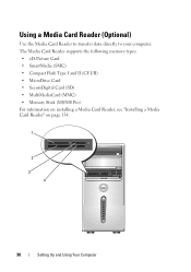
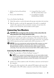
Using a Media Card Reader (Optional) Use the Media Card Reader to transfer data directly to your computer. The Media Card Reader supports the following memory types: • xD-Picture Card • SmartMedia (SMC) • CompactFlash Type I and II (CF I/II) • MicroDrive Card • SecureDigital Card (SD) • MultiMediaCard (MMC) • Memory Stick (MS/MS Pro) For information on installing a Media Card Reader, see "Installing a Media Card Reader" on page 134. 1 2 3 4 30 Setting Up and Using Your Computer
Using a Media Card Reader (Optional) Use the Media Card Reader to transfer data directly to your computer. The Media Card Reader supports the following memory types: • xD-Picture Card • SmartMedia (SMC) • CompactFlash Type I and II (CF I/II) • MicroDrive Card • SecureDigital Card (SD) • MultiMediaCard (MMC) • Memory Stick (MS/MS Pro) For information on installing a Media Card Reader, see "Installing a Media Card Reader" on page 134. 1 2 3 4 30 Setting Up and Using Your Computer
Owner's Manual
Page 31
..., do not force the media or card. Connecting Two Monitors With VGA Connectors 1 Follow the procedures in the connector. 1 xD-Picture Card and SmartMedia (SMC) 3 Memory Stick (MS/MS Pro) 2 CompactFlash Type I and II (CF I/II) and MicroDrive Card 4 SecureDigital Card (SD)/ MultiMediaCard (MMC) To use the Media Card Reader: 1 Check...
..., do not force the media or card. Connecting Two Monitors With VGA Connectors 1 Follow the procedures in the connector. 1 xD-Picture Card and SmartMedia (SMC) 3 Memory Stick (MS/MS Pro) 2 CompactFlash Type I and II (CF I/II) and MicroDrive Card 4 SecureDigital Card (SD)/ MultiMediaCard (MMC) To use the Media Card Reader: 1 Check...
Owner's Manual
Page 34
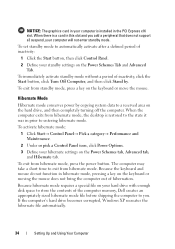
... standby mode, press a key on the Power Schemes Tab and Advanced Tab. To set standby mode to automatically activate after a defined period of the computer memory, Dell creates an appropriately sized hibernate mode file before shipping the computer to entering hibernate mode. Because the keyboard and mouse do not function in prior...
... standby mode, press a key on the Power Schemes Tab and Advanced Tab. To set standby mode to automatically activate after a defined period of the computer memory, Dell creates an appropriately sized hibernate mode file before shipping the computer to entering hibernate mode. Because the keyboard and mouse do not function in prior...
Owner's Manual
Page 38
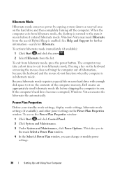
... from hibernate mode. search for further information - Pressing a key on the keyboard or moving the mouse does not bring the computer out of the computer memory, Dell creates an appropriately sized hibernate mode file before it was in hibernate mode. To access the Power Plan Properties window: 1 Click Start and click Control...
... from hibernate mode. search for further information - Pressing a key on the keyboard or moving the mouse does not bring the computer out of the computer memory, Dell creates an appropriately sized hibernate mode file before it was in hibernate mode. To access the Power Plan Properties window: 1 Click Start and click Control...
Owner's Manual
Page 57
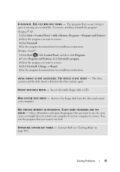
... program you want to remove. 4 Click Uninstall, Change, or Repair. 5 See the program documentation for installation instructions. NOT ENOUGH MEMORY OR RESOURCES. Insert a disk into the drive and try again. S YS T E M D I N - Contact Dell (see "Getting Help" on page 183). I N S E R T B O O T A B L E M E D I S N O T R E A D Y - T H E D E V I C E I A - Close all windows and open is missing an essential file. A R E Q U I L E W A S N O T F O U N D - D L L F I R E D . The program that...
... program you want to remove. 4 Click Uninstall, Change, or Repair. 5 See the program documentation for installation instructions. NOT ENOUGH MEMORY OR RESOURCES. Insert a disk into the drive and try again. S YS T E M D I N - Contact Dell (see "Getting Help" on page 183). I N S E R T B O O T A B L E M E D I S N O T R E A D Y - T H E D E V I C E I A - Close all windows and open is missing an essential file. A R E Q U I L E W A S N O T F O U N D - D L L F I R E D . The program that...
Owner's Manual
Page 63
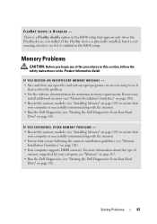
... not using to see if it is successfully communicating with the memory. • Ensure that your computer, see "Memory" on page 167. • Run the Dell Diagnostics (see "Starting the Dell Diagnostics From Your Hard Drive" on page 80). IF YOU RECEIVE AN INSUFFICIENT MEMORY MESSAGE - • Save and close any open files and exit...
... not using to see if it is successfully communicating with the memory. • Ensure that your computer, see "Memory" on page 167. • Run the Dell Diagnostics (see "Starting the Dell Diagnostics From Your Hard Drive" on page 80). IF YOU RECEIVE AN INSUFFICIENT MEMORY MESSAGE - • Save and close any open files and exit...

Owner's Manual
Page 67
...; Ensure that the 12-volt power connector (12V) is receiving electrical power, a device might be malfunctioning or incorrectly installed. • Remove and then reinstall the memory modules (see "System Board Components" on page 116). The computer is securely connected to the system board (see "System Board Components" on page 102). •...
...; Ensure that the 12-volt power connector (12V) is receiving electrical power, a device might be malfunctioning or incorrectly installed. • Remove and then reinstall the memory modules (see "System Board Components" on page 116). The computer is securely connected to the system board (see "System Board Components" on page 102). •...
Owner's Manual
Page 76
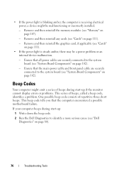
..."Cards" on page 107). - Remove and then reinstall any cards (see "Memory" on page 111). - Remove and then reinstall the graphics card, if applicable... device might emit a series of beeps during start -up : 1 Write down the beep code. 2 Run the Dell Diagnostics to identify a more serious cause (see "System Board Components" on page 80). 76 Troubleshooting Tools Ensure that the... main power cable and front panel cable are securely connected to the system board (see "Dell Diagnostics" on page 102). - This beep code tells you that all power cables are securely connected to...
..."Cards" on page 107). - Remove and then reinstall any cards (see "Memory" on page 111). - Remove and then reinstall the graphics card, if applicable... device might emit a series of beeps during start -up : 1 Write down the beep code. 2 Run the Dell Diagnostics to identify a more serious cause (see "System Board Components" on page 80). 76 Troubleshooting Tools Ensure that the... main power cable and front panel cable are securely connected to the system board (see "Dell Diagnostics" on page 102). - This beep code tells you that all power cables are securely connected to...
Owner's Manual
Page 77
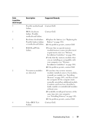
... page 109). 3 If the problem persists, contact Dell. RAM Read/Write failure. 1 Ensure that no special memory module/memory connector placement requirements exist (see "Memory Installation Guidelines" on page 108). 2 Verify that the memory modules that you have identified a faulty module or reinstalled...without error. 2 If available, install good memory of the same type into your computer (see "Installing Memory" on page 142). Video BIOS Test Failure. Contact Dell. or motherboard failure. 2 If the problem persists, contact Dell. BIOS checksum failure. Possible motherboard failure....
... page 109). 3 If the problem persists, contact Dell. RAM Read/Write failure. 1 Ensure that no special memory module/memory connector placement requirements exist (see "Memory Installation Guidelines" on page 108). 2 Verify that the memory modules that you have identified a faulty module or reinstalled...without error. 2 If available, install good memory of the same type into your computer (see "Installing Memory" on page 142). Video BIOS Test Failure. Contact Dell. or motherboard failure. 2 If the problem persists, contact Dell. BIOS checksum failure. Possible motherboard failure....
Owner's Manual
Page 81
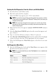
... the button for the option you want . When the DELL logo appears, press immediately. NOTE: The next steps change the boot sequence for your computer. Option Test Memory Test System Exit Function Run the stand-alone memory test Run System Diagnostics Exit the Diagnostics Troubleshooting Tools 81 If...long and the operating system logo appears, continue to wait until you select Test System to run a complete test on your computer. 7 When the Dell Diagnostics Main Menu appears, select the test you want to run . NOTE: It is recommended that appears and press . 5 Type 1 to ...
... the button for the option you want . When the DELL logo appears, press immediately. NOTE: The next steps change the boot sequence for your computer. Option Test Memory Test System Exit Function Run the stand-alone memory test Run System Diagnostics Exit the Diagnostics Troubleshooting Tools 81 If...long and the operating system logo appears, continue to wait until you select Test System to run a complete test on your computer. 7 When the Dell Diagnostics Main Menu appears, select the test you want to run . NOTE: It is recommended that appears and press . 5 Type 1 to ...
Owner's Manual
Page 83
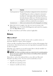
... drivers for your operating system. Ensure that you with your Microsoft Windows operating system. All devices require a driver program. The Dell Diagnostics obtains configuration information for the selected device. Parameters Allows you : • Upgrade your operating system. • Reinstall your..., such as a printer, mouse, or keyboard. Tab Function Configuration Displays your hardware configuration for all devices from system setup, memory, and various internal tests, and it displays the information in the device list in the left pane of the screen. Troubleshooting...
... drivers for your operating system. Ensure that you with your Microsoft Windows operating system. All devices require a driver program. The Dell Diagnostics obtains configuration information for the selected device. Parameters Allows you : • Upgrade your operating system. • Reinstall your..., such as a printer, mouse, or keyboard. Tab Function Configuration Displays your hardware configuration for all devices from system setup, memory, and various internal tests, and it displays the information in the device list in the left pane of the screen. Troubleshooting...

Owner's Manual
Page 107
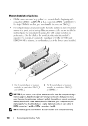
Your computer supports DDR2 memory. NOTICE: Do not install ECC or buffered memory modules. Only unbuffered, non-ECC memory is supported. Removing and Installing Parts 107 For additional information on the type of memory supported by installing memory modules on page 167. DC Power Connector P7 Pin Number 1 2 3 4 Signal Name +5 VDC GND GND +12 VADC 22-AWG Wire Red Black Black Yellow Memory You can increase your computer memory by your computer, see "Memory" on the system board.
Your computer supports DDR2 memory. NOTICE: Do not install ECC or buffered memory modules. Only unbuffered, non-ECC memory is supported. Removing and Installing Parts 107 For additional information on the type of memory supported by installing memory modules on page 167. DC Power Connector P7 Pin Number 1 2 3 4 Signal Name +5 VDC GND GND +12 VADC 22-AWG Wire Red Black Black Yellow Memory You can increase your computer memory by your computer, see "Memory" on the system board.
Owner's Manual
Page 108
... then connectors DIMM_3 and DIMM_4. You should be populated in DIMM connectors 1 and 2 or DIMM connectors 3 and 4. NOTE: Memory purchased from Dell is installed, you must be installed in connectors DIMM_3 and DIMM_4 NOTICE: If you remove your computer may have, even if you... purchased the new modules from Dell. Memory Installation Guidelines • DIMM connectors must install it in connector DIMM_1. • For best performance, memory modules should install your computer warranty. 108 Removing and Installing Parts
... then connectors DIMM_3 and DIMM_4. You should be populated in DIMM connectors 1 and 2 or DIMM connectors 3 and 4. NOTE: Memory purchased from Dell is installed, you must be installed in connectors DIMM_3 and DIMM_4 NOTICE: If you remove your computer may have, even if you... purchased the new modules from Dell. Memory Installation Guidelines • DIMM connectors must install it in connector DIMM_1. • For best performance, memory modules should install your computer warranty. 108 Removing and Installing Parts

Owner's Manual
Page 109
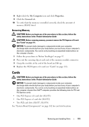
...the safety instructions in "Before You Begin" on page 97. 2 Press the securing clip at each end of the memory module connector. 1 2 3 1 memory connector farthest from your computer, discharge static electricity from processor (DIMM_2) 2 securing clips (2) 3 connector Removing and Installing Parts... 109 CAUTION: Before installing memory, you touch any of your computer's electronic components. NOTICE: To prevent static damage to components inside your body before...
...the safety instructions in "Before You Begin" on page 97. 2 Press the securing clip at each end of the memory module connector. 1 2 3 1 memory connector farthest from your computer, discharge static electricity from processor (DIMM_2) 2 securing clips (2) 3 connector Removing and Installing Parts... 109 CAUTION: Before installing memory, you touch any of your computer's electronic components. NOTICE: To prevent static damage to components inside your body before...

Owner's Manual
Page 110
3 Align the notch on the bottom of the module with the crossbar in the connector. 3 2 1 4 1 cutouts (2) 3 notch 2 memory module 4 crossbar NOTICE: To avoid damage to electrical outlets, and turn them on page 111). 6 Replace the computer cover. NOTICE: To connect a network cable, ...each end of the module. 4 Insert the module into the connector until the module snaps into the computer. 7 Connect your computer and devices to the memory module, press the module straight down into the connector while you insert the module correctly, the securing clips snap into the cutouts at each end...
3 Align the notch on the bottom of the module with the crossbar in the connector. 3 2 1 4 1 cutouts (2) 3 notch 2 memory module 4 crossbar NOTICE: To avoid damage to electrical outlets, and turn them on page 111). 6 Replace the computer cover. NOTICE: To connect a network cable, ...each end of the module. 4 Insert the module into the connector until the module snaps into the computer. 7 Connect your computer and devices to the memory module, press the module straight down into the connector while you insert the module correctly, the securing clips snap into the cutouts at each end...
Owner's Manual
Page 111
...chassis. 1 Follow the procedures in the Product Information Guide. You can do so by touching an unpainted metal surface on the computer chassis.Your Dell™ computer provides the following slots for PCI and PCI Express cards: • One PCI Express x16 card slot (SLOT1) • One... follow the safety instructions in the Product Information Guide. Removing and Installing Parts 111 Cards CAUTION: Before you touch any of memory (RAM) listed. Removing Memory CAUTION: Before you must remove the PCI Express x16 card. You can do so by touching an unpainted metal surface on page...
...chassis. 1 Follow the procedures in the Product Information Guide. You can do so by touching an unpainted metal surface on the computer chassis.Your Dell™ computer provides the following slots for PCI and PCI Express cards: • One PCI Express x16 card slot (SLOT1) • One... follow the safety instructions in the Product Information Guide. Removing and Installing Parts 111 Cards CAUTION: Before you touch any of memory (RAM) listed. Removing Memory CAUTION: Before you must remove the PCI Express x16 card. You can do so by touching an unpainted metal surface on page...


