
User Guide
Page 3
... Off Your Computer 19 Before Working Inside Your Computer 19 3 Chassis Intrusion Switch Removing the Chassis Intrusion Switch 21 Mini Tower Computer 21 Desktop Computer 22 Small Form Factor Computer 23 Ultra Small Form Factor Computer 24 Replacing the Chassis Intrusion Switch 24 Resetting the Chassis Intrusion Detector ...Mini Tower Computer About Your Mini Tower Computer 25 Front View 25 Back View 27 Back-Panel Connectors 28 Inside Your Computer 30 System Board Components 32 Jumper Settings 33 Mini Tower Computer Specifications 35 Removing the Computer Cover 41 Contents 3
... Off Your Computer 19 Before Working Inside Your Computer 19 3 Chassis Intrusion Switch Removing the Chassis Intrusion Switch 21 Mini Tower Computer 21 Desktop Computer 22 Small Form Factor Computer 23 Ultra Small Form Factor Computer 24 Replacing the Chassis Intrusion Switch 24 Resetting the Chassis Intrusion Detector ...Mini Tower Computer About Your Mini Tower Computer 25 Front View 25 Back View 27 Back-Panel Connectors 28 Inside Your Computer 30 System Board Components 32 Jumper Settings 33 Mini Tower Computer Specifications 35 Removing the Computer Cover 41 Contents 3

User Guide
Page 5
... 97 Front View 97 Back View 98 Back-Panel Connectors 99 Inside Your Computer 100 System Board Components 102 Jumper Settings 103 Desktop Computer Specifications 105 Removing the Computer Cover 111 I/O Panel 113 Removing the I/O Panel 113 Replacing the I/O Panel 114 Drives 115 General Installation Guidelines 115 Connecting ...
... 97 Front View 97 Back View 98 Back-Panel Connectors 99 Inside Your Computer 100 System Board Components 102 Jumper Settings 103 Desktop Computer Specifications 105 Removing the Computer Cover 111 I/O Panel 113 Removing the I/O Panel 113 Replacing the I/O Panel 114 Drives 115 General Installation Guidelines 115 Connecting ...
User Guide
Page 6
... Form Factor Computer About Your Small Form Factor Computer 157 Front View 157 Back View 158 Back-Panel Connectors 159 Inside Your Computer 160 System Board Components 162 Jumper Settings 163 Small Form Factor Computer Specifications 165 Removing the Computer Cover 171 I/O Panel 173 Removing the I/O Panel 173 Replacing the I/O Panel...
... Form Factor Computer About Your Small Form Factor Computer 157 Front View 157 Back View 158 Back-Panel Connectors 159 Inside Your Computer 160 System Board Components 162 Jumper Settings 163 Small Form Factor Computer Specifications 165 Removing the Computer Cover 171 I/O Panel 173 Removing the I/O Panel 173 Replacing the I/O Panel...

User Guide
Page 7
... View 201 Side View 202 Back View 203 Back-Panel Connectors 203 Connecting a VGA Monitor 204 Connecting Two Monitors 205 Inside Your Computer 205 System Board Components 207 Jumper Settings 207 Contents 7
... View 201 Side View 202 Back View 203 Back-Panel Connectors 203 Connecting a VGA Monitor 204 Connecting Two Monitors 205 Inside Your Computer 205 System Board Components 207 Jumper Settings 207 Contents 7
User Guide
Page 10
10 Replacing the System Board Removing the System Board: Mini Tower, Desktop, and Small Form Factor Computers 263 Mini Tower System Board Screws 264 Desktop System Board Screws 265 Small Form Factor System Board Screws 266 Replacing the System Board: Mini Tower, Desktop, and Small Form Factor Computers 266 11 Memory DDR2 Memory Overview 267 ... Drivers and the Operating System Drivers 277 What Is a Driver 277 Identifying Drivers 277 Reinstalling Drivers and Utilities 278 Using Windows XP Device Driver Rollback 278 Using the Optional Drivers and Utilities CD 278 10 Contents
10 Replacing the System Board Removing the System Board: Mini Tower, Desktop, and Small Form Factor Computers 263 Mini Tower System Board Screws 264 Desktop System Board Screws 265 Small Form Factor System Board Screws 266 Replacing the System Board: Mini Tower, Desktop, and Small Form Factor Computers 266 11 Memory DDR2 Memory Overview 267 ... Drivers and the Operating System Drivers 277 What Is a Driver 277 Identifying Drivers 277 Reinstalling Drivers and Utilities 278 Using Windows XP Device Driver Rollback 278 Using the Optional Drivers and Utilities CD 278 10 Contents
User Guide
Page 20
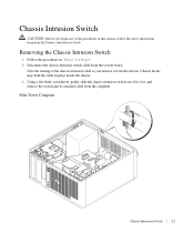
...5 Remove the computer cover: • Remove the mini tower computer cover. • Remove the desktop computer cover. • Remove the small form factor computer cover. • Remove the ultra small... connector pins. As you work, periodically touch an unpainted metal surface to ground the system board. 4 If applicable, remove the computer stand (for instructions, see the documentation that could ... to servicing that both connectors are disconnecting this type of the computer. www.dell.com | support.dell.com CAUTION: Many repairs may only be done by the online or telephone service...
...5 Remove the computer cover: • Remove the mini tower computer cover. • Remove the desktop computer cover. • Remove the small form factor computer cover. • Remove the ultra small... connector pins. As you work, periodically touch an unpainted metal surface to ground the system board. 4 If applicable, remove the computer stand (for instructions, see the documentation that could ... to servicing that both connectors are disconnecting this type of the computer. www.dell.com | support.dell.com CAUTION: Many repairs may only be done by the online or telephone service...
User Guide
Page 21
Chassis hooks may hold the cable in "Before You Begin." 2 Disconnect the chassis intrusion switch cable from the system board. Mini Tower Computer Chassis Intrusion Switch 21 Note the routing of the chassis intrusion cable as you begin any of its slot, and remove the ...
Chassis hooks may hold the cable in "Before You Begin." 2 Disconnect the chassis intrusion switch cable from the system board. Mini Tower Computer Chassis Intrusion Switch 21 Note the routing of the chassis intrusion cable as you begin any of its slot, and remove the ...
User Guide
Page 24
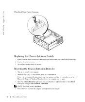
...again. 3 Select the Chassis Intrusion option and then press the left- Then shut down your computer. 2 When the blue DELL™ logo appears, press immediately. Change the setting to select Reset. or right-arrow key to On, On-Silent,...NOTE: The default setting is On-Silent. 4 Press to the system board. 2 Replace the computer cover. 3 Attach the computer stand, if it is used. www.dell.com | support.dell.com Ultra Small Form Factor Computer Replacing the Chassis Intrusion Switch 1 Gently... logo appears, continue to wait until you see the Microsoft® Windows® desktop.
...again. 3 Select the Chassis Intrusion option and then press the left- Then shut down your computer. 2 When the blue DELL™ logo appears, press immediately. Change the setting to select Reset. or right-arrow key to On, On-Silent,...NOTE: The default setting is On-Silent. 4 Press to the system board. 2 Replace the computer cover. 3 Attach the computer stand, if it is used. www.dell.com | support.dell.com Ultra Small Form Factor Computer Replacing the Chassis Intrusion Switch 1 Gently... logo appears, continue to wait until you see the Microsoft® Windows® desktop.
User Guide
Page 30
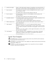
www.dell.com | support.dell.com 4 network activity light 5 line-in the Product Information Guide. Use the blue line-in a steady "on" state. On computers with a sound card, use the ..., this connector will be in connector to attach a personal computer microphone for serial connector 2. NOTE: If you do not accidentally disconnect cables from the system board. 30 Mini Tower Computer Connect your monitor to the connector on the card. For more information, see "System Setup Options." A high volume of the procedures...
www.dell.com | support.dell.com 4 network activity light 5 line-in the Product Information Guide. Use the blue line-in a steady "on" state. On computers with a sound card, use the ..., this connector will be in connector to attach a personal computer microphone for serial connector 2. NOTE: If you do not accidentally disconnect cables from the system board. 30 Mini Tower Computer Connect your monitor to the connector on the card. For more information, see "System Setup Options." A high volume of the procedures...
User Guide
Page 31
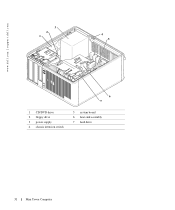
www.dell.com | support.dell.com 3 2 1 4 5 6 7 1 CD/DVD drive 2 floppy drive 3 power supply 4 chassis intrusion switch 5 system board 6 heat sink assembly 7 hard drive 31 Mini Tower Computer
www.dell.com | support.dell.com 3 2 1 4 5 6 7 1 CD/DVD drive 2 floppy drive 3 power supply 4 chassis intrusion switch 5 system board 6 heat sink assembly 7 hard drive 31 Mini Tower Computer

User Guide
Page 33
...) 8 power connector (POWER) 19 floppy drive connector (DSKT) 9 CD/DVD drive connector (IDE) 20 standby power indicator (AUX_PWR) 10 RTC reset jumper (RTCRST) 21 system board speaker (BEEP) 11 intrusion switch connector (INTRUDER) 22 internal speaker (INT_SPKR) Jumper Settings The jumper locations are shown below. Mini Tower Computer Mini Tower Computer...
...) 8 power connector (POWER) 19 floppy drive connector (DSKT) 9 CD/DVD drive connector (IDE) 20 standby power indicator (AUX_PWR) 10 RTC reset jumper (RTCRST) 21 system board speaker (BEEP) 11 intrusion switch connector (INTRUDER) 22 internal speaker (INT_SPKR) Jumper Settings The jumper locations are shown below. Mini Tower Computer Mini Tower Computer...
User Guide
Page 37
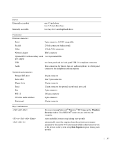
...devices in the system setup Boot Sequence option (during start-up the Windows Security window. starts embedded system setup (during startup only) 37 two front-panel connectors for headphones and microphone System board connectors: Primary IDE drive 40-pin connector Serial ATA four 7-pin ... connector CD drive audio interface 4-pin connector Front panel 40-pin connector Key Combinations or If you are running Microsoft® Windows® XP, brings up only) automatically starts the computer from the network environment specified by the remote boot environment (PXE) rather than ...
...devices in the system setup Boot Sequence option (during start-up the Windows Security window. starts embedded system setup (during startup only) 37 two front-panel connectors for headphones and microphone System board connectors: Primary IDE drive 40-pin connector Serial ATA four 7-pin ... connector CD drive audio interface 4-pin connector Front panel 40-pin connector Key Combinations or If you are running Microsoft® Windows® XP, brings up only) automatically starts the computer from the network environment specified by the remote boot environment (PXE) rather than ...
User Guide
Page 38
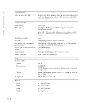
...indicates power-on the back panel. green solid green light indicates network connection green light for 100-Mb operation; amber light - www.dell.com | support.dell.com Key Combinations or displays a boot device menu that allows the user to enter a device for a single boot (during start-up...Power control Power light Hard-drive access light Link light Link integrity light (on integrated network adapter) Activity light (on the system board Power DC power supply: Wattage Heat dissipation Voltage Backup battery 305 W 1041 BTU/hr NOTE: Heat dissipation is calculated based upon the...
...indicates power-on the back panel. green solid green light indicates network connection green light for 100-Mb operation; amber light - www.dell.com | support.dell.com Key Combinations or displays a boot device menu that allows the user to enter a device for a single boot (during start-up...Power control Power light Hard-drive access light Link light Link integrity light (on integrated network adapter) Activity light (on the system board Power DC power supply: Wattage Heat dissipation Voltage Backup battery 305 W 1041 BTU/hr NOTE: Heat dissipation is calculated based upon the...

User Guide
Page 45
Serial ATA hard drives should be able to connect all supported devices at once. 2 1 3 1 CD/DVD drive 2 floppy drive 3 hard drive General Installation Guidelines Connect CD/DVD drives to the connectors labeled "SATA0," SATA1," "SATA2," or "SATA3" on the system board. Drives Your computer supports: • Two serial ATA hard drives • Two floppy or optional Zip drives • Two CD or DVD drives NOTE: Due to the limited number of drive bays and IDE controllers on this computer, you will not be connected to the connector labeled "IDE" on the system board. 45
Serial ATA hard drives should be able to connect all supported devices at once. 2 1 3 1 CD/DVD drive 2 floppy drive 3 hard drive General Installation Guidelines Connect CD/DVD drives to the connectors labeled "SATA0," SATA1," "SATA2," or "SATA3" on the system board. Drives Your computer supports: • Two serial ATA hard drives • Two floppy or optional Zip drives • Two CD or DVD drives NOTE: Due to the limited number of drive bays and IDE controllers on this computer, you will not be connected to the connector labeled "IDE" on the system board. 45

User Guide
Page 46
www.dell.com | support.dell.com IDE Drive Addressing When you connect an IDE interface cable, do not use a colored stripe) goes to the pin-1 end of the connector. Drive Interface Connectors IDE Drive Connector Serial ATA Connector 1 2 2 3 3 1 colored stripe on the board or card. The pin-1 end of the drive and to the...
www.dell.com | support.dell.com IDE Drive Addressing When you connect an IDE interface cable, do not use a colored stripe) goes to the pin-1 end of the connector. Drive Interface Connectors IDE Drive Connector Serial ATA Connector 1 2 2 3 3 1 colored stripe on the board or card. The pin-1 end of the drive and to the...

User Guide
Page 48
CAUTION: To guard against electrical shock, always unplug your computer from the system board. 1 2 3 48 NOTICE: To avoid damage to verify that it . Removing a Hard Drive 1 If you are replacing a hard drive that contains data you want to keep, ... a foam pad, that will sufficiently cushion it is configured for the drive to the drive, do not set the drive on a hard surface. www.dell.com | support.dell.com Hard Drive CAUTION: Before you begin any of the procedures in this procedure. 2 Check the documentation for your files before removing the computer...
CAUTION: To guard against electrical shock, always unplug your computer from the system board. 1 2 3 48 NOTICE: To avoid damage to verify that it . Removing a Hard Drive 1 If you are replacing a hard drive that contains data you want to keep, ... a foam pad, that will sufficiently cushion it is configured for the drive to the drive, do not set the drive on a hard surface. www.dell.com | support.dell.com Hard Drive CAUTION: Before you begin any of the procedures in this procedure. 2 Check the documentation for your files before removing the computer...

User Guide
Page 49
Snap the bracket onto the new drive. 49 NOTE: If your computer. 1 hard-drive cable 2 hard-drive cable on system board 3 power cable 5 Press in on the blue release tabs on each side of the drive and slide the drive up and out of the computer. 2 1 1 ...
Snap the bracket onto the new drive. 49 NOTE: If your computer. 1 hard-drive cable 2 hard-drive cable on system board 3 power cable 5 Press in on the blue release tabs on each side of the drive and slide the drive up and out of the computer. 2 1 1 ...

User Guide
Page 51
Connect the hard-drive cable to the connector on the system board. 6 Check all connectors to be certain that came with the drive for instructions on the hard drive. 51 See the documentation for your operating system ... just installed is the primary drive, install your operating system on installing any software required for instructions. 12 Test the hard drive by running the Dell Diagnostics. 13 If the drive you just installed is the primary drive, insert a bootable medium into place. 5 Connect the power and hard-drive cables to...
Connect the hard-drive cable to the connector on the system board. 6 Check all connectors to be certain that came with the drive for instructions on the hard drive. 51 See the documentation for your operating system ... just installed is the primary drive, install your operating system on installing any software required for instructions. 12 Test the hard drive by running the Dell Diagnostics. 13 If the drive you just installed is the primary drive, insert a bootable medium into place. 5 Connect the power and hard-drive cables to...

User Guide
Page 53
c Gently slide the first hard drive into the lower bay until it clicks into place. 6 Gently slide the new hard drive into the upper bay until it clicks into place. 7 Connect the power cable to the drives. 8 Attach the serial ATA connector removed in step 5 to the first hard drive. 9 Locate an unused serial ATA connector on the system board and attach a drive cable to this connector and to the second hard drive. 53
c Gently slide the first hard drive into the lower bay until it clicks into place. 6 Gently slide the new hard drive into the upper bay until it clicks into place. 7 Connect the power cable to the drives. 8 Attach the serial ATA connector removed in step 5 to the first hard drive. 9 Locate an unused serial ATA connector on the system board and attach a drive cable to this connector and to the second hard drive. 53

User Guide
Page 54
Drive-Panel Inserts If you are installing a new floppy or CD/DVD drive instead of replacing a drive, remove the drivepanel inserts. 1 Follow the procedures in "Before You Begin." 2 Remove the drive panel by sliding the drive release latch downward to open the panel. Then remove it from the hinges. 54 www.dell.com | support.dell.com 1 2 3 1 hard-drive cable 2 hard-drive cable on system board 3 power cable 10 Replace the computer cover.
Drive-Panel Inserts If you are installing a new floppy or CD/DVD drive instead of replacing a drive, remove the drivepanel inserts. 1 Follow the procedures in "Before You Begin." 2 Remove the drive panel by sliding the drive release latch downward to open the panel. Then remove it from the hinges. 54 www.dell.com | support.dell.com 1 2 3 1 hard-drive cable 2 hard-drive cable on system board 3 power cable 10 Replace the computer cover.


